EP1319924B2 - Höhenmessgerät - Google Patents
Höhenmessgerät Download PDFInfo
- Publication number
- EP1319924B2 EP1319924B2 EP01811216A EP01811216A EP1319924B2 EP 1319924 B2 EP1319924 B2 EP 1319924B2 EP 01811216 A EP01811216 A EP 01811216A EP 01811216 A EP01811216 A EP 01811216A EP 1319924 B2 EP1319924 B2 EP 1319924B2
- Authority
- EP
- European Patent Office
- Prior art keywords
- carriage
- friction
- measuring
- driving motor
- upper pulley
- Prior art date
- Legal status (The legal status is an assumption and is not a legal conclusion. Google has not performed a legal analysis and makes no representation as to the accuracy of the status listed.)
- Expired - Lifetime
Links
Images

Classifications
-
- G—PHYSICS
- G01—MEASURING; TESTING
- G01B—MEASURING LENGTH, THICKNESS OR SIMILAR LINEAR DIMENSIONS; MEASURING ANGLES; MEASURING AREAS; MEASURING IRREGULARITIES OF SURFACES OR CONTOURS
- G01B3/00—Measuring instruments characterised by the use of mechanical techniques
- G01B3/002—Details
- G01B3/008—Arrangements for controlling the measuring force
-
- G—PHYSICS
- G01—MEASURING; TESTING
- G01B—MEASURING LENGTH, THICKNESS OR SIMILAR LINEAR DIMENSIONS; MEASURING ANGLES; MEASURING AREAS; MEASURING IRREGULARITIES OF SURFACES OR CONTOURS
- G01B5/00—Measuring arrangements characterised by the use of mechanical techniques
- G01B5/02—Measuring arrangements characterised by the use of mechanical techniques for measuring length, width or thickness
- G01B5/06—Measuring arrangements characterised by the use of mechanical techniques for measuring length, width or thickness for measuring thickness
- G01B5/061—Measuring arrangements characterised by the use of mechanical techniques for measuring length, width or thickness for measuring thickness height gauges
Definitions
- the present invention relates to a measuring machine, in particular a measuring column of longitudinal dimension, for example a height measuring column.
- a measurement column generally comprises a fixed frame with a base, a carriage that can move vertically along the frame, a drive device of the carriage and a system for measuring the vertical position of the carriage.
- a key is linked to the carriage and intended to be brought into contact with the piece to be measured.
- Some measurement columns comprise a base provided with means for creating an air cushion to easily move the height measurement column on the work plane.
- the measurement column described in US4924598 comprises an electric motor housed in the base and driving the lower pulley through an axis or a transmission belt.
- the lower pulley drives a drive belt connected to the carriage, and a counterweight moving in the opposite direction to the carriage.
- the drive belt is stretched between the lower and upper pulleys.
- the carriage comprises bearings for pressing on guide rails connected to the frame.
- the electronic measuring system makes it possible to determine the position of the truck, and therefore of the key, and to display it on an electronic display.
- the resolution and accuracy that is expected of this type of measurement columns is of the order of one micron.
- This accuracy depends to a large extent on the contact force between the key and the workpiece.
- a large contact force causes bending of the key and / or the workpiece, or even an elastic deformation of the material, which may influence the measurement.
- the contact force between the key and the part to be measured must therefore be minimal or, in any case, identical to each measurement.
- a heavy and bulky column made up of many distinct elements, is indeed difficult to handle, expensive to produce and transport, and more exposed to failures and failures.
- the US399669 describes a measurement column in which the probing key is driven by a pair of augers.
- An object of the present invention is to provide a measurement column of longitudinal dimensions that avoids the disadvantages of columns of the prior art.
- an object of the present invention is to provide a measurement column of longitudinal dimensions in which the belt or drive cable of the carriage is less taut than in the devices of the prior art, and whose overall size is reduced.
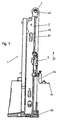
- An example of a measuring column comprises a vertical frame 2 mounted perpendicularly on a base 20.
- the frame comprises a front face provided with a not shown ruler and guide rails 24.
- the ruler is provided with capacitive electrodes or magnetic, for example, allowing an absolute or relative position measurement by means of a sensor (not shown) mounted on the carriage 3.
- the rails 24 can be mounted or preferably machined on frame 2 and constitute a flat bearing surface on which move the bearings of the carriage 3.
- Other rails on a rear face of the frame 2 form a rear rolling surface for additional bearings.
- a motorized drive mechanism connected to the frame comprises an upper pulley 42 and a lower pulley, not shown.
- the drive mechanism further comprises a motor described in connection with the figure 2 and for driving in rotation the upper pulley 42, and a cable or a belt 40 forming a loop stretched between the two pulleys.
- the carriage 3 is fixed on the first strand of the belt 40 and can thus be driven along the vertical axis z by means of the motor.
- An unillustrated counterweight fixed to the other end of the belt 40 moves in a direction opposite to the carriage 3 inside the frame 2.
- the traction force of the belt 40 is precisely controlled, for example by means of friction described below between the motor and the drive pulley, and / or by controlling the drive torque of the motor.
- a key 44 is mounted on the carriage 3 by means of a key holder 45.
- the spherical end of the key 44 is intended to be brought into contact with the workpiece to be measured.
- a measuring system of the capacitive, inductive, optoelectronic or magnetoresistive type makes it possible to indicate on a non-represented electronic display the position of the key 44 or the movement performed by the key 44 between two measurement points.
- the measuring system comprises for example an electronic sensor mounted on the carriage 3 facing the rule 22 and connected by a flexible cable mat not shown, possibly by a local radio link, to a control console and measurement display .
- the motorized driving device is illustrated in more detail on the Figures 2 and 3 . It comprises an upper pulley 42 driving the belt 40 (not shown) by friction on its outer face 423.
- the pulley 42 can be rotated in both directions and with a variable speed by means of the integrated drive motor 5.
- the electric motor 5 preferably comprises an integrated gearbox for reducing the rotational speed of the axis 51 and increasing the transmitted torque.
- a friction wheel 6 is rotated by the axis 51 engaged in the opening 63.
- the wheel 6 comprises in this example two friction pads 60 each supported by a spring or an elastic member 62 against the inner face 420 of the upper pulley 42.
- the friction surface of the friction pads 60 is preferably curved with the same diameter of curvature as the inner face 420 and has one or more grooves 61 through which any dust or tiny chips between the two friction surfaces can be evacuated.
- the driving of the pulley 42 is achieved by the friction torque between the pads 6 and the pulley 42; this torque is determined by the springs 62.
- the springs 62 are used in their linear operating zone, that is to say that the bearing pressure of the pads 60 against the surface 420 depends very little on the thickness of the pads 60.
- the body of the motor 5 is held by a spring 251 in a notch 250 provided in a fork 25 fixed to the top of the frame 2.
- a ball bearing 50 (shown without the balls) allows the pulley 42 to rotate around the body of the engine .
- the pulley 42 is held through a second bearing 421 by a second spring 253 in a second notch 252 provided in the other end of the fork 25.
- this construction is extremely compact and thus allows to save space. Furthermore, it essentially uses parts 50, 6, 60, 42, 421 turned, which are easy to machine and therefore economical.
- the drive belt 40 is stretched on the outer surface of the pulley 42 only by the weight of the carriage 3 on one of the two strands and the weight of the counterweight on the other strand. No additional tensioners are necessary (although possible), which simplifies the construction. The tension on the belt 40 can thus be reduced, which limits the stresses applied on the carriage 3 and improves the accuracy.
- the friction 6 makes it possible to control the torque transmitted by the drive motor 5 to the pulley 42, and in particular to limit the torque to a predetermined value, especially when the key 44 bears against the part to be measured.
- the pressing force of the key 44 against the measured part is thus determined by the characteristics of the friction 6, in particular by the characteristics of the springs 62.
- the friction 6 also makes it possible to protect the motor from inadvertent heating or even destruction when the carriage is suddenly moved by hand, or when the movement of the carriage is blocked.
- the drive motor 5 is controlled by a not shown control electronics for varying the motor current so as to control the rotational speed and the driving torque. It is also possible, in the context of this invention, to control the driving torque and therefore the pressing pressure of the key 44 by acting on this current. This electrical control can be performed in addition to or instead of the mechanical torque control performed using friction 6.
- the arrangement of the motorized driving device with the pulley 42, the driving motor 5 and the friction 6 at the top of the measuring column is advantageous, as we have seen, for reducing the tension required on the belt.
Landscapes
- Physics & Mathematics (AREA)
- General Physics & Mathematics (AREA)
- A Measuring Device Byusing Mechanical Method (AREA)
- Connection Of Motors, Electrical Generators, Mechanical Devices, And The Like (AREA)
Claims (8)
- Säule zur Messung von longitudinalen Dimensionen (1) mit:einem Gestell (2),einem Wagen (3), der sich entlang einer Messachse (z) entlang des Gestells bewegen kann,einem Taster (44), der mit dem besagten Wagen verbunden ist und dazu bestimmt ist, in Kontakt mit dem Messstück gebracht zu werden,einer motorisierten Antriebvorrichtung des Wagens mit einem Kabel oder Riemen (40), um den besagten Wagen entlang der besagten Messachse anzutreiben, und einem Antriebmotor (5),einem Messsystem der Position des besagten Wagens (3) entlang der besagten Messachse,worin das besagte Kabel oder der besagte Riemen (40) eine Schlaufe bildet, welche zwischen einer oberen Seilscheibe (42) auf der oberen Seite des besagten Gestells (2) und einer unteren Seilscheibe auf der unteren Seite des besagten Gestells angespannt ist, wobei der besagte Wagen (3) auf einem der beiden Enden der besagten Schlaufe montiert ist, wobei ein Gegengewicht auf dem anderen der besagten zwei Enden der besagten Schlaufe montiert ist,wobei der besagte Antriebmotor (5) auf die oberen Seite des besagten Gestells angeordnet ist und die besagte obere Seilscheibe (42) durch eine Kupplung (6) in Drehung antreibt, dadurch gekennzeichnet, dass worin der besagte Antriebmotor (5) und die besagte Kupplung (6) innerhalb der besagten oberen Seilscheibe (42) integriert sind.
- Messsäule gemäss dem vorhergehenden Anspruch, worin der besagte Antriebmotor (5) die besagte obere Seilscheibe (42) durch eine Untersetzungsgetriebe antreibt.
- Messsäule gemäss dem vorhergehenden Anspruch, worin ein Lager (50) zwischen dem Körper des besagten Antriebmotors (5) und der Innenseite (420) der besagten oberen Seilscheibe (42) vorgesehen ist.
- Messsäule gemäss einem der Ansprüche 2 oder 3, worin die besagte Friktion (6) ein durch den besagten Antriebmotor (5) angetriebenes Friktionsrad (6) umfasst, wobei das besagte Friktionsrad (6) seinerseits die besagte obere Seilscheibe (42) durch mindestens einen Friktionsgleitschuh (60) antreibt.
- Messsäule gemäss dem vorhergehenden Anspruch, worin die Friktionskraft zwischen dem besagten mindestens einem FriktionsGleitschuh (60) und der besagten oberen Seilscheibe (42) durch eine Feder (62) bestimmt wird, welche den besagten Friktionsgleitschuh (6) gegen die Innenseite (420) der besagten oberen Seilscheibe (42) drückt.
- Messsäule gemäss einem der Ansprüche 4 oder 5, worin der besagte mindestens ein Friktionsgleitschuh (6) mindestens eine Rille (61) auf seiner Friktionsfläche aufweist.
- Messsäule gemäss einem der vorhergehenden Ansprüche, worin der besagte Antriebmotor (5) durch eine Steuerelektronik gesteuert wird, welche den Strom des besagten Motors zu variieren erlaubt, um den Antriebmoment zu kontrollieren.
- Messsäule gemäss einem der Ansprüche 2 bis 7, worin der besagte Antriebmotor (5) und die besagte obere Seilscheibe (42) auf einer Gabel (25) am oberen Teil des besagten Gestells montiert sind, wobei der Körper des besagten Antriebmotors (5) durch einen der Zacken der besagten Gabel gehalten wird und die besagte obere Seilscheibe am anderen Zacken der besagten Gabel durch einen Lager (421) verbunden ist.
Priority Applications (6)
| Application Number | Priority Date | Filing Date | Title |
|---|---|---|---|
| DE60131666T DE60131666T2 (de) | 2001-12-12 | 2001-12-12 | Höhenmessgerät |
| EP01811216A EP1319924B2 (de) | 2001-12-12 | 2001-12-12 | Höhenmessgerät |
| US10/314,835 US6751884B2 (en) | 2001-12-12 | 2002-12-09 | Column for measuring longitudinal dimensions |
| JP2002356191A JP3699704B2 (ja) | 2001-12-12 | 2002-12-09 | 長さ寸法測定用コラム及び動力駆動装置 |
| CNB021561486A CN1232796C (zh) | 2001-12-12 | 2002-12-11 | 一种测量纵向尺寸的测量柱 |
| HK03106904A HK1054782A1 (en) | 2001-12-12 | 2003-09-25 | Column for measuring longitudinal dimensions |
Applications Claiming Priority (1)
| Application Number | Priority Date | Filing Date | Title |
|---|---|---|---|
| EP01811216A EP1319924B2 (de) | 2001-12-12 | 2001-12-12 | Höhenmessgerät |
Publications (3)
| Publication Number | Publication Date |
|---|---|
| EP1319924A1 EP1319924A1 (de) | 2003-06-18 |
| EP1319924B1 EP1319924B1 (de) | 2007-11-28 |
| EP1319924B2 true EP1319924B2 (de) | 2012-04-11 |
Family
ID=8184310
Family Applications (1)
| Application Number | Title | Priority Date | Filing Date |
|---|---|---|---|
| EP01811216A Expired - Lifetime EP1319924B2 (de) | 2001-12-12 | 2001-12-12 | Höhenmessgerät |
Country Status (6)
| Country | Link |
|---|---|
| US (1) | US6751884B2 (de) |
| EP (1) | EP1319924B2 (de) |
| JP (1) | JP3699704B2 (de) |
| CN (1) | CN1232796C (de) |
| DE (1) | DE60131666T2 (de) |
| HK (1) | HK1054782A1 (de) |
Families Citing this family (11)
| Publication number | Priority date | Publication date | Assignee | Title |
|---|---|---|---|---|
| EP1241436B1 (de) * | 2001-03-14 | 2014-11-19 | Tesa Sa | Koordinatenmessmaschine und Verfahren zum Einbringen eines Kommandos zum Ändern des Messmodus |
| US20060191154A1 (en) * | 2004-08-27 | 2006-08-31 | Thilo Kraemer | Method for measuring the thickness and/or length of objects and devices for this purpose |
| DE602006011792D1 (de) * | 2006-04-18 | 2010-03-04 | Hexagon Metrology Spa | Horizontalarm-koordinatenmessmaschine |
| EP1847798B1 (de) * | 2006-04-19 | 2009-10-07 | Tesa SA | Vorrichtung zur Messung von Dimensionen und vertikale Säule mit einer solchen Vorrichtung |
| TWI417515B (zh) * | 2007-08-03 | 2013-12-01 | Hon Hai Prec Ind Co Ltd | 高度儀 |
| CN102135419B (zh) * | 2010-01-23 | 2015-02-11 | 鸿富锦精密工业(深圳)有限公司 | 微动测量装置 |
| CN104105944B (zh) | 2012-03-02 | 2016-11-09 | 海克斯康测量技术有限公司 | 具有带弹簧的支撑梁的坐标测量机 |
| CN102944158B (zh) * | 2012-10-22 | 2017-02-08 | 安徽誉丰汽车技术有限责任公司 | 一种机动车发动机皮带长度检测装置 |
| DE102014101577A1 (de) * | 2014-02-07 | 2015-08-13 | Helmut Fischer GmbH Institut für Elektronik und Messtechnik | Verfahren zur elektrischen Ansteuerung eines Messstativs sowie Messstativ zur Aufnahme einer Messsonde |
| CN104074942B (zh) * | 2014-06-23 | 2016-08-24 | 苏州博众精工科技有限公司 | 一种龙门伺服同步驱动及双丝杆单驱动机构 |
| US9933248B2 (en) * | 2016-07-20 | 2018-04-03 | Tesa Sa | Height gauge |
Citations (2)
| Publication number | Priority date | Publication date | Assignee | Title |
|---|---|---|---|---|
| DE3109856A1 (de) † | 1981-03-14 | 1982-09-23 | Mauser-Werke Oberndorf Gmbh, 7238 Oberndorf | Hoehenmessgeraet |
| EP0834463A1 (de) † | 1996-10-07 | 1998-04-08 | Inventio Ag | Kompakt-Antrieb für Aufzüge |
Family Cites Families (5)
| Publication number | Priority date | Publication date | Assignee | Title |
|---|---|---|---|---|
| US3996669A (en) * | 1972-12-01 | 1976-12-14 | Finike Italiana Marposs-Soc. In Accomandita Semplice Di Mario Possati & C. | Wide-range device for measuring the linear sizes of mechanical workpieces |
| JPS58113084A (ja) * | 1981-12-28 | 1983-07-05 | 三菱電機株式会社 | 駆動装置 |
| US4679326A (en) * | 1984-11-21 | 1987-07-14 | Mitutoyo Mfg. Co., Ltd. | Height gauge |
| DE3719509A1 (de) * | 1987-06-11 | 1988-12-22 | Mauser Werke Oberndorf | Hoehenmessgeraet |
| CH687163A5 (fr) * | 1992-07-16 | 1996-09-30 | Tesa Sa | Appareil de mesure de grandeurs linéaires. |
-
2001
- 2001-12-12 DE DE60131666T patent/DE60131666T2/de not_active Expired - Lifetime
- 2001-12-12 EP EP01811216A patent/EP1319924B2/de not_active Expired - Lifetime
-
2002
- 2002-12-09 JP JP2002356191A patent/JP3699704B2/ja not_active Expired - Fee Related
- 2002-12-09 US US10/314,835 patent/US6751884B2/en not_active Expired - Lifetime
- 2002-12-11 CN CNB021561486A patent/CN1232796C/zh not_active Expired - Fee Related
-
2003
- 2003-09-25 HK HK03106904A patent/HK1054782A1/xx not_active IP Right Cessation
Patent Citations (2)
| Publication number | Priority date | Publication date | Assignee | Title |
|---|---|---|---|---|
| DE3109856A1 (de) † | 1981-03-14 | 1982-09-23 | Mauser-Werke Oberndorf Gmbh, 7238 Oberndorf | Hoehenmessgeraet |
| EP0834463A1 (de) † | 1996-10-07 | 1998-04-08 | Inventio Ag | Kompakt-Antrieb für Aufzüge |
Also Published As
| Publication number | Publication date |
|---|---|
| US20030106236A1 (en) | 2003-06-12 |
| US6751884B2 (en) | 2004-06-22 |
| CN1232796C (zh) | 2005-12-21 |
| DE60131666D1 (de) | 2008-01-10 |
| JP2003194503A (ja) | 2003-07-09 |
| HK1054782A1 (en) | 2003-12-12 |
| CN1424555A (zh) | 2003-06-18 |
| EP1319924A1 (de) | 2003-06-18 |
| DE60131666T2 (de) | 2008-12-11 |
| JP3699704B2 (ja) | 2005-09-28 |
| EP1319924B1 (de) | 2007-11-28 |
Similar Documents
| Publication | Publication Date | Title |
|---|---|---|
| EP1319924B2 (de) | Höhenmessgerät | |
| EP0143673B1 (de) | Mit mehreren Kontaktgreifflächen versehene Greifer | |
| EP0226515B1 (de) | Untersuchungstisch mit einer längsverfahrbaren Patientenlagerstatt | |
| FR2677414A1 (fr) | Moteur equipe d'un mecanisme reducteur a vis. | |
| EP0579961B1 (de) | Messapparat zur Messung linearer Grössen | |
| CH650959A5 (fr) | Machine a finir des dentures d'engrenage. | |
| EP1319921B1 (de) | Säule zur Messung einer longitudinalen Dimension | |
| EP0165129A1 (de) | Schwerkraftausgleichsvorrichtung für einen Roboterarm | |
| EP1319922B1 (de) | Säule zur Messung von longitudinalen Dimensionen | |
| FR2897916A1 (fr) | Entrainement auxiliaire de direction,dispositif de deplacement d'arbre pour cet entrainement de direction et procede de montage d'un tel entrainement | |
| FR2599489A1 (fr) | Machine de mesure des coordonnees d'une piece | |
| EP0504003B1 (de) | Zentralpunktrückstellvorrichtung | |
| EP0337864B1 (de) | Brillengestell-Träger für eine Reproduzier-Maschine | |
| EP1252969A1 (de) | Antriebsschraubenmodul mit Stossdämpfung | |
| EP0175164B1 (de) | Vorrichtung um die axiale Position eines auf einer werkzeugmaschine zu bearbeitenden Werkstückes zu messen, insbesondere auf einer Schleifmaschine für äussere zylindrische Flächen | |
| EP4151284B1 (de) | Turnsprungbrett mit einstellbarer elastizität | |
| FR3079438A1 (fr) | Dispositif a cables pour l’application d’efforts egaux en au moins deux points ecartes l’un de l’autre | |
| FR2604382A1 (fr) | Ensemble poutre-chariot comportant des moyens d'entrainement | |
| FR3130370A1 (fr) | Système d’étalonnage en angle | |
| FR2518922A1 (fr) | Table porte-piece, notamment pour une machine d'assemblage automatique | |
| EP1324437B1 (de) | Drehkontakt mit einer externen Vorrichtung zum Spannen eines Kables | |
| FR2660066A1 (fr) | Dispositif de mesure, en particulier pour la mesure du diametre interieur d'alesages. | |
| FR2597388A1 (fr) | Dispositif d'entrainement d'une tete active de bras de robot. | |
| FR2683605A1 (fr) | Dispositif d'entrainement par contact pour convertir de facon reversible un mouvement de rotation en un mouvement lineaire. | |
| BE502713A (de) |
Legal Events
| Date | Code | Title | Description |
|---|---|---|---|
| PUAI | Public reference made under article 153(3) epc to a published international application that has entered the european phase |
Free format text: ORIGINAL CODE: 0009012 |
|
| AK | Designated contracting states |
Designated state(s): AT BE CH CY DE DK ES FI FR GB GR IE IT LI LU MC NL PT SE TR |
|
| AX | Request for extension of the european patent |
Extension state: AL LT LV MK RO SI |
|
| RAP1 | Party data changed (applicant data changed or rights of an application transferred) |
Owner name: TESA SA |
|
| 17P | Request for examination filed |
Effective date: 20031108 |
|
| AKX | Designation fees paid |
Designated state(s): CH DE FR GB LI |
|
| GRAP | Despatch of communication of intention to grant a patent |
Free format text: ORIGINAL CODE: EPIDOSNIGR1 |
|
| GRAS | Grant fee paid |
Free format text: ORIGINAL CODE: EPIDOSNIGR3 |
|
| GRAA | (expected) grant |
Free format text: ORIGINAL CODE: 0009210 |
|
| AK | Designated contracting states |
Kind code of ref document: B1 Designated state(s): CH DE FR GB LI |
|
| REG | Reference to a national code |
Ref country code: CH Ref legal event code: EP |
|
| REF | Corresponds to: |
Ref document number: 60131666 Country of ref document: DE Date of ref document: 20080110 Kind code of ref document: P |
|
| REG | Reference to a national code |
Ref country code: CH Ref legal event code: NV Representative=s name: PATENTS & TECHNOLOGY SURVEYS SA |
|
| GBT | Gb: translation of ep patent filed (gb section 77(6)(a)/1977) |
Effective date: 20080131 |
|
| PLAZ | Examination of admissibility of opposition: despatch of communication + time limit |
Free format text: ORIGINAL CODE: EPIDOSNOPE2 |
|
| PLAI | Examination of admissibility of opposition: information related to despatch of communication + time limit modified |
Free format text: ORIGINAL CODE: EPIDOSCOPE2 |
|
| PLBI | Opposition filed |
Free format text: ORIGINAL CODE: 0009260 |
|
| PLBA | Examination of admissibility of opposition: reply received |
Free format text: ORIGINAL CODE: EPIDOSNOPE4 |
|
| PLAX | Notice of opposition and request to file observation + time limit sent |
Free format text: ORIGINAL CODE: EPIDOSNOBS2 |
|
| 26 | Opposition filed |
Opponent name: MAHR GMBH Effective date: 20080828 |
|
| PLBB | Reply of patent proprietor to notice(s) of opposition received |
Free format text: ORIGINAL CODE: EPIDOSNOBS3 |
|
| APAH | Appeal reference modified |
Free format text: ORIGINAL CODE: EPIDOSCREFNO |
|
| APBM | Appeal reference recorded |
Free format text: ORIGINAL CODE: EPIDOSNREFNO |
|
| APBP | Date of receipt of notice of appeal recorded |
Free format text: ORIGINAL CODE: EPIDOSNNOA2O |
|
| APCA | Receipt of observations in appeal recorded |
Free format text: ORIGINAL CODE: EPIDOSNOBA4O |
|
| REG | Reference to a national code |
Ref country code: CH Ref legal event code: PFA Owner name: TESA SA Free format text: TESA SA#RUE DU BUGNON 38#1020 RENENS (CH) -TRANSFER TO- TESA SA#RUE DU BUGNON 38#1020 RENENS (CH) |
|
| APBU | Appeal procedure closed |
Free format text: ORIGINAL CODE: EPIDOSNNOA9O |
|
| PUAH | Patent maintained in amended form |
Free format text: ORIGINAL CODE: 0009272 |
|
| STAA | Information on the status of an ep patent application or granted ep patent |
Free format text: STATUS: PATENT MAINTAINED AS AMENDED |
|
| 27A | Patent maintained in amended form |
Effective date: 20120411 |
|
| AK | Designated contracting states |
Kind code of ref document: B2 Designated state(s): CH DE FR GB LI |
|
| REG | Reference to a national code |
Ref country code: CH Ref legal event code: AEN Free format text: BREVET MAINTENU DANS UNE FORME MODIFIEE |
|
| PGFP | Annual fee paid to national office [announced via postgrant information from national office to epo] |
Ref country code: DE Payment date: 20111222 Year of fee payment: 11 |
|
| REG | Reference to a national code |
Ref country code: DE Ref legal event code: R102 Ref document number: 60131666 Country of ref document: DE Effective date: 20120411 |
|
| REG | Reference to a national code |
Ref country code: DE Ref legal event code: R135 Ref document number: 60131666 Country of ref document: DE |
|
| PG25 | Lapsed in a contracting state [announced via postgrant information from national office to epo] |
Ref country code: DE Free format text: LAPSE BECAUSE OF FAILURE TO SUBMIT A TRANSLATION OF THE DESCRIPTION OR TO PAY THE FEE WITHIN THE PRESCRIBED TIME-LIMIT Effective date: 20120712 |
|
| REG | Reference to a national code |
Ref country code: FR Ref legal event code: PLFP Year of fee payment: 15 |
|
| REG | Reference to a national code |
Ref country code: FR Ref legal event code: PLFP Year of fee payment: 16 |
|
| REG | Reference to a national code |
Ref country code: FR Ref legal event code: PLFP Year of fee payment: 17 |
|
| PGFP | Annual fee paid to national office [announced via postgrant information from national office to epo] |
Ref country code: FR Payment date: 20191219 Year of fee payment: 19 |
|
| PGFP | Annual fee paid to national office [announced via postgrant information from national office to epo] |
Ref country code: CH Payment date: 20191219 Year of fee payment: 19 |
|
| PGFP | Annual fee paid to national office [announced via postgrant information from national office to epo] |
Ref country code: GB Payment date: 20191220 Year of fee payment: 19 |
|
| REG | Reference to a national code |
Ref country code: CH Ref legal event code: PL |
|
| GBPC | Gb: european patent ceased through non-payment of renewal fee |
Effective date: 20201212 |
|
| PG25 | Lapsed in a contracting state [announced via postgrant information from national office to epo] |
Ref country code: FR Free format text: LAPSE BECAUSE OF NON-PAYMENT OF DUE FEES Effective date: 20201231 |
|
| PG25 | Lapsed in a contracting state [announced via postgrant information from national office to epo] |
Ref country code: GB Free format text: LAPSE BECAUSE OF NON-PAYMENT OF DUE FEES Effective date: 20201212 Ref country code: CH Free format text: LAPSE BECAUSE OF NON-PAYMENT OF DUE FEES Effective date: 20201231 Ref country code: LI Free format text: LAPSE BECAUSE OF NON-PAYMENT OF DUE FEES Effective date: 20201231 |