EP1319866A1 - Gear motor - Google Patents
Gear motor Download PDFInfo
- Publication number
- EP1319866A1 EP1319866A1 EP02027677A EP02027677A EP1319866A1 EP 1319866 A1 EP1319866 A1 EP 1319866A1 EP 02027677 A EP02027677 A EP 02027677A EP 02027677 A EP02027677 A EP 02027677A EP 1319866 A1 EP1319866 A1 EP 1319866A1
- Authority
- EP
- European Patent Office
- Prior art keywords
- gear
- geared motor
- motor according
- shaft
- housing
- Prior art date
- Legal status (The legal status is an assumption and is not a legal conclusion. Google has not performed a legal analysis and makes no representation as to the accuracy of the status listed.)
- Granted
Links
Images


Classifications
-
- H—ELECTRICITY
- H02—GENERATION; CONVERSION OR DISTRIBUTION OF ELECTRIC POWER
- H02K—DYNAMO-ELECTRIC MACHINES
- H02K7/00—Arrangements for handling mechanical energy structurally associated with dynamo-electric machines, e.g. structural association with mechanical driving motors or auxiliary dynamo-electric machines
- H02K7/10—Structural association with clutches, brakes, gears, pulleys or mechanical starters
- H02K7/116—Structural association with clutches, brakes, gears, pulleys or mechanical starters with gears
-
- H—ELECTRICITY
- H02—GENERATION; CONVERSION OR DISTRIBUTION OF ELECTRIC POWER
- H02K—DYNAMO-ELECTRIC MACHINES
- H02K16/00—Machines with more than one rotor or stator
-
- H—ELECTRICITY
- H02—GENERATION; CONVERSION OR DISTRIBUTION OF ELECTRIC POWER
- H02K—DYNAMO-ELECTRIC MACHINES
- H02K7/00—Arrangements for handling mechanical energy structurally associated with dynamo-electric machines, e.g. structural association with mechanical driving motors or auxiliary dynamo-electric machines
- H02K7/06—Means for converting reciprocating motion into rotary motion or vice versa
Definitions
- the invention relates to a geared motor that acts as a compact drive is particularly useful for injection molding machines and extruder gearboxes.
- a wide variety of geared motors are known, one gear use the drive torque and drive speed one Suitable to reduce or translate the drive motor. In general, it will a high reduction ratio with high transferable performance, good Efficiency and compact dimensions are required.
- the invention provides a geared motor that meets these requirements.
- the geared motor consists of several There are electric motors, each having a drive pinion, which together are arranged symmetrically to a central output gear on a Gear shaft is attached.
- This gear motor combines the Drive power of several comparatively compact electric motors that Space-saving around the common driven gear are thus arranged high drive torque can be obtained with a compact structure
- the gear shaft is designed as a hollow shaft. This makes sense because the inner end of the gear shaft between the four outer Electric motors is basically accessible. Thus, if the Gear motor used for an extruder gear, the extruder screw pushed out or pulled out through the gear shaft become. This facilitates various maintenance tasks that are now easy can be carried out without dismantling the geared motor got to. It is also possible if the geared motor drives a Injection molding machine serves, by means of the hollow shaft, the plasticizing screw in To offset rotation and to guide a spindle in the hollow shaft, which the Injection movement in the injection molding machine causes. This way a particularly compact drive.
- the drive pinion has a pinion shaft, by a conical connection with the motor shaft of the corresponding electric motor is connected. This results in an in axial direction short connection between the pinion shaft and Motor shaft, especially when the motor shaft is hollow and through it extends through a clamping screw, by means of which the pinion shaft with the Motor shaft is clamped.
- cooling channels are provided, in particular two cooling channels between two neighboring ones Electric motors.
- the cooling channels are preferably arranged in the areas which lie above and below a plane through the two longitudinal axes of two neighboring electric motors runs because there is enough in these areas There is space for the cooling ducts without the compact structure being disturbed.
- Air can either be passed through the cooling channels.
- the cooling channels preferably at their end facing the driven gear opened so that the air can escape there.
- a cooling liquid can also be passed through the cooling channels then the cooling channels at their end facing the driven gear are closed and at this end an overflow channel between adjacent cooling channels is formed so that the adjacent cooling channels in flow in opposite directions. If still on at the same time the end of the motor housing facing away from the output gear are provided, which are each by a receiving space for one Extend electric motor and one of the cooling channels between two of the Electric motors with one of the cooling channels between two other ones Connect electric motors together, the inflow and outflow for the Coolant can be placed on the same side of the housing. simultaneously the entire motor housing can be meandering from the coolant be flowed through.
- the separate gear housing is preferably designed as a block housing, so that all bearing seats can be machined in one setup. It is only a lateral opening is provided through which the driven gear into the Gear housing can be introduced.
- the gear housing the cooling channels of the Motor housing closes. This allows using the overflow channels easily accessible on one side of the motor housing perform and close them with little effort.
- a second geared motor provided, the output gear concentric with the gear shaft of is arranged first gear motor, wherein the output gear of the second Geared motor connected to a spindle by means of a spline connection is on which the gear shaft of the first gear motor is arranged, wherein a movement thread between this gear shaft and the spindle is provided.
- the Movement nut preferably mounted in the gearbox housing by means of thrust bearings.
- the drive pinion and the driven gear are preferably helically toothed. This enables a quiet, bumpless run to accommodate the Interlocking axial loads are tapered roller bearings or Angular contact ball bearings used in an X arrangement.
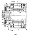
- FIG. 1 and 2 is a gear motor 5 according to a first Embodiment of the invention shown to simplify the description the term “front” refers to the left part of the geared motor in FIG. 1 5 and “rear” on the right part of the gear motor in FIG. 1.
- the geared motor has a motor housing 10 which is connected to a Gear housing 30 is screwed.
- the motor housing 10 (see also Figure 5) has a square cross section with rounded corners and takes four Electric motors 12 on There is a motor receiving space 14 for each electric motor 12 intended.
- the rotor of each electric motor 12 is open in a conventional manner a roller-mounted motor shaft 13 mounted in the motor housing 10, and the corresponding stator is fixed in the motor housing.
- the central axis of each Electric motor is designated with M.
- the electric motors are symmetrical in the Angle of 90 ° around a longitudinal axis C of the geared motor. Between a gear shaft opening 15 is provided in the motor receiving spaces 14 concentric to the longitudinal axis C from the front to the rear of the Engine case extends.
- Cooling channels 16 and 18 are in pairs on both sides of a plane through the central axes M runs between two adjacent electric motors.
- Each cooling channel has one triangular cross section, so that the space available in the housing is optimally used.
- an overflow channel 20 extending in the radial direction is provided.
- the Overflow channels 20 are closed by the gear housing 30, which on screwed on the visible front end face of the motor housing 10 becomes.
- transverse channel 22 on the rear side of the motor housing is between a radially inner cooling channel 16 between a pair of electric motors 12 to a radially outer cooling duct 18 extends between an adjacent pair of electric motors 12.
- the Cross channels 18 run approximately tangentially to the transmission shaft opening 15. Since the Cross channels 22 in the axial direction behind the cooling channels are small Bores 24 are provided, by means of which the transverse channels with the cooling channels 16, 18 connected.
- the outer ends of the transverse channels are through Screw plug 26 closed with one exception; this end serves as Output A for the coolant to be routed through the cooling channels.
- an input E is provided which serves as a bore to one of the radially outer cooling channels 18 is executed.
- the entrance E and the Output A is both at the rear end of the motor housing.
- the coolant is directed forward through the cooling channel 18, then through the overflow channel 20 radially inwards to the inside Cooling channel 16 guided and through this in the opposite direction to the rear End of the engine case. From there, the coolant is passed through the bore 24 and the transverse channel 22 to the next external cooling channel 18, in which the coolant is led back to the front of the housing, etc.
- This arrangement of cooling channels 16, 18, transverse channels 22 and Overflow channels 20, the cooling liquid is meandering through the entire Housing directed so that the motor receiving spaces 14 effective and be cooled evenly.
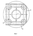
- the gear housing 30 is a block housing with a motor flange 32 which in the plane V-V of Figure 1 is screwed to the motor housing 10, and a mounting flange 34, by means of which the geared motor later For example, a machine driven by him can be screwed on. Between the motor flange 32 and the mounting flange 34 Gearbox housing a square cross section, with one side as Mounting opening 35 is open.
- the gear housing 30 receives four helical toothed pinions 36 which are integrally formed with a pinion shaft 38 by tapered roller bearings 39 is mounted in the gear housing 30.
- Each pinion shaft is a motor shaft 13 assigned to which it is connected by a cone connection as in FIG. 1 can be seen, the motor shafts 13 are hollow and have on their a conical recess at the front end while the pinion shafts attach taper at the rear end. Extends through each motor shaft 13 a turnbuckle 40 that fits into a thread in the rear end of the corresponding Pinion shaft 38 engages and pulls it into the conical recess. To this Each pinion shaft 38 is non-positively connected to the associated motor shaft 13 connected.
- gear shaft 44 is attached in a rotationally fixed manner, for example by means of a wedge connection.
- the gear shaft 44 is designed as a hollow shaft and on angular contact ball bearings 46 stored in the gear housing 30.
- the mounting opening of the gear housing 30 is through a plate 48 locked when the output gear 42 is mounted in the gear housing 30; the drive pinions 36 are mounted through the bearing openings.
- the geared motor described offers a high driving torque, because that Drive torque of the four individual electric motors is combined. At the same time, there is a very high power density, because that Total torque of the four smaller electric motors is much larger than that Torque that a single electric motor could provide in one Housing with the same dimensions can be accommodated. Finally opens up the fact that the space along the central axis of the housing does not must be installed, the possibility of a driven by the gear shaft Component through this and thus also through the motor housing withdraw. In this way, the driven component can be serviced or can be removed without having to dismantle the geared motor.
- FIGS. 6 and 7 show an assembly which consists of a first Gear motor 5 and a second gear motor 7.
- the first Gear motor corresponds to that shown in Figures 1 to 5.
- the same reference numerals for the already known components are used the same reference numerals, and it reference is made to the explanations above.
- the gear shaft 44 of the first gear motor is with tapered roller bearings stored and provided on its inner surface with a keyway profile with a spline profile that cooperates on the surface of a spindle 50 is trained.
- the spindle 50 is thus axially displaceable in the gear shaft 44 added, but can be rotated by the gear shaft.
- the second geared motor 7 has an output gear 42 ', which is on a Gear shaft 44 'is arranged, which is mounted with tapered roller bearings.
- the Gear shaft 44 ' is provided with a movement thread on the inside, into which a movement thread 52 engages on the spindle 50.
- the one consisting of the geared motor 5 and the geared motor 7 Assembly allows the spindle 50 to rotate, by means of of the gear motor 5, and to adjust in the axial direction, by means of Geared motor 7. In this way, for example, when driving a Injection molding machine being rotated using a plasticizing screw the injection movement can be effected at the same time.
- FIG. 8 shows a geared motor 5 according to a second embodiment shown.
- the same reference numerals are used, and reference is made to the above explanations directed.
- a spherical roller bearing 62 is arranged to the Spherical roller bearing 62.
- a shoulder of the gear shaft 44 In this way high axial loads can be supported.
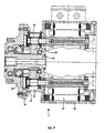
- FIGS. 9 to 11 show a gear motor according to a third Embodiment shown.
- the same reference numerals are used and it is referenced referred to the explanations above.
- the main difference from the previous embodiments is that a two-stage gearbox is used.
- the four Electric motors 12 are paired with their drive pinions 36
- Intermediate gears 64 connected, which are mounted on an intermediate shaft 66 are.
- Figures 12 and 13 is a gear motor according to a fourth Embodiment shown.
- the same reference numerals are used and it is referenced referred to the explanations above.
- the geared motor according to the fourth embodiment has two coaxial ones Output shafts or gear shafts 44, 44 'on With the gear shaft 44' one of the four electric motors 12 is coupled, while the remaining three Electric motors are coupled to the gear shaft 44.
- Main application Such a geared motor are extruders or spindle drives with two speed and gear ratio can be selected independently of each other Gear stages that enable a coaxial output of the two gear parts. For example, an inner extruder screw and an outer one Feed screw with different speeds and different Torques are driven
Abstract
Description
Die Erfindung betrifft einen Getriebemotor, der als kompakter Antrieb insbesondere für Spritzgießmaschinen und Extrudergetriebe verwendbar ist.The invention relates to a geared motor that acts as a compact drive is particularly useful for injection molding machines and extruder gearboxes.
Es sind die verschiedensten Getriebemotoren bekannt, die ein Getriebe verwenden, um das Antriebsdrehmoment und die Antriebsdrehzahl eines Antriebsmotors geeignet zu untersetzen bzw. zu übersetzen. Allgemein wird dabei ein hohes Untersetzungsverhältnis bei hoher übertragbarer Leistung, gutem Wirkungsgrad und kompakten Abmessungen gefordert.A wide variety of geared motors are known, one gear use the drive torque and drive speed one Suitable to reduce or translate the drive motor. In general, it will a high reduction ratio with high transferable performance, good Efficiency and compact dimensions are required.
Die Erfindung schafft einen Getriebemotor, der diese Anforderungen erfüllt. Erfindungsgemäß ist vorgesehen, daß der Getriebemotor aus mehreren Elektromotoren besteht, die jeweils ein Antriebsritzel aufweisen, die zusammen symmetrisch zu einem zentralen Abtriebszahnrad angeordnet sind, das auf einer Getriebewelle angebracht ist. Dieser Getriebemotor kombiniert die Antriebsleistung von mehreren vergleichsweise kompakten Elektromotoren, die platzsparend um das gemeinsame Abtriebszahnrad herum angeordnet sind Somit läßt sich bei einem kompakten Aufbau ein hohes Antriebsdrehmoment erhalten Mit dem aus den Antriebsritzeln und dem Abtriebszahnrad bestehenden Getriebe ist eine Untersetzung bis i=12 in einer einzigen Stufe erzielbar. Dies gewährleistet zum einen einen hohen Wirkungsgrad und zum anderen einen geräuscharmen Betrieb aufgrund der geringen Umfangsgeschwindigkeiten.The invention provides a geared motor that meets these requirements. According to the invention it is provided that the geared motor consists of several There are electric motors, each having a drive pinion, which together are arranged symmetrically to a central output gear on a Gear shaft is attached. This gear motor combines the Drive power of several comparatively compact electric motors that Space-saving around the common driven gear are thus arranged high drive torque can be obtained with a compact structure With the gearbox consisting of the drive pinions and the driven gear a reduction down to i = 12 can be achieved in a single step. This ensures on the one hand high efficiency and on the other hand low noise Operation due to the low peripheral speeds.
Vorzugsweise sind vier Elektromotoren vorgesehen, die im Winkel von jeweils 90° um das Abtriebszahnrad herum angeordnet sind. Auf diese Weise läßt sich ein Gehäuse mit quadratischem Querschnitt verwenden, in dessen "Ecken" jeweils ein Elektromotor angeordnet ist. Dies ergibt eine maximale Ausnutzung des Gehäusevolumens.Four electric motors are preferably provided, which are at an angle of are each arranged 90 ° around the driven gear. This way use a housing with a square cross-section, in the "corners" one electric motor each is arranged. This results in maximum utilization of the housing volume.
Gemäß einer bevorzugten Ausführungsform der Erfindung ist vorgesehen, daß die Getriebewelle als Hohlwelle ausgeführt ist. Dies ist sinnvoll, da das innenliegende Ende der Getriebewelle zwischen den vier außenliegenden Elektromotoren grundsätzlich zugänglich ist. Somit kann, wenn der Getriebemotor für ein Extrudergetriebe verwendet wird, die Extruderschnecke durch die Getriebewelle hindurch nach hinten ausgestoßen oder ausgezogen werden. Dies erleichtert verschiedene Wartungsarbeiten, die nun einfach durchgeführt werden können, ohne daß der Getriebemotor demontiert werden muß. Es ist auch möglich, wenn der Getriebemotor zum Antrieb einer Spritzgießmaschine dient, mittels der Hohlwelle die Plastifizierschnecke in Drehung zu versetzen und in der Hohlwelle eine Spindel zu führen, welche die Einspritzbewegung bei der Spritzgießmaschine bewirkt. Auf diese Weise ergibt sich ein besonders kompakter Antrieb.According to a preferred embodiment of the invention it is provided that the gear shaft is designed as a hollow shaft. This makes sense because the inner end of the gear shaft between the four outer Electric motors is basically accessible. Thus, if the Gear motor used for an extruder gear, the extruder screw pushed out or pulled out through the gear shaft become. This facilitates various maintenance tasks that are now easy can be carried out without dismantling the geared motor got to. It is also possible if the geared motor drives a Injection molding machine serves, by means of the hollow shaft, the plasticizing screw in To offset rotation and to guide a spindle in the hollow shaft, which the Injection movement in the injection molding machine causes. This way a particularly compact drive.
Vorzugsweise ist vorgesehen, daß das Antriebsritzel eine Ritzelwelle aufweist, die durch eine Konusverbindung kraftschlüssig mit der Motorwelle des entsprechenden Elektromotors verbunden ist. Auf diese Weise ergibt sich eine in axialer Richtung kurz bauende Verbindung zwischen der Ritzelwelle und der Motorwelle, insbesondere wenn die Motorwelle hohl ist und sich durch sie hindurch eine Spannschraube erstreckt, mittels der die Ritzelwelle mit der Motorwelle verspannt ist.It is preferably provided that the drive pinion has a pinion shaft, by a conical connection with the motor shaft of the corresponding electric motor is connected. This results in an in axial direction short connection between the pinion shaft and Motor shaft, especially when the motor shaft is hollow and through it extends through a clamping screw, by means of which the pinion shaft with the Motor shaft is clamped.
Zur Kühlung der Elektromotoren können im Motorgehäuse, in welchem die Elektromotoren angeordnet sind, mehrere Kühlkanäle vorgesehen sein, insbesondere jeweils zwei Kühlkanäle zwischen zwei benachbarten Elektromotoren. Die Kühlkanäle sind vorzugsweise in den Bereichen angeordnet, die oberhalb und unterhalb einer Ebene liegen, die durch die beiden Längsachsen zweier benachbarter Elektromotoren verläuft, da in diesen Bereichen genügend Platz für die Kühlkanäle ist, ohne das der kompakte Aufbau gestört wird.To cool the electric motors can in the motor housing, in which the Electric motors are arranged, several cooling channels are provided, in particular two cooling channels between two neighboring ones Electric motors. The cooling channels are preferably arranged in the areas which lie above and below a plane through the two longitudinal axes of two neighboring electric motors runs because there is enough in these areas There is space for the cooling ducts without the compact structure being disturbed.
Durch die Kühlkanäle kann entweder Luft geleitet werden. In diesem Fall sind die Kühlkanäle an ihrem dem Abtriebszahnrad zugewandten Ende vorzugsweise geöffnet, so daß die Luft dort austreten kann.Air can either be passed through the cooling channels. In this case the cooling channels preferably at their end facing the driven gear opened so that the air can escape there.
Durch die Kühlkanäle kann auch eine Kühlflüssigkeit geleitet werden, wobei dann die Kühlkanäle an ihrem dem Abtriebszahnrad zugewandten Ende verschlossen sind und wobei an diesem Ende ein Überströmkanal zwischen benachbarten Kühlkanälen gebildet ist, so daß die benachbarten Kühlkanäle in entgegengesetzten Richtungen durchströmt werden. Wenn gleichzeitig noch an dem vom Abtriebszahnrad abgewandten Ende des Motorgehäuses Querkanäle vorgesehen sind, die sich jeweils durch einen Aufnahmeraum für einen Elektromotor hindurcherstrecken und einen der Kühlkanäle zwischen zwei der Elektromotoren mit einem der Kühlkanäle zwischen zwei anderen der Elektromotoren miteinander verbinden, können der Zufluß und der Abfluß für die Kühlflüssigkeit auf derselben Seite des Gehäuses angeordnet werden. Gleichzeitig kann das gesamte Motorgehäuse mäanderförmig von der Kühlflüssigkeit durchströmt werden.A cooling liquid can also be passed through the cooling channels then the cooling channels at their end facing the driven gear are closed and at this end an overflow channel between adjacent cooling channels is formed so that the adjacent cooling channels in flow in opposite directions. If still on at the same time the end of the motor housing facing away from the output gear are provided, which are each by a receiving space for one Extend electric motor and one of the cooling channels between two of the Electric motors with one of the cooling channels between two other ones Connect electric motors together, the inflow and outflow for the Coolant can be placed on the same side of the housing. simultaneously the entire motor housing can be meandering from the coolant be flowed through.
Für das Antriebsritzel und das Abtriebszahnrad ist vorzugsweise ein separates Getriebegehäuse vorgesehen, das mit dem Motorgehäuse verschraubt ist. Das separate Getriebegehäuse ist vorzugsweise als Blockgehäuse ausgeführt, so daß sämtliche Lagersitze in einer Aufspannung bearbeitet werden können. Es ist lediglich eine seitliche Öffnung vorgesehen, durch die das Abtriebszahnrad in das Getriebegehäuse eingebracht werden kann.There is preferably a separate one for the drive pinion and the driven gear Gearbox provided, which is screwed to the motor housing. The separate gear housing is preferably designed as a block housing, so that all bearing seats can be machined in one setup. It is only a lateral opening is provided through which the driven gear into the Gear housing can be introduced.
Vorzugsweise ist vorgesehen, daß das Getriebegehäuse die Kühlkanäle des Motorgehäuses verschließt. Dies ermöglicht es, die Überströmkanäle mit geringem Aufwand an einer Seitenfläche des Motorgehäuses gut zugänglich auszuführen und sie mit geringem Aufwand zu verschließen.It is preferably provided that the gear housing the cooling channels of the Motor housing closes. This allows using the overflow channels easily accessible on one side of the motor housing perform and close them with little effort.
Gemäß einer Ausführungsform der Erfindung ist ein zweiter Getriebemotor vorgesehen, dessen Abtriebszahnrad konzentrisch mit der Getriebewelle des ersten Getriebemotors angeordnet ist, wobei das Abtriebszahnrad des zweiten Getriebemotors mittels einer Keilwellenverbindung mit einer Spindel verbunden ist, auf der die Getriebewelle des ersten Getriebemotors angeordnet ist, wobei zwischen dieser Getriebewelle und der Spindel ein Bewegungsgewinde vorgesehen ist. Auf diese Weise ergibt sich ein besonders kompakter Antrieb, der die Spindel sowohl in Drehung versetzen als auch in axialer Richtung verstellen kannAccording to one embodiment of the invention, there is a second geared motor provided, the output gear concentric with the gear shaft of is arranged first gear motor, wherein the output gear of the second Geared motor connected to a spindle by means of a spline connection is on which the gear shaft of the first gear motor is arranged, wherein a movement thread between this gear shaft and the spindle is provided. This results in a particularly compact drive that set the spindle both in rotation and in the axial direction can
Um die in Axialrichtung wirkenden Lasten aufzunehmen, ist die Bewegungsmutter vorzugsweise mittels Axiallagern im Getriebegehäuse gelagert.To absorb the loads acting in the axial direction, the Movement nut preferably mounted in the gearbox housing by means of thrust bearings.
Die Antriebsritzel und das Abtriebszahnrad sind vorzugsweise schrägverzahnt. Dies ermöglicht einen geräuscharmen, stoßfreien Lauf Zur Aufnahme der von der Verzahnung herrührenden Axiallasten werden Kegelrollenlager oder Schrägkugellager in X-Anordnung verwendet.The drive pinion and the driven gear are preferably helically toothed. This enables a quiet, bumpless run to accommodate the Interlocking axial loads are tapered roller bearings or Angular contact ball bearings used in an X arrangement.
Die Erfindung wird nachfolgend anhand verschiedener Ausführungsformen beschrieben, die in den beigefügten Zeichnungen dargestellt sind. In diesen zeigen:
- Figur 1 in einem schematischen Längsschnitt entlang der Linie I-I von
Figur 2 einen Getriebemotor mit Motorgehäuse und Getriebegehäuse gemäß einer ersten Ausführungsform der Erfindung; Figur 2 den Getriebemotor von Figur 1 in einer Draufsicht;- Figur 3 in einem Querschnitt entlang der Ebene III-III von Figur 1 das Getriebegehäuse, wobei die Antriebsritzel und das Abtriebszahnrad weggelassen wurden;
- Figur 4 das Getriebegehäuse von Figur 3 in einer Seitenansicht;
Figur 5 in einer schematischen Draufsicht auf die Ebene V-V von Figur 1 das Motorgehäuse;- Figur 6 in einer teilgeschnittenen Seitenansicht eine Baugruppe bestehend aus einem ersten Getriebemotor und einen zweiten Getriebemotor;
- Figur 7 die Baugruppe von Figur 6 in einer Vorderansicht;
- Figur 8 in einem schematischen Längsschnitt einen Getriebemotor gemäß einer zweiten Ausführungsform der Erfindung;
- Figur 9 in einer schematischen Draufsicht einen Getriebemotor gemäß einer dritten Ausführungsform der Erfindung;
Figur 10 einen Schnitt entlang der Ebene X-X von Figur 9;- Figur 11 einen Schnitt entlang der EbeneXI-XI von Figur 9;
Figur 12 eine schematische Draufsicht auf einen Getriebemotor gemäß einer vierten Ausführungsform der Erfindung;Figur 13 einen Schnitt entlang der Ebene XIII-XIII vonFigur 12.
- 1 shows a schematic longitudinal section along the line II of FIG. 2, a geared motor with a motor housing and gearbox according to a first embodiment of the invention;
- Figure 2 shows the geared motor of Figure 1 in a plan view;
- 3 shows a cross section along the plane III-III of Figure 1, the gear housing, wherein the drive pinion and the driven gear have been omitted;
- Figure 4 shows the transmission housing of Figure 3 in a side view;
- Figure 5 is a schematic plan view of the plane VV of Figure 1, the motor housing;
- Figure 6 is a partially sectioned side view of an assembly consisting of a first gear motor and a second gear motor;
- Figure 7 shows the assembly of Figure 6 in a front view;
- Figure 8 is a schematic longitudinal section of a geared motor according to a second embodiment of the invention;
- Figure 9 is a schematic plan view of a geared motor according to a third embodiment of the invention;
- Figure 10 shows a section along the plane XX of Figure 9;
- Figure 11 is a section on the plane XI-XI of Figure 9;
- Figure 12 is a schematic plan view of a geared motor according to a fourth embodiment of the invention;
- FIG. 13 shows a section along the plane XIII-XIII from FIG. 12.
In den Figuren 1 und 2 ist ein Getriebemotor 5 gemäß einer ersten
Ausführungsform der Erfindung gezeigt Zur Vereinfachung der Beschreibung
bezieht sich der Begriff "vorne" auf den in Figur 1 linken Teil des Getriebemotors
5 und "hinten" auf den in Figur 1 rechten Teil des Getriebemotors.In Figures 1 and 2 is a
Der Getriebemotor weist ein Motorgehäuse 10 auf, das mit einem
Getriebegehäuse 30 verschraubt ist. Das Motorgehäuse 10 (siehe auch Figur 5) hat
einen quadratischen Querschnitt mit abgerundeten Ecken und nimmt vier
Elektromotoren 12 auf Für jeden Elektromotor 12 ist ein Motoraufnahmeraum 14
vorgesehen. Der Rotor jedes Elektromotors 12 ist in herkömmlicher Weise auf
einer wälzgelagerten Motorwelle 13 im Motorgehäuse 10 gelagert, und der
entsprechende Stator ist fest im Motorgehäuse angebracht. Die Mittelachse jedes
Elektromotors ist mit M bezeichnet. Die Elektromotoren sind symmetrisch im
Winkel von 90° um eine Längsachse C des Getriebemotors angeordnet. Zwischen
den Motoraufnahmeräumen 14 ist eine Getriebewellenöffnung 15 vorgesehen, die
sich konzentrisch zur Längsachse C von der vorderen zur hinteren Seite des
Motorgehäuses erstreckt.The geared motor has a
Im Motorgehäuse 10 sind zwischen den einzelnen Motoraufnahmeräumen 14
jeweils zwei Kühlkanäle vorgesehen, nämlich ein radial innenliegender Kühlkanal
16 und ein radial außenliegender Kühlkanal 18. Jeweils ein Kühlkanal 16 und ein
Kühlkanal 18 liegen paarweise beiderseits einer Ebene, die durch die Mittelachsen
M zweier benachbarter Elektromotoren verläuft. Jeder Kühlkanal hat einen etwa
dreieckigen Querschnitt, so daß der im Gehäuse zur Verfügung stehende Bauraum
optimal ausgenutzt wird.In the
Zwischen jedem radial außenliegenden Kühlkanal 18 und dem benachbarten
innenliegenden Kühlkanal 16 ist an der vorderen Stirnfläche des Motorgehäuses
10 ein in radialer Richtung verlaufender Überströmkanal 20 vorgesehen. Die
Überströmkanäle 20 werden durch das Getriebegehäuse 30 verschlossen, das auf
die in Figur 5 sichtbare, vordere Stirnfläche des Motorgehäuses 10 aufgeschraubt
wird.Between each radially
Auf der hinteren Seite des Motorgehäuses ist jeweils ein Querkanal 22
vorgesehen, der sich von einem radial innenliegenden Kühlkanal 16 zwischen
einem Paar von Elektromotoren 12 zu einen radial außenliegenden Kühlkanal 18
zwischen einem benachbarten Paar von Elektromotoren 12 erstreckt. Die
Querkanäle 18 verlaufen etwa tangential zur Getriebewellenöffnung 15. Da die
Querkanäle 22 in axialer Richtung hinter den Kühlkanälen liegen, sind kleine
Bohrungen 24 vorgesehen, mittels denen die Querkanäle mit den Kühlkanälen 16,
18 verbunden. Die außenliegenden Enden der Querkanäle sind durch
Schraubstopfen 26 verschlossen bis auf eine Ausnahme; dieses Ende dient als
Ausgang A für die Kühlflüssigkeit, die durch die Kühlkanäle geleitet werden soll.
Neben dem Ausgang A ist ein Eingang E vorgesehen, der als Bohrung zur einem
der radial außenliegenden Kühlkanäle 18 ausgeführt ist. Der Eingang E und der
Ausgang A liegen beide am hinteren Ende des Motorgehäuses.There is a
Vom Eingang E wird das Kühlmittel durch den Kühlkanal 18 nach vorne,
dann durch den Überströmkanal 20 radial nach innen zum innenliegenden
Kühlkanal 16 geführt und durch diesen in Gegenrichtung wieder zum hinteren
Ende des Motorgehäuses. Vor dort wird die Kühlflüssigkeit durch die Bohrung 24
und den Querkanal 22 zum nächsten außenliegenden Kühlkanal 18 geführt, in
dem die Kühlflüssigkeit wieder zur vorderen Seite des Gehäuses geführt wird, etc.
Durch diese Anordnung von Kühlkanälen 16, 18, Querkanälen 22 und
Überströmkanälen 20 wird die Kühlflüssigkeit mäanderförmig durch das gesamte
Gehäuse geleitet, so daß die Motoraufnahmeräume 14 wirkungsvoll und
gleichmäßig gekühlt werden.From the inlet E, the coolant is directed forward through the cooling
Das Getriebegehäuse 30 ist ein Blockgehäuse mit einem Motorflansch 32, der
in der Ebene V-V von Figur 1 mit dem Motorgehäuse 10 verschraubt wird, und
einem Befestigungsflansch 34, mittels dem später der Getriebemotor an
beispielsweise eine von ihm angetriebene Maschine angeschraubt werden kann.
Zwischen dem Motorflansch 32 und dem Befestigungsflansch 34 hat das
Getriebegehäuse einen quadratischen Querschnitt, wobei eine Seite als
Montageöffnung 35 offen ausgeführt ist.The
Das Getriebegehäuse 30 nimmt vier schrägverzahnte Antriebsritzel 36 auf, die
einstückig mit einer Ritzelwelle 38 ausgebildet sind, die durch Kegelrollenlager
39 im Getriebegehäuse 30 gelagert ist. Jede Ritzelwelle ist einer Motorwelle 13
zugeordnet, mit der sie durch eine Konusverbindung verbunden ist Wie in Figur 1
zu sehen ist, sind die Motorwellen 13 hohl ausgeführt und weisen an ihrem
vorderen Ende eine konische Aussparung auf, während sich die Ritzelwellen an
ihrem hinteren Ende konisch verjüngen. Durch jede Motorwelle 13 erstreckt sich
eine Spannschraube 40, die in ein Gewinde im hinteren Ende der entsprechenden
Ritzelwelle 38 eingreift und diese in die konische Aussparung zieht. Auf diese
Weise ist jede Ritzelwelle 38 kraftschlüssig mit der zugehörigen Motorwelle 13
verbunden. The
Falls gewünscht, kann am hinteren Ende der Motorwelle auch ein
Sicherungsring angebracht werden, an dem sich die Spannschraube 40 abstützen
kann, wenn sie gelöst wird. Dies ermöglicht, die Ritzelwelle 38 aus der
Motorwelle 13 herauszudrücken.If desired, a can also be at the rear end of the motor shaft
Circlip are attached, on which the clamping
Mittig zwischen den Antriebsritzeln 36 ist ein schrägverzahntes, zur
Längsachse C konzentrisches Abtriebszahnrad 42 angeordnet. Es ist auf einer
Getriebewelle 44 drehfest angebracht, beispielsweise durch eine Keilverbindung.
Die Getriebewelle 44 ist als Hohlwelle ausgeführt und auf Schrägkugellagern 46
im Getriebegehäuse 30 gelagert.In the middle between the drive pinions 36 is a helical toothed for
Longitudinal axis C arranged
Die Montageöffnung des Getriebegehäuses 30 wird durch eine Platte 48
verschlossen, wenn das Abtriebszahnrad 42 im Getriebegehäuse 30 montiert ist;
die Antriebsritzel 36 werden durch die Lageröffnungen montiert.The mounting opening of the
Der beschriebene Getriebemotor bietet ein hohes Antriebsdrehmoment, da das Antriebsdrehmoment der vier einzelnen Elektromotoren vereinigt wird. Gleichzeitig ergibt sich eine sehr hohe Leistungsdichte, da das Gesamtdrehmoment der vier kleineren Elektromotoren sehr viel größer ist als das Drehmoment, das ein einziger Elektromotor bereitstellen könnte, der in einem Gehäuse mit denselben Abmessungen untergebracht werden kann. Schließlich eröffnet die Tatsache, daß der Raum entlang der Mittelachse des Gehäuses nicht verbaut werden muß, die Möglichkeit, ein von der Getriebewelle angetriebenes Bauteil durch diese hindurch und somit auch durch das Motorgehäuse hindurch zurückzuziehen. Auf diese Weise kann das angetriebene Bauteil gewartet oder entfernt werden, ohne daß der Getriebemotor demontiert werden muß.The geared motor described offers a high driving torque, because that Drive torque of the four individual electric motors is combined. At the same time, there is a very high power density, because that Total torque of the four smaller electric motors is much larger than that Torque that a single electric motor could provide in one Housing with the same dimensions can be accommodated. Finally opens up the fact that the space along the central axis of the housing does not must be installed, the possibility of a driven by the gear shaft Component through this and thus also through the motor housing withdraw. In this way, the driven component can be serviced or can be removed without having to dismantle the geared motor.
In den Figuren 6 und 7 ist eine Baugruppe gezeigt, die aus einem ersten
Getriebemotor 5 und einem zweiten Getriebemotor 7 besteht. Der erste
Getriebemotor entspricht demjenigen, der in den Figuren 1 bis 5 gezeigt ist. Für
die bereits bekannten Bauteile werden dieselben Bezugszeichen verwendet, und es
wird auf die obigen Erläuterungen verwiesen. FIGS. 6 and 7 show an assembly which consists of a
Die Getriebewelle 44 des ersten Getriebemotors ist mit Kegelrollenlagern
gelagert und auf ihrer Innenfläche mit einem Keilnutprofil versehen, das mit
einem Keilwellenprofil zusammenwirkt, das auf der Oberfläche einer Spindel 50
ausgebildet ist. Die Spindel 50 ist somit axial verschiebbar in der Getriebewelle
44 aufgenommen, kann jedoch von der Getriebewelle in Drehung versetzt werden.The
Der zweite Getriebemotor 7 weist ein Abtriebszahnrad 42' auf, das auf einer
Getriebewelle 44' angeordnet ist, die mit Kegelrollenlagern gelagert ist. Die
Getriebewelle 44' ist auf der Innenseite mit einem Bewegungsgewinde versehen,
in das ein Bewegungsgewinde 52 auf der Spindel 50 eingreift.The second geared motor 7 has an output gear 42 ', which is on a
Gear shaft 44 'is arranged, which is mounted with tapered roller bearings. The
Gear shaft 44 'is provided with a movement thread on the inside,
into which a
Die aus dem Getriebemotor 5 und dem Getriebemotor 7 bestehende
Baugruppe ermöglicht, die Spindel 50 in Drehung zu versetzen, und zwar mittels
des Getriebemotors 5, und in axialer Richtung zu verstellen, und zwar mittels des
Getriebemotors 7. Auf diese Weise kann beispielsweise beim Antrieb einer
Spritzgießmaschine eine Plastifizierschnecke in Drehung versetzt werden, wobei
gleichzeitig die Einspritzbewegung bewirkt werden kann.The one consisting of the geared
In Figur 8 ist ein Getriebemotor 5 gemäß einer zweiten Ausführungsform
gezeigt. Für die von der ersten Ausführungsform bekannten Bauteile werden
dieselben Bezugszeichen verwendet, und es wird auf die obigen Erläuterungen
verwiesen.8 shows a
Am Befestigungsflansch 34 des Getriebegehäuses 30 ist ein Vorspanngehäuse
60 angeschraubt, in dem ein Pendelrollenlager 62 angeordnet ist. An dem
Pendelrollenlager 62 liegt ein Absatz der Getriebewelle 44 an. Auf diese Weise
können hohe Axiallasten abgestützt werden.On the mounting
Auch bei der zweiten Ausführungsform ist es möglich, ein von der Getriebewelle angetriebenes Bauteil durch die Getriebewelle hindurch nach hinten zurückzuziehen.In the second embodiment it is also possible to use one of the Gear shaft driven component through the gear shaft to the rear withdraw.
In den Figuren 9 bis 11 ist ein Getriebemotor gemäß einer dritten Ausführungsform gezeigt. Für die von den ersten beiden Ausführungsformen bekannten Bauteile werden dieselben Bezugszeichen verwendet, und es wird auf die obigen Erläuterungen verwiesen.FIGS. 9 to 11 show a gear motor according to a third Embodiment shown. For those of the first two embodiments known components, the same reference numerals are used and it is referenced referred to the explanations above.
Der wesentlichste Unterschied zu den vorhergehenden Ausführungsformen
besteht darin, daß ein zweistufiges Getriebe verwendet wird. Die vier
Elektromotoren 12 sind paareweise über ihre Antriebsritzel 36 mit zwei
Zwischenzahnrädern 64 verbunden, die auf einer Zwischenwelle 66 angebracht
sind. Auf jeder Zwischenwelle 66 ist auch ein Zwischenritzel 68 angebracht, daß
in das mittig angeordnete Abtriebszahnrad 42 eingreift.The main difference from the previous embodiments
is that a two-stage gearbox is used. The four
Das Getriebe ermöglicht eine Untersetzung bis ca. i = 40, die sich zusammensetzt aus einer ersten Übersetzung mit i = 8 und einer zweiten Übersetzung mit i = 5. Durch die beiden Doppelzahneingriffe erhöht sich das mögliche Drehmoment gegenüber bekannten Konstruktionen um den Faktor 2. Aufgrund der Anordnung der Verzahnungen ergibt sich eine sehr kompakte Bauart mit dem Vorteil, daß der Abtrieb in gleicher Weise wie bei den vorhergehenden Ausführungsformen als Hohlwelle ausgebildet werden kann und somit für Extruder oder sonstige Anwendungen einen freien Durchtrieb nach vorne und nach hinten ermöglicht.The gearbox allows a reduction up to approx. I = 40, which is consists of a first translation with i = 8 and a second Ratio with i = 5. This increases due to the two double tooth interventions possible torque compared to known designs by a factor of 2. Due to the arrangement of the gears, a very compact result Design with the advantage that the output in the same way as in the previous embodiments can be designed as a hollow shaft and thus a free through drive for extruders or other applications allows front and back.
In den Figuren 12 und 13 ist ein Getriebemotor gemäß einer vierten Ausführungsform gezeigt. Für die von den vorangegangenen Ausführungsformen bekannten Bauteile werden die selben Bezugszeichen verwendet, und es wird auf die obigen Erläuterungen verwiesen.In Figures 12 and 13 is a gear motor according to a fourth Embodiment shown. For those of the previous embodiments known components, the same reference numerals are used and it is referenced referred to the explanations above.
Der Getriebemotor gemäß der vierten Ausrührungsform weist zwei koaxiale
Abtriebswellen oder Getriebewellen 44, 44' auf Mit der Getriebewelle 44' ist
einer der vier Elektromotoren 12 gekoppelt, während die restlichen drei
Elektromotoren mit der Getriebewelle 44 gekoppelt sind. Hauptanwendungsgebiet
eines solchen Getriebemotors sind Extruder oder Spindelantriebe mit zwei
unabhängig voneinander in der Drehzahl und der Untersetzung wählbaren
Getriebestufen, die einen koaxialen Abtrieb der beiden Getriebeteile ermöglicht.
Beispielsweise können eine innere Extruderschnecke und eine äußere
Zuführschnecke mit unterschiedlichen Drehzahlen und unterschiedlichen
Drehmomenten angetrieben werdenThe geared motor according to the fourth embodiment has two coaxial ones
Output shafts or
Es besteht die Möglichkeit, die beiden Abtriebe jeweils nach der gleichen Seite herauszuführen oder einen Abtrieb in Richtung Motorseite herauszuführen. It is possible to use the two drives each after the same Side or take an output towards the motor side.
- 5:5:
- Getriebemotorgearmotor
- 7:7:
- Getriebemotorgearmotor
- 10:10:
- Motorgehäusemotor housing
- 12:12:
- Elektromotorelectric motor
- 13:13:
- Motorwellemotor shaft
- 14:14:
- MotoraufnahmeraumMotor housing space
- 15:15:
- GetriebewellenöffnungGear shaft opening
- 16:16:
- innenliegender Kühlkanalinternal cooling duct
- 18:18:
- außenliegender Kühlkanalexternal cooling duct
- 20:20:
- Überströmkanaloverflow
- 22:22:
- QuerkanalQuerkanal
- 24:24:
- Bohrungdrilling
- 26:26:
- Schraubstopfenscrew plug
- 30:30:
- Getriebegehäusegearbox
- 32:32:
- Motorflanschmotor flange
- 34:34:
- Befestigungsflanschmounting flange
- 35:35:
- Montageöffnungmounting hole
- 36:36:
- Antriebsritzelpinion
- 38:38:
- Ritzelwellepinion shaft
- 39:39:
- KegelrollenlagerTapered roller bearings
- 40:40:
- Spannschraubeclamping screw
- 42:42:
- Abtriebszahnradoutput gear
- 44:44:
- Getriebewellegear shaft
- 46:46:
- SchrägkugellagerAngular contact ball bearings
- 48:48:
- Platteplate
- 50:50:
- Spindelspindle
- 52:52:
- Bewegungsgewindemotion thread
- 60:60:
- Vorspanngehäusebiasing housing
- 62:62:
- PendelrollenlagerSpherical roller bearings
- 64:64:
- Zwischenzahnradintermediate gear
- 66:66:
- Zwischenwelleintermediate shaft
- 68:68:
- Zwischenritzelintermediate pinion
Claims (21)
Applications Claiming Priority (4)
| Application Number | Priority Date | Filing Date | Title |
|---|---|---|---|
| DE20120218 | 2001-12-13 | ||
| DE20120218U | 2001-12-13 | ||
| DE20206979U DE20206979U1 (en) | 2001-12-13 | 2002-05-02 | gearmotor |
| DE20206979U | 2002-05-02 |
Publications (2)
| Publication Number | Publication Date |
|---|---|
| EP1319866A1 true EP1319866A1 (en) | 2003-06-18 |
| EP1319866B1 EP1319866B1 (en) | 2005-03-30 |
Family
ID=26057315
Family Applications (1)
| Application Number | Title | Priority Date | Filing Date |
|---|---|---|---|
| EP02027677A Revoked EP1319866B1 (en) | 2001-12-13 | 2002-12-12 | Gear motor |
Country Status (3)
| Country | Link |
|---|---|
| EP (1) | EP1319866B1 (en) |
| AT (1) | ATE292257T1 (en) |
| ES (1) | ES2239198T3 (en) |
Cited By (7)
| Publication number | Priority date | Publication date | Assignee | Title |
|---|---|---|---|---|
| EP1722461A1 (en) * | 2005-05-13 | 2006-11-15 | Demag Ergotech GmbH | Electric drive |
| WO2012076141A3 (en) * | 2010-12-09 | 2012-10-18 | Sew-Eurodrive Gmbh & Co. Kg | Geared motor |
| WO2012076142A3 (en) * | 2010-12-09 | 2012-11-08 | Sew-Eurodrive Gmbh & Co. Kg | Cooling arrangement and geared motor |
| DE102014207887A1 (en) * | 2014-04-28 | 2015-10-29 | Bayerische Motoren Werke Aktiengesellschaft | Electric drive unit for a vehicle |
| CN107666206A (en) * | 2016-07-28 | 2018-02-06 | 辰阔机电科技(上海)有限公司 | A kind of multi input motor combination gear-box |
| WO2020148370A1 (en) | 2019-01-18 | 2020-07-23 | Ge Energy Power Conversion Technology Limited | Mechanical drive system and associated motor compressor |
| DE102020118257A1 (en) | 2020-07-10 | 2022-01-13 | Renk Gmbh | Drive system with at least one drive unit, in particular for high-speed applications and method for operating a drive system |
Citations (6)
| Publication number | Priority date | Publication date | Assignee | Title |
|---|---|---|---|---|
| US2076015A (en) * | 1935-04-26 | 1937-04-06 | Clifford E Broome | Speed reduction power unit |
| US2173339A (en) * | 1935-01-07 | 1939-09-19 | Us Electrical Motors Inc | Geared power unit |
| US2436930A (en) * | 1944-01-17 | 1948-03-02 | Foote Bros Gear And Machine Co | Motor reducer unit |
| FR1254056A (en) * | 1960-03-11 | 1961-02-17 | Speed reducer | |
| JPS59172948A (en) * | 1983-03-22 | 1984-09-29 | Shibaura Eng Works Co Ltd | Composite brushless servo motor |
| US5463914A (en) * | 1994-02-02 | 1995-11-07 | Tyan; Li Yng | Multi-function energy saving power transmission mechanism |
-
2002
- 2002-12-12 ES ES02027677T patent/ES2239198T3/en not_active Expired - Lifetime
- 2002-12-12 AT AT02027677T patent/ATE292257T1/en not_active IP Right Cessation
- 2002-12-12 EP EP02027677A patent/EP1319866B1/en not_active Revoked
Patent Citations (6)
| Publication number | Priority date | Publication date | Assignee | Title |
|---|---|---|---|---|
| US2173339A (en) * | 1935-01-07 | 1939-09-19 | Us Electrical Motors Inc | Geared power unit |
| US2076015A (en) * | 1935-04-26 | 1937-04-06 | Clifford E Broome | Speed reduction power unit |
| US2436930A (en) * | 1944-01-17 | 1948-03-02 | Foote Bros Gear And Machine Co | Motor reducer unit |
| FR1254056A (en) * | 1960-03-11 | 1961-02-17 | Speed reducer | |
| JPS59172948A (en) * | 1983-03-22 | 1984-09-29 | Shibaura Eng Works Co Ltd | Composite brushless servo motor |
| US5463914A (en) * | 1994-02-02 | 1995-11-07 | Tyan; Li Yng | Multi-function energy saving power transmission mechanism |
Non-Patent Citations (1)
| Title |
|---|
| PATENT ABSTRACTS OF JAPAN vol. 009, no. 027 (E - 294) 6 February 1985 (1985-02-06) * |
Cited By (12)
| Publication number | Priority date | Publication date | Assignee | Title |
|---|---|---|---|---|
| EP1722461A1 (en) * | 2005-05-13 | 2006-11-15 | Demag Ergotech GmbH | Electric drive |
| WO2012076141A3 (en) * | 2010-12-09 | 2012-10-18 | Sew-Eurodrive Gmbh & Co. Kg | Geared motor |
| WO2012076142A3 (en) * | 2010-12-09 | 2012-11-08 | Sew-Eurodrive Gmbh & Co. Kg | Cooling arrangement and geared motor |
| CN103262397A (en) * | 2010-12-09 | 2013-08-21 | 索尤若驱动有限及两合公司 | Geared motor |
| US9257884B2 (en) | 2010-12-09 | 2016-02-09 | Sew-Eurodrive Gmbh & Co. Kg | Cooling system and geared motor |
| CN103262397B (en) * | 2010-12-09 | 2016-05-04 | 索尤若驱动有限及两合公司 | Reducing motor |
| DE102014207887A1 (en) * | 2014-04-28 | 2015-10-29 | Bayerische Motoren Werke Aktiengesellschaft | Electric drive unit for a vehicle |
| US10773600B2 (en) | 2014-04-28 | 2020-09-15 | Bayerische Motoren Werker Aktiengesellschaft | Electrical drive unit for a vehicle |
| CN107666206A (en) * | 2016-07-28 | 2018-02-06 | 辰阔机电科技(上海)有限公司 | A kind of multi input motor combination gear-box |
| WO2020148370A1 (en) | 2019-01-18 | 2020-07-23 | Ge Energy Power Conversion Technology Limited | Mechanical drive system and associated motor compressor |
| FR3091916A1 (en) | 2019-01-18 | 2020-07-24 | Ge Energy Power Conversion Technology Limited | Mechanical drive system and associated motor-compressor |
| DE102020118257A1 (en) | 2020-07-10 | 2022-01-13 | Renk Gmbh | Drive system with at least one drive unit, in particular for high-speed applications and method for operating a drive system |
Also Published As
| Publication number | Publication date |
|---|---|
| EP1319866B1 (en) | 2005-03-30 |
| ES2239198T3 (en) | 2005-09-16 |
| ATE292257T1 (en) | 2005-04-15 |
Similar Documents
| Publication | Publication Date | Title |
|---|---|---|
| DE10022715B4 (en) | Ball screw | |
| DE60007190T2 (en) | Electrically powered steering device | |
| EP0275485B1 (en) | Twin worm extruder | |
| DE10297160T5 (en) | Ball screw | |
| DE19931818A1 (en) | Multi-stage spur gear | |
| DE4330170A1 (en) | Six-speed double-clutch transmission | |
| DE2528173A1 (en) | DEVICE FOR TRANSMISSION OF A DRIVE FORCE | |
| DE4101132C2 (en) | Multi-function ball screw groove spindle device | |
| EP1182027A1 (en) | Drive for extrusion apparatus | |
| DE2412876C3 (en) | Plastic extrusion press with at least two screws | |
| EP1319866B1 (en) | Gear motor | |
| EP0432349B1 (en) | Transmission | |
| DE102004058551A1 (en) | Gear has device with cylindrical body extending in axial direction of wheel and pivoted in organ | |
| DE10144803B4 (en) | planetary gear | |
| EP3460293A1 (en) | Drive assembly, comprising a high speed electric motor and a toothed gearing | |
| EP0529379A1 (en) | Rotor assembly for turbomachines | |
| DE102020117269B3 (en) | Gear arrangement | |
| EP0267572A2 (en) | Headstock for lathe | |
| DD200364A1 (en) | SCHAELMASCHINE | |
| DE102015201450A1 (en) | Mechanical transmission of a machine tool | |
| DE3600494C2 (en) | ||
| DE102019120785A1 (en) | Electric drive unit, hybrid module and drive arrangement for a motor vehicle | |
| EP0860269B1 (en) | Twin screw extruder | |
| DE3431547C2 (en) | Split gear for twin screw machines | |
| DE2354440B2 (en) | Threshing drum drive for combine harvesters |
Legal Events
| Date | Code | Title | Description |
|---|---|---|---|
| PUAI | Public reference made under article 153(3) epc to a published international application that has entered the european phase |
Free format text: ORIGINAL CODE: 0009012 |
|
| AK | Designated contracting states |
Designated state(s): AT BE BG CH CY CZ DE DK EE ES FI FR GB GR IE IT LI LU MC NL PT SE SI SK TR |
|
| AX | Request for extension of the european patent |
Extension state: AL LT LV MK RO |
|
| 17P | Request for examination filed |
Effective date: 20031208 |
|
| 17Q | First examination report despatched |
Effective date: 20040119 |
|
| AKX | Designation fees paid |
Designated state(s): AT BE BG CH CY CZ DE DK EE ES FI FR GB GR IE IT LI LU MC NL PT SE SI SK TR |
|
| GRAP | Despatch of communication of intention to grant a patent |
Free format text: ORIGINAL CODE: EPIDOSNIGR1 |
|
| GRAS | Grant fee paid |
Free format text: ORIGINAL CODE: EPIDOSNIGR3 |
|
| GRAA | (expected) grant |
Free format text: ORIGINAL CODE: 0009210 |
|
| AK | Designated contracting states |
Kind code of ref document: B1 Designated state(s): AT BE BG CH CY CZ DE DK EE ES FI FR GB GR IE IT LI LU MC NL PT SE SI SK TR |
|
| PG25 | Lapsed in a contracting state [announced via postgrant information from national office to epo] |
Ref country code: SI Free format text: LAPSE BECAUSE OF FAILURE TO SUBMIT A TRANSLATION OF THE DESCRIPTION OR TO PAY THE FEE WITHIN THE PRESCRIBED TIME-LIMIT Effective date: 20050330 Ref country code: TR Free format text: LAPSE BECAUSE OF FAILURE TO SUBMIT A TRANSLATION OF THE DESCRIPTION OR TO PAY THE FEE WITHIN THE PRESCRIBED TIME-LIMIT Effective date: 20050330 Ref country code: SK Free format text: LAPSE BECAUSE OF FAILURE TO SUBMIT A TRANSLATION OF THE DESCRIPTION OR TO PAY THE FEE WITHIN THE PRESCRIBED TIME-LIMIT Effective date: 20050330 Ref country code: IE Free format text: LAPSE BECAUSE OF FAILURE TO SUBMIT A TRANSLATION OF THE DESCRIPTION OR TO PAY THE FEE WITHIN THE PRESCRIBED TIME-LIMIT Effective date: 20050330 Ref country code: CZ Free format text: LAPSE BECAUSE OF FAILURE TO SUBMIT A TRANSLATION OF THE DESCRIPTION OR TO PAY THE FEE WITHIN THE PRESCRIBED TIME-LIMIT Effective date: 20050330 Ref country code: EE Free format text: LAPSE BECAUSE OF FAILURE TO SUBMIT A TRANSLATION OF THE DESCRIPTION OR TO PAY THE FEE WITHIN THE PRESCRIBED TIME-LIMIT Effective date: 20050330 Ref country code: GB Free format text: LAPSE BECAUSE OF FAILURE TO SUBMIT A TRANSLATION OF THE DESCRIPTION OR TO PAY THE FEE WITHIN THE PRESCRIBED TIME-LIMIT Effective date: 20050330 Ref country code: FI Free format text: LAPSE BECAUSE OF FAILURE TO SUBMIT A TRANSLATION OF THE DESCRIPTION OR TO PAY THE FEE WITHIN THE PRESCRIBED TIME-LIMIT Effective date: 20050330 |
|
| REG | Reference to a national code |
Ref country code: GB Ref legal event code: FG4D Free format text: NOT ENGLISH |
|
| REG | Reference to a national code |
Ref country code: CH Ref legal event code: EP |
|
| REG | Reference to a national code |
Ref country code: CH Ref legal event code: NV Representative=s name: BUGNION S.A. |
|
| REF | Corresponds to: |
Ref document number: 50202618 Country of ref document: DE Date of ref document: 20050504 Kind code of ref document: P |
|
| REG | Reference to a national code |
Ref country code: IE Ref legal event code: FG4D Free format text: LANGUAGE OF EP DOCUMENT: GERMAN |
|
| PG25 | Lapsed in a contracting state [announced via postgrant information from national office to epo] |
Ref country code: BG Free format text: LAPSE BECAUSE OF FAILURE TO SUBMIT A TRANSLATION OF THE DESCRIPTION OR TO PAY THE FEE WITHIN THE PRESCRIBED TIME-LIMIT Effective date: 20050630 Ref country code: GR Free format text: LAPSE BECAUSE OF FAILURE TO SUBMIT A TRANSLATION OF THE DESCRIPTION OR TO PAY THE FEE WITHIN THE PRESCRIBED TIME-LIMIT Effective date: 20050630 Ref country code: DK Free format text: LAPSE BECAUSE OF FAILURE TO SUBMIT A TRANSLATION OF THE DESCRIPTION OR TO PAY THE FEE WITHIN THE PRESCRIBED TIME-LIMIT Effective date: 20050630 |
|
| PG25 | Lapsed in a contracting state [announced via postgrant information from national office to epo] |
Ref country code: PT Free format text: LAPSE BECAUSE OF FAILURE TO SUBMIT A TRANSLATION OF THE DESCRIPTION OR TO PAY THE FEE WITHIN THE PRESCRIBED TIME-LIMIT Effective date: 20050908 |
|
| REG | Reference to a national code |
Ref country code: ES Ref legal event code: FG2A Ref document number: 2239198 Country of ref document: ES Kind code of ref document: T3 |
|
| GBV | Gb: ep patent (uk) treated as always having been void in accordance with gb section 77(7)/1977 [no translation filed] |
Effective date: 20050330 |
|
| REG | Reference to a national code |
Ref country code: IE Ref legal event code: FD4D |
|
| PG25 | Lapsed in a contracting state [announced via postgrant information from national office to epo] |
Ref country code: CY Free format text: LAPSE BECAUSE OF FAILURE TO SUBMIT A TRANSLATION OF THE DESCRIPTION OR TO PAY THE FEE WITHIN THE PRESCRIBED TIME-LIMIT Effective date: 20051212 |
|
| PG25 | Lapsed in a contracting state [announced via postgrant information from national office to epo] |
Ref country code: LU Free format text: LAPSE BECAUSE OF NON-PAYMENT OF DUE FEES Effective date: 20051231 Ref country code: BE Free format text: LAPSE BECAUSE OF NON-PAYMENT OF DUE FEES Effective date: 20051231 Ref country code: MC Free format text: LAPSE BECAUSE OF NON-PAYMENT OF DUE FEES Effective date: 20051231 |
|
| PLBI | Opposition filed |
Free format text: ORIGINAL CODE: 0009260 |
|
| PLAX | Notice of opposition and request to file observation + time limit sent |
Free format text: ORIGINAL CODE: EPIDOSNOBS2 |
|
| 26 | Opposition filed |
Opponent name: BAUMUELLER ANLAGEN-SYSTEMTECHNIK GMBH & CO. Effective date: 20051229 |
|
| NLR1 | Nl: opposition has been filed with the epo |
Opponent name: BAUMUELLER ANLAGEN-SYSTEMTECHNIK GMBH & CO. |
|
| EN | Fr: translation not filed | ||
| PLAF | Information modified related to communication of a notice of opposition and request to file observations + time limit |
Free format text: ORIGINAL CODE: EPIDOSCOBS2 |
|
| PLBB | Reply of patent proprietor to notice(s) of opposition received |
Free format text: ORIGINAL CODE: EPIDOSNOBS3 |
|
| BERE | Be: lapsed |
Owner name: K & A KNODLER G.M.B.H. Effective date: 20051231 |
|
| PG25 | Lapsed in a contracting state [announced via postgrant information from national office to epo] |
Ref country code: SE Free format text: LAPSE BECAUSE OF FAILURE TO SUBMIT A TRANSLATION OF THE DESCRIPTION OR TO PAY THE FEE WITHIN THE PRESCRIBED TIME-LIMIT Effective date: 20050630 |
|
| PLAB | Opposition data, opponent's data or that of the opponent's representative modified |
Free format text: ORIGINAL CODE: 0009299OPPO |
|
| PG25 | Lapsed in a contracting state [announced via postgrant information from national office to epo] |
Ref country code: FR Free format text: LAPSE BECAUSE OF NON-PAYMENT OF DUE FEES Effective date: 20051231 |
|
| PG25 | Lapsed in a contracting state [announced via postgrant information from national office to epo] |
Ref country code: FR Free format text: LAPSE BECAUSE OF NON-PAYMENT OF DUE FEES Effective date: 20050330 |
|
| PGFP | Annual fee paid to national office [announced via postgrant information from national office to epo] |
Ref country code: ES Payment date: 20090525 Year of fee payment: 7 Ref country code: NL Payment date: 20090616 Year of fee payment: 7 |
|
| PGFP | Annual fee paid to national office [announced via postgrant information from national office to epo] |
Ref country code: AT Payment date: 20090615 Year of fee payment: 7 Ref country code: DE Payment date: 20090528 Year of fee payment: 7 Ref country code: IT Payment date: 20090529 Year of fee payment: 7 |
|
| PGFP | Annual fee paid to national office [announced via postgrant information from national office to epo] |
Ref country code: CH Payment date: 20090617 Year of fee payment: 7 |
|
| RDAF | Communication despatched that patent is revoked |
Free format text: ORIGINAL CODE: EPIDOSNREV1 |
|
| RDAG | Patent revoked |
Free format text: ORIGINAL CODE: 0009271 |
|
| STAA | Information on the status of an ep patent application or granted ep patent |
Free format text: STATUS: PATENT REVOKED |
|
| REG | Reference to a national code |
Ref country code: CH Ref legal event code: PL |
|
| 27W | Patent revoked |
Effective date: 20100207 |
|
| PG25 | Lapsed in a contracting state [announced via postgrant information from national office to epo] |
Ref country code: LI Free format text: LAPSE BECAUSE OF THE APPLICANT RENOUNCES Effective date: 20050330 Ref country code: CH Free format text: LAPSE BECAUSE OF THE APPLICANT RENOUNCES Effective date: 20050330 |
|
| PG25 | Lapsed in a contracting state [announced via postgrant information from national office to epo] |
Ref country code: IT Free format text: LAPSE BECAUSE OF NON-PAYMENT OF DUE FEES Effective date: 20091212 |
|
| PG25 | Lapsed in a contracting state [announced via postgrant information from national office to epo] |
Ref country code: ES Free format text: LAPSE BECAUSE OF NON-PAYMENT OF DUE FEES Effective date: 20091213 |