EP1319861A2 - Lageraufnahme - Google Patents
Lageraufnahme Download PDFInfo
- Publication number
- EP1319861A2 EP1319861A2 EP02027106A EP02027106A EP1319861A2 EP 1319861 A2 EP1319861 A2 EP 1319861A2 EP 02027106 A EP02027106 A EP 02027106A EP 02027106 A EP02027106 A EP 02027106A EP 1319861 A2 EP1319861 A2 EP 1319861A2
- Authority
- EP
- European Patent Office
- Prior art keywords
- bearing
- sleeve
- recesses
- outer sleeve
- holes
- Prior art date
- Legal status (The legal status is an assumption and is not a legal conclusion. Google has not performed a legal analysis and makes no representation as to the accuracy of the status listed.)
- Granted
Links
Images

Classifications
-
- F—MECHANICAL ENGINEERING; LIGHTING; HEATING; WEAPONS; BLASTING
- F16—ENGINEERING ELEMENTS AND UNITS; GENERAL MEASURES FOR PRODUCING AND MAINTAINING EFFECTIVE FUNCTIONING OF MACHINES OR INSTALLATIONS; THERMAL INSULATION IN GENERAL
- F16F—SPRINGS; SHOCK-ABSORBERS; MEANS FOR DAMPING VIBRATION
- F16F1/00—Springs
- F16F1/36—Springs made of rubber or other material having high internal friction, e.g. thermoplastic elastomers
- F16F1/38—Springs made of rubber or other material having high internal friction, e.g. thermoplastic elastomers with a sleeve of elastic material between a rigid outer sleeve and a rigid inner sleeve or pin, i.e. bushing-type
- F16F1/3863—Springs made of rubber or other material having high internal friction, e.g. thermoplastic elastomers with a sleeve of elastic material between a rigid outer sleeve and a rigid inner sleeve or pin, i.e. bushing-type characterised by the rigid sleeves or pin, e.g. of non-circular cross-section
-
- F—MECHANICAL ENGINEERING; LIGHTING; HEATING; WEAPONS; BLASTING
- F16—ENGINEERING ELEMENTS AND UNITS; GENERAL MEASURES FOR PRODUCING AND MAINTAINING EFFECTIVE FUNCTIONING OF MACHINES OR INSTALLATIONS; THERMAL INSULATION IN GENERAL
- F16F—SPRINGS; SHOCK-ABSORBERS; MEANS FOR DAMPING VIBRATION
- F16F1/00—Springs
- F16F1/36—Springs made of rubber or other material having high internal friction, e.g. thermoplastic elastomers
- F16F1/38—Springs made of rubber or other material having high internal friction, e.g. thermoplastic elastomers with a sleeve of elastic material between a rigid outer sleeve and a rigid inner sleeve or pin, i.e. bushing-type
- F16F1/3842—Method of assembly, production or treatment; Mounting thereof
Definitions
- the invention relates to a bearing receptacle for a rubber-metal bearings after the Preamble of claim 1.
- the object of the invention is to provide an easily manufactured bearing seat for a rubber-metal bearing, in particular to provide in a transmission cross member, which is the rubber-metal bearing Permanently picks up and a lot in a row by Counteracts material settling phenomena and high temperatures.
- the advantages achieved by the invention are that the rubber-metal bearing held in the bearing seat of the wearer with a tight fit in the essentially from a bearing sleeve used in the bearing seat and one with this under Form fit held outer sleeve of the bearing cooperates.
- the rubber metal bearing has a rubber body adherent to the outer sleeve made of an elastic material and this is in the provided with sharp-edged stationary metallic Storage sleeve arranged. The outer sleeve is clamped in the recesses of Bearing sleeve provided.
- the recesses consist of holes of approximately the same diameter, which are spaced apart and four holes each the corners of a square form and which are approximately evenly distributed over the peripheral surface of the bearing sleeve, where there may be more holes between these four holes.
- the recesses may also have a different geometric shape, such as polygonal or be formed rectangular, square or octagonal.
- the recesses are so in the bearing sleeve arranged that between the bearing sleeve and the outer sleeve a Positive locking in the longitudinal and transverse direction of the bearing can be achieved.
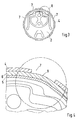
- a bearing holder 1 for a rubber metal bearing 2, for example in one Transmission carrier 3, essentially comprises a used in the bearing holder 1 Bearing sleeve 4, in which the bearing 2 is held, which on the rubber body a elastic outer sleeve 6 has.
- the bearing sleeve 4 is firmly welded in the carrier. 3 held and provided with a plurality of recesses 7.
- the bearing sleeve 4 is preferably made of metal and the introduced recesses 7 are sharp edged.
- the outer sleeve 6 of the bearing 2 consists of a Plastic or other equivalent material and is adherent to the Rubber body 5 is connected, preferably, the outer sleeve 6 on the rubber body fifth vulcanized.
- the outer sleeve 6 has a dimensional overlap relative to the bearing sleeve 4, the means that the outer diameter D of the outer sleeve 6 is greater than the inner diameter d the bearing sleeve 4, this measure is for example 2 mm.
- the recesses 7 consist in the embodiment shown from holes, each four holes form the corners of a square. There are several Holes of this arrangement distributed over the peripheral surface of the bearing sleeve 4 arranged. Between these holes further holes may be provided. It Other geometric shapes of the recesses 7 are possible.
Landscapes
- Engineering & Computer Science (AREA)
- General Engineering & Computer Science (AREA)
- Mechanical Engineering (AREA)
- Manufacturing & Machinery (AREA)
- Support Of The Bearing (AREA)
- Vibration Prevention Devices (AREA)
- Laminated Bodies (AREA)
- Sliding-Contact Bearings (AREA)
- Mounting Of Bearings Or Others (AREA)
Abstract
Description
Es zeigen
- Fig. 1
- eine schaubildliche Darstellung der mit Aussparungen versehenen Lagerhülse sowie ein einsetzbares Gummi- Metallager,
- Fig. 2
- eine schaubildliche Darstellung der fest im Träger eingesetzten Lagerhülse,
- Fig. 3
- einen vergrößerten Vertikalschnitt durch das in die Lagerhülse eingesetzte Gummi- Metallager und
- Fig. 4
- eine vergrößerte Darstellung im Bereich der Aussparungen.
Claims (5)
- Lageraufnahme für ein Gummi-Metallager in einem Getriebeträger (3), welcher in einem Lagersitz eine eingesetzte Lagerhülse (4) aufweist, dadurch gekennzeichnet, daß das Gummi-Metallager (2) eine an einem Gummikörper (5) festhaftende Außenhülse (6) aus einem elastischen Material aufweist und diese in der mit scharfkantigen Aussparungen (7) versehenen ortsfesten metallischen Lagerhülse (4) angeordnet ist wobei die elastische Außenhülse (6) eingekrallt in den Aussparungen (7) der Lagerhülse (4) gehalten wird.
- Lageraufnahme nach Anspruch 1, dadurch gekennzeichnet, daß die Außenhülse (6) des Gummikörpers (5) mit einem größeren Außendurchmesser (D) versehen ist, als der Innendurchmesser der Lagerhülse (4) beträgt und die Außenhülse (6) jeweils mit partiellen Flächenanteilen (Wölbungen 8) in den Aussparungen (7) angeordnet ist.
- Lageraufnahme nach den Ansprüchen 1 oder 2, dadurch gekennzeichnet, daß der Außendurchmesser (D) der Außenhülse (6) etwa 2 mm größer ist als der Innendurchmesser (d) der Lagerhülse (4).
- Lageraufnahme nach den Ansprüchen 1, 2 oder 3, dadurch gekennzeichnet, daß die Aussparungen (7) aus mehreren Bohrungen etwa gleichen Durchmessers bestehen, die zueinander beabstandet sind und jeweils vier Bohrungen zusammengefaßt die Ecken eines Quadrats bilden, welche über die Umfangsfläche der Lagerhülse (4) verteilt sind, wobei zwischen diesen vier Bohrungen weitere Bohrungen vorsehbar sind.
- Lageraufnahme nach Anspruch 1, dadurch gekennzeichnet, daß die Aussparungen (7) derart in der Lagerhülse (4) angeordnet sind, daß zwischen der Lagerhülse (4) und der Außenhülse (6) ein Formschluß in Längs- und in Querrichtung des Lagers (2) erzielbar ist.
Applications Claiming Priority (2)
| Application Number | Priority Date | Filing Date | Title |
|---|---|---|---|
| DE10160840A DE10160840C1 (de) | 2001-12-12 | 2001-12-12 | Lageraufnahme |
| DE10160840 | 2001-12-12 |
Publications (3)
| Publication Number | Publication Date |
|---|---|
| EP1319861A2 true EP1319861A2 (de) | 2003-06-18 |
| EP1319861A3 EP1319861A3 (de) | 2003-12-10 |
| EP1319861B1 EP1319861B1 (de) | 2008-03-12 |
Family
ID=7708809
Family Applications (1)
| Application Number | Title | Priority Date | Filing Date |
|---|---|---|---|
| EP02027106A Expired - Lifetime EP1319861B1 (de) | 2001-12-12 | 2002-12-04 | Lagerung mit einem Gummi-Metalllager für einen Getriebeträger |
Country Status (4)
| Country | Link |
|---|---|
| EP (1) | EP1319861B1 (de) |
| AT (1) | ATE389124T1 (de) |
| DE (2) | DE10160840C1 (de) |
| ES (1) | ES2300415T3 (de) |
Cited By (3)
| Publication number | Priority date | Publication date | Assignee | Title |
|---|---|---|---|---|
| CN105041934A (zh) * | 2015-07-20 | 2015-11-11 | 浙江工贸职业技术学院 | 一种用于减振器的吊环结构 |
| US10962074B2 (en) * | 2016-10-12 | 2021-03-30 | Yamashita Rubber Co., Ltd. | Vibration-damping device |
| US10988017B2 (en) * | 2017-12-01 | 2021-04-27 | Hyundai Motor Company | Transmission mount for vehicle |
Families Citing this family (5)
| Publication number | Priority date | Publication date | Assignee | Title |
|---|---|---|---|---|
| DE10323114B4 (de) * | 2003-05-22 | 2007-03-01 | Dr.Ing.H.C. F. Porsche Ag | Lageraufnahme und Verfahren zum Herstellen einer Lageraufnahme |
| DE102009017726A1 (de) * | 2009-04-11 | 2010-10-14 | Bayerische Motoren Werke Aktiengesellschaft | Aggregat-Befestigungseinrichtung für Kraftfahrzeuge |
| DE102009044529B4 (de) | 2009-11-13 | 2019-02-14 | Contitech Vibration Control Gmbh | Aggregatelager in einem Kraftfahrzeug |
| DE102010018536A1 (de) * | 2010-04-28 | 2011-11-03 | Trelleborg Automotive Germany Gmbh | Elastische Lagerbuchsenanordnung, elastisches Lager und Verfahren zur Herstellung der elastischen Lagerbuchsenanordnung |
| DE102016124699B3 (de) * | 2016-12-16 | 2018-06-21 | Benteler Automobiltechnik Gmbh | Hülsenförmige Lageraufnahme für eine Kunststoffhülse |
Citations (1)
| Publication number | Priority date | Publication date | Assignee | Title |
|---|---|---|---|---|
| DE19950731C1 (de) | 1999-10-21 | 2001-07-12 | Skf Gmbh | Verbindung zwischen einem ersten und einem zweiten Maschinenteil |
Family Cites Families (4)
| Publication number | Priority date | Publication date | Assignee | Title |
|---|---|---|---|---|
| US1940302A (en) * | 1930-02-17 | 1933-12-19 | Chrysler Corp | Oscillating joint |
| US4286827A (en) * | 1979-10-11 | 1981-09-01 | Barry Wright Corporation | Cylindrical elastomeric bearing |
| DE4240188C2 (de) * | 1992-04-08 | 1997-09-11 | Metzeler Gimetall Ag | Elastische Buchse |
| JP2001221286A (ja) * | 2000-02-10 | 2001-08-17 | Toyoda Gosei Co Ltd | 防振マウント |
-
2001
- 2001-12-12 DE DE10160840A patent/DE10160840C1/de not_active Expired - Fee Related
-
2002
- 2002-12-04 ES ES02027106T patent/ES2300415T3/es not_active Expired - Lifetime
- 2002-12-04 AT AT02027106T patent/ATE389124T1/de not_active IP Right Cessation
- 2002-12-04 EP EP02027106A patent/EP1319861B1/de not_active Expired - Lifetime
- 2002-12-04 DE DE50211881T patent/DE50211881D1/de not_active Expired - Lifetime
Patent Citations (1)
| Publication number | Priority date | Publication date | Assignee | Title |
|---|---|---|---|---|
| DE19950731C1 (de) | 1999-10-21 | 2001-07-12 | Skf Gmbh | Verbindung zwischen einem ersten und einem zweiten Maschinenteil |
Cited By (4)
| Publication number | Priority date | Publication date | Assignee | Title |
|---|---|---|---|---|
| CN105041934A (zh) * | 2015-07-20 | 2015-11-11 | 浙江工贸职业技术学院 | 一种用于减振器的吊环结构 |
| CN105041934B (zh) * | 2015-07-20 | 2017-04-12 | 浙江工贸职业技术学院 | 一种用于减振器的吊环结构 |
| US10962074B2 (en) * | 2016-10-12 | 2021-03-30 | Yamashita Rubber Co., Ltd. | Vibration-damping device |
| US10988017B2 (en) * | 2017-12-01 | 2021-04-27 | Hyundai Motor Company | Transmission mount for vehicle |
Also Published As
| Publication number | Publication date |
|---|---|
| EP1319861B1 (de) | 2008-03-12 |
| DE50211881D1 (de) | 2008-04-24 |
| DE10160840C1 (de) | 2003-08-14 |
| EP1319861A3 (de) | 2003-12-10 |
| ATE389124T1 (de) | 2008-03-15 |
| ES2300415T3 (es) | 2008-06-16 |
Similar Documents
| Publication | Publication Date | Title |
|---|---|---|
| EP0505719B1 (de) | Kugelgelenk | |
| DE10131075B4 (de) | Aggregatelager in Buchsenform | |
| DE10007437B4 (de) | Verfahren zur Fixierung wenigstens eines Lagers in einer Lageraufnahme und damit hergestellte Lageranordnung | |
| EP3045763A1 (de) | Gummi-metall-hülsenlager | |
| DE102013204995A1 (de) | Verfahren zum Herstellen eines Lagers und Lager | |
| EP2158412B1 (de) | Lageranordnung | |
| DE2847979C2 (de) | Federnder Einbauring für eine Lagernabe | |
| DE102016123499B4 (de) | Radlenker für eine Radaufhängung in einem Fahrzeug | |
| DE10333875A1 (de) | Dünnwandige Wälzlager | |
| DE3913176A1 (de) | Arbeitsverfahren zur axialen und radialen fixierung von kugellagern | |
| EP1319861B1 (de) | Lagerung mit einem Gummi-Metalllager für einen Getriebeträger | |
| DE2903469A1 (de) | Platte o.dgl. mit gerippter oeffnung fuer einen mit pressitz einzufuegenden bauteil wie lager | |
| EP1117944A1 (de) | Gummilager mit axialer dämpfung | |
| EP0428064B1 (de) | Kunststoffgleitlager | |
| DE102021118278B3 (de) | Radlageranordnung eines Kraftfahrzeugs sowie Kraftfahrzeug | |
| DE102018119256B4 (de) | Lagereinheit | |
| EP3771841B1 (de) | Lagerschale für ein kugelgelenk sowie kugelgelenk | |
| EP1479930B1 (de) | Lageraufnahme und Verfahren zum Herstellen einer Lageraufnahme | |
| DE3514142C2 (de) | ||
| WO2011023559A1 (de) | Lageranordnung | |
| DE102022203018B4 (de) | Lagervorrichtung mit Gleithemmoberfläche, Befestigungsanordnung und Kraftfahrzeug | |
| DE102016124699B3 (de) | Hülsenförmige Lageraufnahme für eine Kunststoffhülse | |
| DE102009028744A1 (de) | Verfahren zur Herstellung einer elektrischen Verbindung zwischen Leiterplatten | |
| DE102020126530B4 (de) | Käfig für Wälzlager, Wälzlager mit Käfig und Montageverfahren für Wälzlager | |
| DE3113049C2 (de) |
Legal Events
| Date | Code | Title | Description |
|---|---|---|---|
| PUAI | Public reference made under article 153(3) epc to a published international application that has entered the european phase |
Free format text: ORIGINAL CODE: 0009012 |
|
| AK | Designated contracting states |
Designated state(s): AT BE BG CH CY CZ DE DK EE ES FI FR GB GR IE IT LI LU MC NL PT SE SI SK TR |
|
| AX | Request for extension of the european patent |
Extension state: AL LT LV MK RO |
|
| PUAL | Search report despatched |
Free format text: ORIGINAL CODE: 0009013 |
|
| AK | Designated contracting states |
Kind code of ref document: A3 Designated state(s): AT BE BG CH CY CZ DE DK EE ES FI FR GB GR IE IT LI LU MC NL PT SE SI SK TR |
|
| AX | Request for extension of the european patent |
Extension state: AL LT LV MK RO |
|
| 17P | Request for examination filed |
Effective date: 20040611 |
|
| AKX | Designation fees paid |
Designated state(s): AT BE BG CH CY CZ DE DK EE ES FI FR GB GR IE IT LI LU MC NL PT SE SI SK TR |
|
| 17Q | First examination report despatched |
Effective date: 20061108 |
|
| RTI1 | Title (correction) |
Free format text: SUPPORT WITH A METAL-RUBBER BEARING FOR THE SUPPORT OF A GEARBOX |
|
| GRAP | Despatch of communication of intention to grant a patent |
Free format text: ORIGINAL CODE: EPIDOSNIGR1 |
|
| GRAS | Grant fee paid |
Free format text: ORIGINAL CODE: EPIDOSNIGR3 |
|
| GRAA | (expected) grant |
Free format text: ORIGINAL CODE: 0009210 |
|
| AK | Designated contracting states |
Kind code of ref document: B1 Designated state(s): AT BE BG CH CY CZ DE DK EE ES FI FR GB GR IE IT LI LU MC NL PT SE SI SK TR |
|
| REG | Reference to a national code |
Ref country code: GB Ref legal event code: FG4D Free format text: NOT ENGLISH |
|
| REG | Reference to a national code |
Ref country code: CH Ref legal event code: EP |
|
| REG | Reference to a national code |
Ref country code: IE Ref legal event code: FG4D Free format text: LANGUAGE OF EP DOCUMENT: GERMAN |
|
| REF | Corresponds to: |
Ref document number: 50211881 Country of ref document: DE Date of ref document: 20080424 Kind code of ref document: P |
|
| GBT | Gb: translation of ep patent filed (gb section 77(6)(a)/1977) |
Effective date: 20080415 |
|
| RAP2 | Party data changed (patent owner data changed or rights of a patent transferred) |
Owner name: DR. ING. H.C. F. PORSCHE AKTIENGESELLSCHAFT |
|
| REG | Reference to a national code |
Ref country code: ES Ref legal event code: FG2A Ref document number: 2300415 Country of ref document: ES Kind code of ref document: T3 |
|
| NLT2 | Nl: modifications (of names), taken from the european patent patent bulletin |
Owner name: DR. ING. H.C. F. PORSCHE AKTIENGESELLSCHAFT Effective date: 20080514 |
|
| REG | Reference to a national code |
Ref country code: SE Ref legal event code: TRGR |
|
| RAP2 | Party data changed (patent owner data changed or rights of a patent transferred) |
Owner name: DR. ING. H.C. F. PORSCHE AKTIENGESELLSCHAFT |
|
| PG25 | Lapsed in a contracting state [announced via postgrant information from national office to epo] |
Ref country code: FI Free format text: LAPSE BECAUSE OF FAILURE TO SUBMIT A TRANSLATION OF THE DESCRIPTION OR TO PAY THE FEE WITHIN THE PRESCRIBED TIME-LIMIT Effective date: 20080312 |
|
| NLV1 | Nl: lapsed or annulled due to failure to fulfill the requirements of art. 29p and 29m of the patents act | ||
| ET | Fr: translation filed | ||
| PG25 | Lapsed in a contracting state [announced via postgrant information from national office to epo] |
Ref country code: SI Free format text: LAPSE BECAUSE OF FAILURE TO SUBMIT A TRANSLATION OF THE DESCRIPTION OR TO PAY THE FEE WITHIN THE PRESCRIBED TIME-LIMIT Effective date: 20080312 |
|
| REG | Reference to a national code |
Ref country code: IE Ref legal event code: FD4D |
|
| PG25 | Lapsed in a contracting state [announced via postgrant information from national office to epo] |
Ref country code: CZ Free format text: LAPSE BECAUSE OF FAILURE TO SUBMIT A TRANSLATION OF THE DESCRIPTION OR TO PAY THE FEE WITHIN THE PRESCRIBED TIME-LIMIT Effective date: 20080312 Ref country code: SK Free format text: LAPSE BECAUSE OF FAILURE TO SUBMIT A TRANSLATION OF THE DESCRIPTION OR TO PAY THE FEE WITHIN THE PRESCRIBED TIME-LIMIT Effective date: 20080312 Ref country code: PT Free format text: LAPSE BECAUSE OF FAILURE TO SUBMIT A TRANSLATION OF THE DESCRIPTION OR TO PAY THE FEE WITHIN THE PRESCRIBED TIME-LIMIT Effective date: 20080818 |
|
| PG25 | Lapsed in a contracting state [announced via postgrant information from national office to epo] |
Ref country code: NL Free format text: LAPSE BECAUSE OF FAILURE TO SUBMIT A TRANSLATION OF THE DESCRIPTION OR TO PAY THE FEE WITHIN THE PRESCRIBED TIME-LIMIT Effective date: 20080312 |
|
| PLBE | No opposition filed within time limit |
Free format text: ORIGINAL CODE: 0009261 |
|
| STAA | Information on the status of an ep patent application or granted ep patent |
Free format text: STATUS: NO OPPOSITION FILED WITHIN TIME LIMIT |
|
| PG25 | Lapsed in a contracting state [announced via postgrant information from national office to epo] |
Ref country code: DK Free format text: LAPSE BECAUSE OF FAILURE TO SUBMIT A TRANSLATION OF THE DESCRIPTION OR TO PAY THE FEE WITHIN THE PRESCRIBED TIME-LIMIT Effective date: 20080312 Ref country code: IE Free format text: LAPSE BECAUSE OF FAILURE TO SUBMIT A TRANSLATION OF THE DESCRIPTION OR TO PAY THE FEE WITHIN THE PRESCRIBED TIME-LIMIT Effective date: 20080312 |
|
| 26N | No opposition filed |
Effective date: 20081215 |
|
| PG25 | Lapsed in a contracting state [announced via postgrant information from national office to epo] |
Ref country code: BG Free format text: LAPSE BECAUSE OF FAILURE TO SUBMIT A TRANSLATION OF THE DESCRIPTION OR TO PAY THE FEE WITHIN THE PRESCRIBED TIME-LIMIT Effective date: 20080612 Ref country code: EE Free format text: LAPSE BECAUSE OF FAILURE TO SUBMIT A TRANSLATION OF THE DESCRIPTION OR TO PAY THE FEE WITHIN THE PRESCRIBED TIME-LIMIT Effective date: 20080312 |
|
| BERE | Be: lapsed |
Owner name: DR.ING. H.C. F. PORSCHE A.G. Effective date: 20081231 |
|
| PGFP | Annual fee paid to national office [announced via postgrant information from national office to epo] |
Ref country code: GB Payment date: 20090130 Year of fee payment: 7 |
|
| REG | Reference to a national code |
Ref country code: FR Ref legal event code: TP |
|
| PG25 | Lapsed in a contracting state [announced via postgrant information from national office to epo] |
Ref country code: MC Free format text: LAPSE BECAUSE OF NON-PAYMENT OF DUE FEES Effective date: 20081231 |
|
| REG | Reference to a national code |
Ref country code: CH Ref legal event code: PL |
|
| EUG | Se: european patent has lapsed | ||
| PG25 | Lapsed in a contracting state [announced via postgrant information from national office to epo] |
Ref country code: BE Free format text: LAPSE BECAUSE OF NON-PAYMENT OF DUE FEES Effective date: 20081231 Ref country code: CY Free format text: LAPSE BECAUSE OF FAILURE TO SUBMIT A TRANSLATION OF THE DESCRIPTION OR TO PAY THE FEE WITHIN THE PRESCRIBED TIME-LIMIT Effective date: 20080312 |
|
| PG25 | Lapsed in a contracting state [announced via postgrant information from national office to epo] |
Ref country code: CH Free format text: LAPSE BECAUSE OF NON-PAYMENT OF DUE FEES Effective date: 20081231 Ref country code: LI Free format text: LAPSE BECAUSE OF NON-PAYMENT OF DUE FEES Effective date: 20081231 |
|
| REG | Reference to a national code |
Ref country code: FR Ref legal event code: CD |
|
| REG | Reference to a national code |
Ref country code: ES Ref legal event code: FD2A Effective date: 20081205 |
|
| PG25 | Lapsed in a contracting state [announced via postgrant information from national office to epo] |
Ref country code: ES Free format text: LAPSE BECAUSE OF NON-PAYMENT OF DUE FEES Effective date: 20081205 |
|
| PG25 | Lapsed in a contracting state [announced via postgrant information from national office to epo] |
Ref country code: AT Free format text: LAPSE BECAUSE OF NON-PAYMENT OF DUE FEES Effective date: 20081204 |
|
| PG25 | Lapsed in a contracting state [announced via postgrant information from national office to epo] |
Ref country code: SE Free format text: LAPSE BECAUSE OF NON-PAYMENT OF DUE FEES Effective date: 20081205 Ref country code: LU Free format text: LAPSE BECAUSE OF NON-PAYMENT OF DUE FEES Effective date: 20081204 |
|
| GBPC | Gb: european patent ceased through non-payment of renewal fee |
Effective date: 20091204 |
|
| PG25 | Lapsed in a contracting state [announced via postgrant information from national office to epo] |
Ref country code: TR Free format text: LAPSE BECAUSE OF FAILURE TO SUBMIT A TRANSLATION OF THE DESCRIPTION OR TO PAY THE FEE WITHIN THE PRESCRIBED TIME-LIMIT Effective date: 20080312 |
|
| PG25 | Lapsed in a contracting state [announced via postgrant information from national office to epo] |
Ref country code: GR Free format text: LAPSE BECAUSE OF FAILURE TO SUBMIT A TRANSLATION OF THE DESCRIPTION OR TO PAY THE FEE WITHIN THE PRESCRIBED TIME-LIMIT Effective date: 20080613 |
|
| PG25 | Lapsed in a contracting state [announced via postgrant information from national office to epo] |
Ref country code: GB Free format text: LAPSE BECAUSE OF NON-PAYMENT OF DUE FEES Effective date: 20091204 |
|
| REG | Reference to a national code |
Ref country code: FR Ref legal event code: TP |
|
| PGFP | Annual fee paid to national office [announced via postgrant information from national office to epo] |
Ref country code: IT Payment date: 20101223 Year of fee payment: 9 |
|
| PG25 | Lapsed in a contracting state [announced via postgrant information from national office to epo] |
Ref country code: IT Free format text: LAPSE BECAUSE OF NON-PAYMENT OF DUE FEES Effective date: 20111204 |
|
| REG | Reference to a national code |
Ref country code: FR Ref legal event code: PLFP Year of fee payment: 14 |
|
| REG | Reference to a national code |
Ref country code: FR Ref legal event code: PLFP Year of fee payment: 15 |
|
| REG | Reference to a national code |
Ref country code: FR Ref legal event code: PLFP Year of fee payment: 16 |
|
| PGFP | Annual fee paid to national office [announced via postgrant information from national office to epo] |
Ref country code: DE Payment date: 20171204 Year of fee payment: 16 Ref country code: FR Payment date: 20171221 Year of fee payment: 16 |
|
| REG | Reference to a national code |
Ref country code: DE Ref legal event code: R119 Ref document number: 50211881 Country of ref document: DE |
|
| PG25 | Lapsed in a contracting state [announced via postgrant information from national office to epo] |
Ref country code: DE Free format text: LAPSE BECAUSE OF NON-PAYMENT OF DUE FEES Effective date: 20190702 Ref country code: FR Free format text: LAPSE BECAUSE OF NON-PAYMENT OF DUE FEES Effective date: 20181231 |