EP1319850A2 - Selbstsicherndes Schraubelement - Google Patents
Selbstsicherndes Schraubelement Download PDFInfo
- Publication number
- EP1319850A2 EP1319850A2 EP02027221A EP02027221A EP1319850A2 EP 1319850 A2 EP1319850 A2 EP 1319850A2 EP 02027221 A EP02027221 A EP 02027221A EP 02027221 A EP02027221 A EP 02027221A EP 1319850 A2 EP1319850 A2 EP 1319850A2
- Authority
- EP
- European Patent Office
- Prior art keywords
- screw element
- expansion
- thread
- clamping part
- main part
- Prior art date
- Legal status (The legal status is an assumption and is not a legal conclusion. Google has not performed a legal analysis and makes no representation as to the accuracy of the status listed.)
- Granted
Links
- 238000004519 manufacturing process Methods 0.000 description 3
- 210000000078 claw Anatomy 0.000 description 1
- 239000002131 composite material Substances 0.000 description 1
- 238000003780 insertion Methods 0.000 description 1
- 230000037431 insertion Effects 0.000 description 1
- 239000000463 material Substances 0.000 description 1
- 230000013011 mating Effects 0.000 description 1
- 230000003313 weakening effect Effects 0.000 description 1
Images

Classifications
-
- F—MECHANICAL ENGINEERING; LIGHTING; HEATING; WEAPONS; BLASTING
- F16—ENGINEERING ELEMENTS AND UNITS; GENERAL MEASURES FOR PRODUCING AND MAINTAINING EFFECTIVE FUNCTIONING OF MACHINES OR INSTALLATIONS; THERMAL INSULATION IN GENERAL
- F16B—DEVICES FOR FASTENING OR SECURING CONSTRUCTIONAL ELEMENTS OR MACHINE PARTS TOGETHER, e.g. NAILS, BOLTS, CIRCLIPS, CLAMPS, CLIPS OR WEDGES; JOINTS OR JOINTING
- F16B39/00—Locking of screws, bolts or nuts
- F16B39/02—Locking of screws, bolts or nuts in which the locking takes place after screwing down
-
- F—MECHANICAL ENGINEERING; LIGHTING; HEATING; WEAPONS; BLASTING
- F16—ENGINEERING ELEMENTS AND UNITS; GENERAL MEASURES FOR PRODUCING AND MAINTAINING EFFECTIVE FUNCTIONING OF MACHINES OR INSTALLATIONS; THERMAL INSULATION IN GENERAL
- F16B—DEVICES FOR FASTENING OR SECURING CONSTRUCTIONAL ELEMENTS OR MACHINE PARTS TOGETHER, e.g. NAILS, BOLTS, CIRCLIPS, CLAMPS, CLIPS OR WEDGES; JOINTS OR JOINTING
- F16B2/00—Friction-grip releasable fastenings
- F16B2/20—Clips, i.e. with gripping action effected solely by the inherent resistance to deformation of the material of the fastening
- F16B2/22—Clips, i.e. with gripping action effected solely by the inherent resistance to deformation of the material of the fastening of resilient material, e.g. rubbery material
- F16B2/24—Clips, i.e. with gripping action effected solely by the inherent resistance to deformation of the material of the fastening of resilient material, e.g. rubbery material of metal
- F16B2/241—Clips, i.e. with gripping action effected solely by the inherent resistance to deformation of the material of the fastening of resilient material, e.g. rubbery material of metal of sheet metal
- F16B2/245—Clips, i.e. with gripping action effected solely by the inherent resistance to deformation of the material of the fastening of resilient material, e.g. rubbery material of metal of sheet metal external, i.e. with contracting action
- F16B2/246—Clips, i.e. with gripping action effected solely by the inherent resistance to deformation of the material of the fastening of resilient material, e.g. rubbery material of metal of sheet metal external, i.e. with contracting action the clip being released by tilting the clip or a part thereof to a position in which the axis of the openings surrounding the gripped elements is parallel to, or coincides with, the axis of the gripped elements
-
- F—MECHANICAL ENGINEERING; LIGHTING; HEATING; WEAPONS; BLASTING
- F16—ENGINEERING ELEMENTS AND UNITS; GENERAL MEASURES FOR PRODUCING AND MAINTAINING EFFECTIVE FUNCTIONING OF MACHINES OR INSTALLATIONS; THERMAL INSULATION IN GENERAL
- F16B—DEVICES FOR FASTENING OR SECURING CONSTRUCTIONAL ELEMENTS OR MACHINE PARTS TOGETHER, e.g. NAILS, BOLTS, CIRCLIPS, CLAMPS, CLIPS OR WEDGES; JOINTS OR JOINTING
- F16B39/00—Locking of screws, bolts or nuts
- F16B39/22—Locking of screws, bolts or nuts in which the locking takes place during screwing down or tightening
- F16B39/28—Locking of screws, bolts or nuts in which the locking takes place during screwing down or tightening by special members on, or shape of, the nut or bolt
- F16B39/284—Locking by means of elastic deformation
- F16B39/286—Locking by means of elastic deformation caused by saw cuts
Definitions
- the invention relates to a self-locking screw element with a clamping part and a arranged to the clamping part at an axial distance and through a connecting web with this connected main part, whereby for engagement in a counter thread, main part and clamping part are interspersed with a thread.
- the screw element is a nut element with an internal thread trained, which cooperates with a threaded rod with a counter thread.
- the screw element is advantageously designed to be self-locking.
- DE 4 034 445 describes a self-locking screw element which has a clamping part and a arranged to the clamping part at an axial distance and by a connecting web with this composite main part has known.
- the main part and the clamping part are for engagement in a counter thread, interspersed with a thread.
- the clamping part is for example due to weakening of the material, it is designed to be elastic so that the screw connection is released between the thread and counter thread to a claw of the two elements leads.
- a disadvantage of the known solution is that there is a loosening of the screw connection for the user very elaborately designed.
- the present invention has for its object to be a self-locking and economical to create producible screw element that is both a simple screwing also guaranteed loosening of the screw element.
- the object is achieved in that the clamping part at least in Longitudinal direction of the thread is movable relative to the main part.
- clamping part is movable relative to the main part is a securing and also a Unlocking the screw element ensured by this movement.
- this is secured against loosening, but in the unsecured Condition it is easy for a user of the screw element the screw element detach from the counter thread.
- a screw element designed in this way can be found in a tool holder for clamping a tool on a motor-driven drive spindle Application.
- the screw element designed according to the invention as a nut acts with a arranged on the drive spindle, mating thread and braces the Tool against a flange fixed to the drive spindle.
- the screw element becomes an unwanted one due to the self-locking screw element Detachment of the screw element from the work spindle prevented.
- the clamping part is preferably at least in the longitudinal direction of the thread relative to Main part can be swiveled to secure and unlock the screw element.
- the connecting web advantageously acts as a joint between Clamping part and main part.
- Another embodiment has, for example, an elastic one Clamp part. Of course, a translatory movement of the Clamping part compared to the main part possible, but this embodiment is more complex in production.
- a spreading element is preferably used for pivoting the clamping part relative to the main part provided to ensure that the screw element can be secured from the outside, in particular regardless of whether the screw element in the direction of insertion or direction of rotation is turned.
- the expansion element is advantageously at least partially between the main part and the clamping part arranged to ensure the most compact design possible.
- the expansion element preferably has a bolt-shaped expansion part that is used for moving the clamping part to the main part.
- the expansion part extends transversely to the longitudinal direction of the thread in order to structurally simple way the clamping part by actuating the expansion part in To move the longitudinal direction of the thread, in particular jamming of the screw element bring about.
- the expansion part is preferably rotatable transversely to the longitudinal direction of the thread in order to a rotational movement of the expansion part the movement of the clamping part to the main part cause.
- the expansion part advantageously has a non-circular cross section has, a rotational movement of the expansion part leads to a movement and thus to Wedge the screw element.
- the expansion element has an actuating part for turning of the expansion part to make it easy to use the screw element.
- the main part is the clamping part and the connecting web are formed together in one piece.
- the expansion element is formed in one piece.
- a self-locking screw element according to the invention, in particular an essentially cylindrical nut element, with a clamping part 1 and one, arranged to the clamping part 1 at an axial distance a and by a connecting web 2 connected to this main part 3 shown.
- the main part 3 and clamping part 1 are from a thread 4, in particular penetrated by an internal thread.
- the clamping part 1 is in Longitudinal direction L of the thread 4 is movable relative to the main part 3.
- the main part 3 has a substantially circular cross-section and approximately in the middle, through hole 5 provided with a first internal thread 7.
- the clamping part 1 has a circular cross section, the diameter of which is approximately that of the main part 3 equivalent. Furthermore, the clamping part 1 has a centrally arranged through hole 6 a second internal thread 10, which runs coaxially to the first internal thread 7.
- the Connecting web 2 connects the main part 3 and the clamping part 1 radially in the radially outer Area of the two parts 1, 3 with each other.
- Diametrically from the connecting web 2 is for pivoting the clamping part 1 relative to the Main part 3, an overall designated 8, provided expansion element.
- the spreading element 8 can be pivoted through two recesses 9a, 9b arranged on the clamping part 1 stored between the main part 3 and the clamping part 1.
- the expansion element 8 has a non-circular, in particular with a rectangular cross section, formed expansion part 13.
- the lever-like expansion element 8 has a U-shaped actuating part 11 on, which is formed in one piece with the expansion part 13.
- the screw element is shown in the secured state.
- the disk-shaped Actuating part 11 lies on the outwardly facing end face 12 of the Clamping part 1 and at right angles to it extends between the two inner end faces 14, 15 of the clamping part 1 and the main part 3 adjacent spreading part 13.
- the one rectangular cross section with a length I and a width b having expansion part 13 is in secured state of the screw element aligned such that the length I parallel to Longitudinal direction L of the thread, in particular to the first and second internal threads 7, 10 runs. Since the length I of the cross section of the expansion part 13 is greater than the distance a of Clamping part 1 to the main part 3, the clamping part 1 is opposite in the area of the expansion part 13 the main part 3 pivoted. This deflection of the two parts, especially the two Internal threads 7, 10 lead to a jamming of the counter thread, not shown, in the Thread 4 and thereby to secure the screw element, in particular the nut element.
- Fig. 3 the screw element is shown in the unsecured state.
- the expansion part 13 aligned such that the width b parallel to the longitudinal direction L of the thread, in particular runs to the first and second internal threads 7, 10. Because the width b of the cross section of the expansion part 13 is smaller than the distance a of the clamping part 1 to the main part 3 the clamping part 1 parallel at a distance a to the main part 3. This prevents wedging of the counter thread instead.
- the main part 3, the clamping part 1 and the connecting web 2 together formed in one piece.
Abstract
Description
- Fig. 1
- eine perspektivische Ansicht eines erfindungsgemässen selbstsichernden Schraube- lements im gesicherten Zustand;
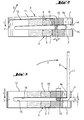
- Fig. 2
- eine Seitenansicht des in Fig. 1 dargestellten Schraubelements im gesicherten Zu- stand;
- Fig. 3
- eine Seitenansicht des in Fig. 1 dargestellten Schraubelements im ungesicherten Zustand.
Claims (10)
- Selbstsicherndes Schraubelement mit einem Klemmteil (1) und einem, zum Klemmteil (1) in axialem Abstand (a) angeordneten und durch einen Verbindungssteg (2) mit diesem verbundenen Hauptteil (3), wobei zum Eingriff in ein Gegengewinde, Hauptteil (3) und Klemmteil (1) von einem Gewinde (4) durchsetzt sind, dadurch gekennzeichnet, dass das Klemmteil (1) zumindest in Längsrichtung (L) des Gewindes (4) relativ zum Hauptteil (3) bewegbar ist.
- Schraubelement nach Anspruch 1, dadurch gekennzeichnet, dass das Klemmteil (1) zumindest in Längsrichtung (L) des Gewindes (4) relativ zum Hauptteil (3) verschwenkbar ist.
- Schraubelement nach Anspruch 2, dadurch gekennzeichnet, dass zum Verschwenken des Klemmteils (1) gegenüber dem Hauptteil (3) ein Spreizelement (8) vorgesehen ist.
- Schraubelement nach Anspruch 3, dadurch gekennzeichnet, dass das Spreizelement (8) zumindest teilweise zwischen dem Hauptteil (3) und dem Klemmteil (1) angeordnet ist.
- Schraubelement nach Anspruch 3 oder 4, dadurch gekennzeichnet, dass das Spreizelement (8) ein bolzenförmiges Spreizteil (13) aufweist.
- Schraubelement nach Anspruch 5, dadurch gekennzeichnet, dass das Spreizteil (13) quer zur Längsrichtung (L) des Gewindes (4) verläuft.
- Schraubelement nach Anspruch 5 oder 6, dadurch gekennzeichnet, dass das Spreizteil (13) quer zur Längsrichtung (L) des Gewindes (4) verdrehbar ist.
- Schraubelement nach einem der Ansprüche 5 bis 7, dadurch gekennzeichnet, dass das Spreizteil (13) einen unrunden Querschnitt aufweist.
- Schraubelement nach einem der Ansprüche 5 bis 8, dadurch gekennzeichnet, dass das Spreizelement (8) ein Betätigungsteil (11) zum Verdrehen des Spreizteils (13) aufweist.
- Schraubelement nach einem der Ansprüche 1 bis 9, dadurch gekennzeichnet, dass das Hauptteil (3), das Klemmteil (1) und der Verbindungssteg (2) zusammen einteilig ausgebildet sind.
Applications Claiming Priority (2)
| Application Number | Priority Date | Filing Date | Title |
|---|---|---|---|
| DE10161026A DE10161026A1 (de) | 2001-12-12 | 2001-12-12 | Selbstsicherndes Schraubelement |
| DE10161026 | 2001-12-12 |
Publications (3)
| Publication Number | Publication Date |
|---|---|
| EP1319850A2 true EP1319850A2 (de) | 2003-06-18 |
| EP1319850A3 EP1319850A3 (de) | 2003-08-20 |
| EP1319850B1 EP1319850B1 (de) | 2006-04-26 |
Family
ID=7708931
Family Applications (1)
| Application Number | Title | Priority Date | Filing Date |
|---|---|---|---|
| EP02027221A Expired - Lifetime EP1319850B1 (de) | 2001-12-12 | 2002-12-06 | Selbstsicherndes Schraubelement |
Country Status (7)
| Country | Link |
|---|---|
| US (1) | US6851905B2 (de) |
| EP (1) | EP1319850B1 (de) |
| AT (1) | ATE324528T1 (de) |
| DE (2) | DE10161026A1 (de) |
| DK (1) | DK1319850T3 (de) |
| ES (1) | ES2261584T3 (de) |
| PL (1) | PL202861B1 (de) |
Families Citing this family (9)
| Publication number | Priority date | Publication date | Assignee | Title |
|---|---|---|---|---|
| DE10343753B4 (de) * | 2003-09-22 | 2006-03-30 | Hilti Ag | Selbstsicherndes Schraubelement |
| DE102004003183A1 (de) * | 2004-01-22 | 2005-09-01 | Spieth-Maschinenelemente Gmbh & Co.Kg | Gewindering |
| GB0402274D0 (en) * | 2004-02-03 | 2004-03-10 | Hydratight Sweeney Ltd | Split nut |
| KR20050111219A (ko) * | 2004-05-21 | 2005-11-24 | 가부시키가이샤 에코 월드 | 이완 방지 너트와 그 제조방법 |
| US8087977B2 (en) | 2005-05-13 | 2012-01-03 | Black & Decker Inc. | Angle grinder |
| US7568873B1 (en) * | 2006-04-03 | 2009-08-04 | Rambo Ross W | Wrenchless nut device |
| DE102010032752A1 (de) * | 2010-07-29 | 2012-02-02 | Neumayer Tekfor Holding Gmbh | Befestigungselement |
| CN104500540B (zh) * | 2014-12-19 | 2016-11-09 | 苏州市淞舜五金有限公司 | 一种自动弹性防松螺栓 |
| US10818450B2 (en) | 2017-06-14 | 2020-10-27 | Black & Decker Inc. | Paddle switch |
Citations (1)
| Publication number | Priority date | Publication date | Assignee | Title |
|---|---|---|---|---|
| DE4034445A1 (de) | 1989-10-28 | 1992-08-27 | Hubert K Block | Selbstsichernde einstueckige schraubenelemente |
Family Cites Families (17)
| Publication number | Priority date | Publication date | Assignee | Title |
|---|---|---|---|---|
| US609144A (en) * | 1898-08-16 | Edgar alfred goddin | ||
| US171898A (en) * | 1876-01-04 | Improvement in nut-locks | ||
| US1448952A (en) * | 1922-02-06 | 1923-03-20 | George L Briese | Lock nut |
| FR850193A (fr) * | 1939-02-11 | 1939-12-09 | écrou indesserrable | |
| US2391712A (en) * | 1942-12-15 | 1945-12-25 | Ronald D King | Method of making self-locking nuts |
| US2421254A (en) * | 1944-08-24 | 1947-05-27 | Torrington Mfg Co | Wheel and shaft assembly means |
| US2409204A (en) * | 1945-08-18 | 1946-10-15 | James E Gall | Shaft locking device |
| US2472421A (en) * | 1945-11-07 | 1949-06-07 | Hamill William Wilson | Means for attaching wheels to shafts |
| FR950562A (fr) * | 1947-02-04 | 1949-09-30 | Procédé et dispositif pour la mise en place et l'enlèvement de l'écrou indesserrable | |
| BE563897A (de) * | 1957-01-18 | |||
| DE1149578B (de) * | 1960-03-26 | 1963-05-30 | Walter Engelmann | Sicherungsmutter |
| US3939889A (en) * | 1974-05-08 | 1976-02-24 | Ford Motor Company | Threaded assembly |
| SE385105B (sv) * | 1974-09-23 | 1976-06-08 | Bromsregulator Svenska Ab | Bromsaktuator |
| JPH039111A (ja) * | 1989-06-07 | 1991-01-17 | Masaaki Masuda | ゆるまないナット |
| US5907983A (en) * | 1997-09-08 | 1999-06-01 | Spirer; Steven E. | Stud remover |
| US5915902A (en) * | 1997-09-19 | 1999-06-29 | Illinois Tool Works Inc. | Undeformed lock nut with slot |
| DE10052445A1 (de) * | 2000-10-23 | 2002-05-02 | Hilti Ag | Schnellmontagemutter |
-
2001
- 2001-12-12 DE DE10161026A patent/DE10161026A1/de not_active Withdrawn
-
2002
- 2002-12-06 AT AT02027221T patent/ATE324528T1/de active
- 2002-12-06 DE DE50206547T patent/DE50206547D1/de not_active Expired - Lifetime
- 2002-12-06 EP EP02027221A patent/EP1319850B1/de not_active Expired - Lifetime
- 2002-12-06 ES ES02027221T patent/ES2261584T3/es not_active Expired - Lifetime
- 2002-12-06 DK DK02027221T patent/DK1319850T3/da active
- 2002-12-09 PL PL357631A patent/PL202861B1/pl unknown
- 2002-12-12 US US10/319,702 patent/US6851905B2/en not_active Expired - Lifetime
Patent Citations (1)
| Publication number | Priority date | Publication date | Assignee | Title |
|---|---|---|---|---|
| DE4034445A1 (de) | 1989-10-28 | 1992-08-27 | Hubert K Block | Selbstsichernde einstueckige schraubenelemente |
Also Published As
| Publication number | Publication date |
|---|---|
| DE10161026A1 (de) | 2003-06-26 |
| ATE324528T1 (de) | 2006-05-15 |
| DE50206547D1 (de) | 2006-06-01 |
| PL357631A1 (en) | 2003-06-16 |
| DK1319850T3 (da) | 2006-08-14 |
| ES2261584T3 (es) | 2006-11-16 |
| EP1319850B1 (de) | 2006-04-26 |
| EP1319850A3 (de) | 2003-08-20 |
| US6851905B2 (en) | 2005-02-08 |
| US20030147719A1 (en) | 2003-08-07 |
| PL202861B1 (pl) | 2009-07-31 |
Similar Documents
| Publication | Publication Date | Title |
|---|---|---|
| DD284073A5 (de) | Spannsatz | |
| WO1994007040A1 (de) | Vorrichtung zum verbinden von wenigstens zwei elementen | |
| WO1992012355A1 (de) | Kupplungselement zum kraftschlüssigen verbinden eines äusseren bauteils mit einer welle | |
| WO2014177237A1 (de) | Drehriegelverschluss | |
| WO2005030065A1 (de) | Vorrichtung zur verbindung eines längsträgers mit einem knochen | |
| EP0521490B1 (de) | Anordnung aus zwei teleskopisch miteinander verbundenen Bauelementen | |
| EP1319850A2 (de) | Selbstsicherndes Schraubelement | |
| EP0275441B1 (de) | Spannvorrichtung | |
| DE4231320C2 (de) | Vorrichtung zum lösbaren Verbinden von mindestens zwei Gegenständen | |
| DE102017127750A1 (de) | Drahtgewindeeinsatz | |
| EP1214239A1 (de) | Kippstiftmechanismus zum klemmen einer verstellbaren lenksäule | |
| EP2102509B1 (de) | Zuganker und damit zusammengespannte modulanordnung | |
| DE19529901A1 (de) | Knochenschraube | |
| DE102005015348A1 (de) | Haltevorrichtung für Teile eines Kraftfahrzeugs | |
| EP1896219B1 (de) | Verbindungsstelle | |
| EP3412388B1 (de) | Innenspannmittel mit gesichertem spannsegmentring | |
| DE4316808C2 (de) | Spannstück für Rohrelemente | |
| EP0344424B1 (de) | Drehverschluss | |
| EP0461465A1 (de) | Vorrichtung zur Befestigung von aktiven und/oder passiven Elementen an der Wandung von Komposit-Bauteilen | |
| EP4012200B1 (de) | Federbelasteter rastbolzen | |
| EP3282058A1 (de) | Vorrichtung zur befestigung eines sanitären bauteils, insbesondere eines befestigungsrahmens für eine wc- oder urinal-betätigungsplatte | |
| AT377312B (de) | Drueckerstift | |
| DE10050143A1 (de) | Bolzensicherung | |
| EP0523401B1 (de) | Türsicherung für ein mit einem Türfeststeller baulich vereinigtes Türscharnier | |
| DE1957480C3 (de) | Gelenkverbindung |
Legal Events
| Date | Code | Title | Description |
|---|---|---|---|
| PUAI | Public reference made under article 153(3) epc to a published international application that has entered the european phase |
Free format text: ORIGINAL CODE: 0009012 |
|
| AK | Designated contracting states |
Designated state(s): AT BE BG CH CY CZ DE DK EE ES FI FR GB GR IE IT LI LU MC NL PT SE SI SK TR |
|
| AX | Request for extension of the european patent |
Extension state: AL LT LV MK RO |
|
| PUAL | Search report despatched |
Free format text: ORIGINAL CODE: 0009013 |
|
| AK | Designated contracting states |
Designated state(s): AT BE BG CH CY CZ DE DK EE ES FI FR GB GR IE IT LI LU MC NL PT SE SI SK TR |
|
| AX | Request for extension of the european patent |
Extension state: AL LT LV MK RO |
|
| 17P | Request for examination filed |
Effective date: 20040220 |
|
| AKX | Designation fees paid |
Designated state(s): AT BE BG CH CY CZ DE DK EE ES FI FR GB GR IE IT LI LU MC NL PT SE SI SK TR |
|
| 17Q | First examination report despatched |
Effective date: 20050510 |
|
| GRAP | Despatch of communication of intention to grant a patent |
Free format text: ORIGINAL CODE: EPIDOSNIGR1 |
|
| GRAS | Grant fee paid |
Free format text: ORIGINAL CODE: EPIDOSNIGR3 |
|
| GRAA | (expected) grant |
Free format text: ORIGINAL CODE: 0009210 |
|
| AK | Designated contracting states |
Kind code of ref document: B1 Designated state(s): AT BE BG CH CY CZ DE DK EE ES FI FR GB GR IE IT LI LU MC NL PT SE SI SK TR |
|
| PG25 | Lapsed in a contracting state [announced via postgrant information from national office to epo] |
Ref country code: IE Free format text: LAPSE BECAUSE OF FAILURE TO SUBMIT A TRANSLATION OF THE DESCRIPTION OR TO PAY THE FEE WITHIN THE PRESCRIBED TIME-LIMIT Effective date: 20060426 Ref country code: CZ Free format text: LAPSE BECAUSE OF FAILURE TO SUBMIT A TRANSLATION OF THE DESCRIPTION OR TO PAY THE FEE WITHIN THE PRESCRIBED TIME-LIMIT Effective date: 20060426 Ref country code: SK Free format text: LAPSE BECAUSE OF FAILURE TO SUBMIT A TRANSLATION OF THE DESCRIPTION OR TO PAY THE FEE WITHIN THE PRESCRIBED TIME-LIMIT Effective date: 20060426 Ref country code: SI Free format text: LAPSE BECAUSE OF FAILURE TO SUBMIT A TRANSLATION OF THE DESCRIPTION OR TO PAY THE FEE WITHIN THE PRESCRIBED TIME-LIMIT Effective date: 20060426 Ref country code: FI Free format text: LAPSE BECAUSE OF FAILURE TO SUBMIT A TRANSLATION OF THE DESCRIPTION OR TO PAY THE FEE WITHIN THE PRESCRIBED TIME-LIMIT Effective date: 20060426 |
|
| REG | Reference to a national code |
Ref country code: GB Ref legal event code: FG4D Free format text: NOT ENGLISH |
|
| REG | Reference to a national code |
Ref country code: SE Ref legal event code: TRGR |
|
| REG | Reference to a national code |
Ref country code: IE Ref legal event code: FG4D Free format text: LANGUAGE OF EP DOCUMENT: GERMAN |
|
| REF | Corresponds to: |
Ref document number: 50206547 Country of ref document: DE Date of ref document: 20060601 Kind code of ref document: P |
|
| GBT | Gb: translation of ep patent filed (gb section 77(6)(a)/1977) |
Effective date: 20060526 |
|
| REG | Reference to a national code |
Ref country code: DK Ref legal event code: T3 |
|
| PG25 | Lapsed in a contracting state [announced via postgrant information from national office to epo] |
Ref country code: PT Free format text: LAPSE BECAUSE OF FAILURE TO SUBMIT A TRANSLATION OF THE DESCRIPTION OR TO PAY THE FEE WITHIN THE PRESCRIBED TIME-LIMIT Effective date: 20060926 |
|
| REG | Reference to a national code |
Ref country code: IE Ref legal event code: FD4D |
|
| REG | Reference to a national code |
Ref country code: ES Ref legal event code: FG2A Ref document number: 2261584 Country of ref document: ES Kind code of ref document: T3 |
|
| ET | Fr: translation filed | ||
| PG25 | Lapsed in a contracting state [announced via postgrant information from national office to epo] |
Ref country code: MC Free format text: LAPSE BECAUSE OF NON-PAYMENT OF DUE FEES Effective date: 20061231 |
|
| PLBE | No opposition filed within time limit |
Free format text: ORIGINAL CODE: 0009261 |
|
| STAA | Information on the status of an ep patent application or granted ep patent |
Free format text: STATUS: NO OPPOSITION FILED WITHIN TIME LIMIT |
|
| 26N | No opposition filed |
Effective date: 20070129 |
|
| PG25 | Lapsed in a contracting state [announced via postgrant information from national office to epo] |
Ref country code: GR Free format text: LAPSE BECAUSE OF FAILURE TO SUBMIT A TRANSLATION OF THE DESCRIPTION OR TO PAY THE FEE WITHIN THE PRESCRIBED TIME-LIMIT Effective date: 20060727 |
|
| PG25 | Lapsed in a contracting state [announced via postgrant information from national office to epo] |
Ref country code: BG Free format text: LAPSE BECAUSE OF FAILURE TO SUBMIT A TRANSLATION OF THE DESCRIPTION OR TO PAY THE FEE WITHIN THE PRESCRIBED TIME-LIMIT Effective date: 20060726 Ref country code: EE Free format text: LAPSE BECAUSE OF FAILURE TO SUBMIT A TRANSLATION OF THE DESCRIPTION OR TO PAY THE FEE WITHIN THE PRESCRIBED TIME-LIMIT Effective date: 20060426 |
|
| PG25 | Lapsed in a contracting state [announced via postgrant information from national office to epo] |
Ref country code: TR Free format text: LAPSE BECAUSE OF FAILURE TO SUBMIT A TRANSLATION OF THE DESCRIPTION OR TO PAY THE FEE WITHIN THE PRESCRIBED TIME-LIMIT Effective date: 20060426 Ref country code: LU Free format text: LAPSE BECAUSE OF NON-PAYMENT OF DUE FEES Effective date: 20061206 |
|
| PG25 | Lapsed in a contracting state [announced via postgrant information from national office to epo] |
Ref country code: CY Free format text: LAPSE BECAUSE OF FAILURE TO SUBMIT A TRANSLATION OF THE DESCRIPTION OR TO PAY THE FEE WITHIN THE PRESCRIBED TIME-LIMIT Effective date: 20060426 |
|
| REG | Reference to a national code |
Ref country code: FR Ref legal event code: PLFP Year of fee payment: 14 |
|
| PGFP | Annual fee paid to national office [announced via postgrant information from national office to epo] |
Ref country code: GB Payment date: 20151202 Year of fee payment: 14 Ref country code: CH Payment date: 20151211 Year of fee payment: 14 Ref country code: DK Payment date: 20151210 Year of fee payment: 14 Ref country code: DE Payment date: 20151201 Year of fee payment: 14 |
|
| PGFP | Annual fee paid to national office [announced via postgrant information from national office to epo] |
Ref country code: ES Payment date: 20151111 Year of fee payment: 14 Ref country code: AT Payment date: 20151125 Year of fee payment: 14 Ref country code: BE Payment date: 20151207 Year of fee payment: 14 Ref country code: NL Payment date: 20151210 Year of fee payment: 14 Ref country code: SE Payment date: 20151211 Year of fee payment: 14 Ref country code: FR Payment date: 20151110 Year of fee payment: 14 |
|
| PGFP | Annual fee paid to national office [announced via postgrant information from national office to epo] |
Ref country code: IT Payment date: 20151221 Year of fee payment: 14 |
|
| PG25 | Lapsed in a contracting state [announced via postgrant information from national office to epo] |
Ref country code: BE Free format text: LAPSE BECAUSE OF NON-PAYMENT OF DUE FEES Effective date: 20161231 |
|
| REG | Reference to a national code |
Ref country code: DE Ref legal event code: R119 Ref document number: 50206547 Country of ref document: DE |
|
| REG | Reference to a national code |
Ref country code: DK Ref legal event code: EBP Effective date: 20161231 Ref country code: CH Ref legal event code: PL |
|
| REG | Reference to a national code |
Ref country code: SE Ref legal event code: EUG |
|
| REG | Reference to a national code |
Ref country code: NL Ref legal event code: MM Effective date: 20170101 |
|
| REG | Reference to a national code |
Ref country code: AT Ref legal event code: MM01 Ref document number: 324528 Country of ref document: AT Kind code of ref document: T Effective date: 20161206 |
|
| GBPC | Gb: european patent ceased through non-payment of renewal fee |
Effective date: 20161206 |
|
| PG25 | Lapsed in a contracting state [announced via postgrant information from national office to epo] |
Ref country code: SE Free format text: LAPSE BECAUSE OF NON-PAYMENT OF DUE FEES Effective date: 20161207 |
|
| PG25 | Lapsed in a contracting state [announced via postgrant information from national office to epo] |
Ref country code: NL Free format text: LAPSE BECAUSE OF NON-PAYMENT OF DUE FEES Effective date: 20170101 |
|
| REG | Reference to a national code |
Ref country code: FR Ref legal event code: ST Effective date: 20170831 |
|
| PG25 | Lapsed in a contracting state [announced via postgrant information from national office to epo] |
Ref country code: AT Free format text: LAPSE BECAUSE OF NON-PAYMENT OF DUE FEES Effective date: 20161206 Ref country code: IT Free format text: LAPSE BECAUSE OF NON-PAYMENT OF DUE FEES Effective date: 20161206 Ref country code: CH Free format text: LAPSE BECAUSE OF NON-PAYMENT OF DUE FEES Effective date: 20161231 Ref country code: LI Free format text: LAPSE BECAUSE OF NON-PAYMENT OF DUE FEES Effective date: 20161231 Ref country code: FR Free format text: LAPSE BECAUSE OF NON-PAYMENT OF DUE FEES Effective date: 20170102 |
|
| PG25 | Lapsed in a contracting state [announced via postgrant information from national office to epo] |
Ref country code: GB Free format text: LAPSE BECAUSE OF NON-PAYMENT OF DUE FEES Effective date: 20161206 Ref country code: DE Free format text: LAPSE BECAUSE OF NON-PAYMENT OF DUE FEES Effective date: 20170701 |
|
| PG25 | Lapsed in a contracting state [announced via postgrant information from national office to epo] |
Ref country code: DK Free format text: LAPSE BECAUSE OF NON-PAYMENT OF DUE FEES Effective date: 20161231 |
|
| REG | Reference to a national code |
Ref country code: BE Ref legal event code: MM Effective date: 20161231 |
|
| PG25 | Lapsed in a contracting state [announced via postgrant information from national office to epo] |
Ref country code: ES Free format text: LAPSE BECAUSE OF FAILURE TO SUBMIT A TRANSLATION OF THE DESCRIPTION OR TO PAY THE FEE WITHIN THE PRESCRIBED TIME-LIMIT Effective date: 20060426 |
|
| REG | Reference to a national code |
Ref country code: ES Ref legal event code: FD2A Effective date: 20181116 |
|
| PG25 | Lapsed in a contracting state [announced via postgrant information from national office to epo] |
Ref country code: ES Free format text: LAPSE BECAUSE OF FAILURE TO SUBMIT A TRANSLATION OF THE DESCRIPTION OR TO PAY THE FEE WITHIN THE PRESCRIBED TIME-LIMIT Effective date: 20161207 |