EP1319793A1 - Safety device for cord operated control system - Google Patents
Safety device for cord operated control system Download PDFInfo
- Publication number
- EP1319793A1 EP1319793A1 EP02258681A EP02258681A EP1319793A1 EP 1319793 A1 EP1319793 A1 EP 1319793A1 EP 02258681 A EP02258681 A EP 02258681A EP 02258681 A EP02258681 A EP 02258681A EP 1319793 A1 EP1319793 A1 EP 1319793A1
- Authority
- EP
- European Patent Office
- Prior art keywords
- drive wheel
- housing
- control system
- portions
- cord
- Prior art date
- Legal status (The legal status is an assumption and is not a legal conclusion. Google has not performed a legal analysis and makes no representation as to the accuracy of the status listed.)
- Granted
Links
- 230000000295 complement effect Effects 0.000 claims description 17
- 239000011324 bead Substances 0.000 description 5
- 210000003414 extremity Anatomy 0.000 description 2
- 210000001364 upper extremity Anatomy 0.000 description 2
- 208000027418 Wounds and injury Diseases 0.000 description 1
- 230000008859 change Effects 0.000 description 1
- 238000010276 construction Methods 0.000 description 1
- 230000006378 damage Effects 0.000 description 1
- 208000014674 injury Diseases 0.000 description 1
- 230000007794 irritation Effects 0.000 description 1
- 239000000463 material Substances 0.000 description 1
- 238000000034 method Methods 0.000 description 1
- 230000007935 neutral effect Effects 0.000 description 1
- 230000008569 process Effects 0.000 description 1
- 230000001105 regulatory effect Effects 0.000 description 1
- 230000004044 response Effects 0.000 description 1
Images


Classifications
-
- E—FIXED CONSTRUCTIONS
- E06—DOORS, WINDOWS, SHUTTERS, OR ROLLER BLINDS IN GENERAL; LADDERS
- E06B—FIXED OR MOVABLE CLOSURES FOR OPENINGS IN BUILDINGS, VEHICLES, FENCES OR LIKE ENCLOSURES IN GENERAL, e.g. DOORS, WINDOWS, BLINDS, GATES
- E06B9/00—Screening or protective devices for wall or similar openings, with or without operating or securing mechanisms; Closures of similar construction
- E06B9/24—Screens or other constructions affording protection against light, especially against sunshine; Similar screens for privacy or appearance; Slat blinds
- E06B9/26—Lamellar or like blinds, e.g. venetian blinds
- E06B9/28—Lamellar or like blinds, e.g. venetian blinds with horizontal lamellae, e.g. non-liftable
- E06B9/30—Lamellar or like blinds, e.g. venetian blinds with horizontal lamellae, e.g. non-liftable liftable
- E06B9/32—Operating, guiding, or securing devices therefor
- E06B9/322—Details of operating devices, e.g. pulleys, brakes, spring drums, drives
-
- E—FIXED CONSTRUCTIONS
- E06—DOORS, WINDOWS, SHUTTERS, OR ROLLER BLINDS IN GENERAL; LADDERS
- E06B—FIXED OR MOVABLE CLOSURES FOR OPENINGS IN BUILDINGS, VEHICLES, FENCES OR LIKE ENCLOSURES IN GENERAL, e.g. DOORS, WINDOWS, BLINDS, GATES
- E06B9/00—Screening or protective devices for wall or similar openings, with or without operating or securing mechanisms; Closures of similar construction
- E06B9/24—Screens or other constructions affording protection against light, especially against sunshine; Similar screens for privacy or appearance; Slat blinds
- E06B9/26—Lamellar or like blinds, e.g. venetian blinds
- E06B9/28—Lamellar or like blinds, e.g. venetian blinds with horizontal lamellae, e.g. non-liftable
- E06B9/30—Lamellar or like blinds, e.g. venetian blinds with horizontal lamellae, e.g. non-liftable liftable
- E06B9/32—Operating, guiding, or securing devices therefor
- E06B9/326—Details of cords, e.g. buckles, drawing knobs
- E06B2009/3265—Emergency release to prevent strangulation or excessive load
Definitions
- This invention relates generally to a control system for operating and positioning a covering for an architectural opening, such as a window blind (e.g., a horizontal or vertical venetian blind).
- a control system which includes a drive wheel for positioning a blind and an endless-loop operating cord, looped over the drive wheel, so that depending portions of the cord are on opposite sides of the drive wheel.
- This invention quite particularly relates to a safety device for such a control system that includes means for allowing the cord to be detached from the drive wheel when a generally downward force is exerted simultaneously on both depending portions of the cord.
- EP 0 869 254 Means for releasing an endless-loop operating cord, in its entirety, from a control system of a window blind to ensure the safety of children that might become entangled in the cord are described in EP 0 869 254.
- the operating cord of EP 0 869 254 depends from opposite sides of a drive wheel but is not looped over the drive wheel. Rather, its operating cord is slidably attached to a mounting plate, which is releasably mounted on a mounting support, and the cord is kept in operative engagement with the lower half of the drive wheel by the mounting plate. When both depending portions of the cord are pulled at the same time, the mounting plate is released from the mounting support, thereby releasing the cord from the control system, thereby preventing possible injury to a child whose head may have become entangled in the cord.
- a cord-operated control system for a covering for an architectural opening which includes:
- the second drive wheel is operatively connected to the first drive wheel by a third drive wheel and an auxiliary operating cord.
- both the second drive wheel and the third drive wheel are rotatably mounted in the housing, the auxiliary drive cord is an endless loop and is looped over the first drive wheel and the third drive wheel to operatively connect them, and wherein, when the second drive wheel is rotated, it causes the third drive wheel to rotate, which in turn causes the auxiliary operating cord to drive the first drive wheel to rotate and thus causes the driven member to rotate.
- the release means are for disconnecting a lower portion of the housing with a drive wheel from an upper portion of the housing with another drive wheel.
- the release means comprises a releasable snap engagement arrangement between the lower and upper housing portions.
- the second and third drive wheels are coaxially connected, and the release means are for disconnecting the coaxially-connected, second and third drive wheels.
- the release means comprises a releasable snap fit arrangement between the second and third drive wheels.
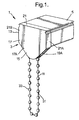
- Figures 1 and 2 show a control system 1 of this invention in a housing 3, mounted as an end cap on a longitudinally-extending head rail 5 of a venetian blind (not shown).
- the control system 1 includes a first or upper drive wheel 7, a second or lower drive wheel 9 and a conventional closed loop or endless-loop, operating cord 11, such as a bead chain, which functions as an operating element of the blind.
- the upper drive wheel 7 is operatively connected to a conventional, longitudinally-extending, driven member 5A, rotation of which causes movement of the blind, such as a traversing, lifting and/or tilting movement of the blind slats.
- the driven member 5A can be a conventional drive shaft of a roller blind, central control shaft for a roman shade, lift or tilt shaft of a horizontal venetian blind or tilt shaft of a vertical venetian blind. Looped about the second drive wheel 9 is the operating cord 11.
- the housing 3, which accommodates the upper and lower, drive wheels 7,9, has an upper or first housing portion 13 and a lower or second housing portion 15.
- the upper housing portion 13 comprises an upstanding, laterally-extending, upper left (as shown in Figures 1-2) wall portion 17, remote from the head rail 5, and an upstanding, laterally-extending, upper right (as shown in Figures 1-2) wall portion 19, adjacent the head rail 5.
- the upper wall portions 17,19 are connected by a horizontally-extending top bridging wall member 21, atop the upper wall portions 17,19, and a pair of upstanding, front and back, bridging wall members 21A, 21B, at the lateral sides of the upper wall portions 17,19, thereby defining an upper space 23 between the upper wall portions 17,19 for accommodating the upper drive wheel 7.
- the upper housing portion 13 and the head rail 5 preferably have the same profile when viewed from a longitudinal end of the head rail.
- the lower housing portion 15 likewise comprises an upstanding, laterally-extending, lower left wall portion 17A and an upstanding, laterally-extending, lower right wall portion 19A.
- the lower wall portions 17A, 19A extend downwardly form the upper wall portions 17, 19 but are not connected by bridging wall members either on their lateral sides or on their top or bottom. However, by virtue of the top wall bridging member 21 and the front and back, bridging wall members 21A, 21B, a lower space 23A is defined between the lower wall portions 17A,19A, beneath the upper space 23.
- the lower space 23A accommodates the lower drive wheel 9 and the upper portions of the operating cord 11, passing laterally over the lower drive wheel.
- the laterally-extending width of each of the lower, left and right, wall portions 17A, 19A is gradually reduced from its top to its bottom, thus providing these wall portions with a generally semi-circular or triangular form with the narrowest part being the lowermost part.
- the lower left and right wall portions 17A,19A have equal laterally-extending widths that are somewhat greater than the laterally-extending width of the lower drive wheel.
- the upper and lower, left wall portions 17, 17A, and upper and lower, right wall portions 19 and 19A can be integrally shaped into respectively a left wall and a right wall.
- the upper and lower drive wheels 7, 9 are rotatably mounted in the housing 3 in a generally conventional manner, as described, for example, in US 6,158,563 or US 4,372,432.
- mounting journals or stub axles on opposite sides of the drive wheels 7, 9 or on the upper and lower wall portions 17, 17A, 19, 19A are rotatably accommodated in complementary coaxial bearings or journal bores in the wall portions or in opposite sides of the drive wheels, respectively.
- the upper drive wheel 7 be rotatably mounted as follows in the upper housing portion 13.
- the inner surface of the upper left wall portion 17 has a longitudinally-extending upper left bearing 24, in which is positioned a corresponding coaxial upper left journal 25, located at the center of the left side of the upper drive wheel 7.
- Extending longitudinally through the upper right wall portion 19 is an upper right bearing 26, which is coaxial with the upper left bearing 24, and extending longitudinally through the left side of the head rail 5 is a bearing 27 that is adjacent to, and coaxial, with the upper right bearing 26 and the driven member 5A.
- a corresponding coaxial upper right journal 28 Positioned in the adjacent bearings 26, 27 is a corresponding coaxial upper right journal 28.
- the upper right journal 28 is located at the center of the right side of the upper drive wheel 7 and is connected to the driven member 5A, so that the upper drive wheel and the driven member are operatively connected to rotate together.
- the lower drive wheel 9 be rotatably mounted in the lower housing portion 15.
- the inner surfaces of the lower, left and right wall portions 17A,19A have coaxial longitudinally-extending lower bearings 24A, in each of which is positioned one of a pair of corresponding coaxial lower journals 25A, located at the center of the left and right sides of the lower drive wheel 9.
- the upper drive wheel 7 is operatively connected to the lower drive wheel 9, so that rotation of the lower drive wheel 9 causes rotation of the upper drive wheel 7.
- the circumference of each of the drive wheels 7,9 is provided with gear teeth 29, 29A, respectively, and the gear teeth 29 of the upper drive wheel 7 interact with the gear teeth 29A of the lower drive wheel 9, so that the two drive wheels 7,9 rotate together.
- the lower drive wheel 9 is adapted to accommodate the operating cord 11 which is looped about and engages the circumference of the lower drive wheel.
- the lower drive wheel 9 can be a simple pulley for a cord or have an exterior rim that is specially shaped with a circumferential groove 30 to receive the operating cord 11.
- the operating cord 11 has two depending portions 31, 33 on laterally opposite sides of the lower drive wheel 9.
- each lower bearing 24A preferably has a beveled edge or rim and/or that each corresponding lower journal 25A has a beveled edge.
- the left and right walls 17, 17A, 19, 19A, particularly the lower, left and right, wall portions 17A,19A, of the housing 3 are relatively flexible and resilient. This relative flexibility and resilience are a function of the lack of bridging wall members between the lower wall portions 17A, 19A. This relative flexibility and resilience are also a function of the relative longitudinal thinness of one or preferably both of the lower, left and right lower wall portions 17A, 19A.
- the lower drive wheel 9 is normally held in place in the housing 3 -- so that the lower drive wheel is operatively connected to the upper drive wheel 7 and thereby to the rest of the control system 1 -- by the lower, left and right, wall portions 17A,19A of the housing 3 and by the engagement of the lower journals 25A with the lower bearings 24A.
- the lower journals 25A force the lower, left and right, wall portions 17A,19A slightly apart before the lower journals lodge in their respective lower bearings with the beveled edges of the lower journals bearing on the beveled rims of the lower bearings.
- the longitudinal width of the lower drive wheel 9 at its widest portion, including the beveled lower journals 25A, is slightly larger than the largest width of the lower space 23A of the lower housing portion 15.
- the largest width of the lower space 23A is preferably where the lower bearings 24A are located because this width includes the longitudinal depth of the lower bearings. Nevertheless, the largest width of the lower space 23A is still smaller than the widest part of the lower drive wheel 9 where the lower journals 25A are located.
- both the first and second cord portions 31, 33 are pulled downwardly simultaneously by a force that exceeds a predetermined value -- for example, in the unlikely event a child gets entangled in the bottom loop of the operating cord 11 -- the downward force on the operating cord produces a longitudinally outwardly-directed force acting through the beveled edges of both lower journals 25A bearing downwardly on the beveled rims of the lower bearings 24A.
- This longitudinally outwardly-directed force will cause the flexible, lower, left and right, wall portions 17A,19A, of the housing 3 to be pushed longitudinally apart from each other, and the lower wall portions may also be slightly bent temporarily by such force but without permanent bend lines forming in the lower wall portions.
- the lower drive wheel and operating cord can be pushed back into the housing 3 and operatively reconnected to the upper drive wheel and the rest of the control system 1. This can be done simply by pushing the lower drive wheel 9 with the operating cord 11 upwardly into the lower housing portion 15, so that its lower journals 25A are again in the lower bearings 24A. In this regard, pushing the lower journals 25A back into the lower bearings 24A is easier if the lower journals or the lower bearings or both have beveled edges.
- the design and construction of the elements of the control system 1 can be varied to vary the required amount of downward force, applied simultaneously to the first and second cord portions 31, 33, in order to disconnect the lower drive wheel 9 from the upper drive wheel 7.
- the angle of the beveled edges of the lower journals 25A, the angle of the beveled edges of the lower bearings 24A, the shape and dimensions of the lower journals and lower bearings and/or the relative flexibility and resilience of the left and right, wall portions 17A,19A, of the housing 3 can affect the amount of downward force on the first and second cord portions 31, 33 necessary to release the lower drive wheel 9 from engagement with the upper drive wheel 7.
- the more rigid the lower wall portions 17A,19A the more force required to release the lower drive wheel 9.
- both the edges of the lower bearings 24A and the lower journals 25A are beveled at a greater angle (relative to horizontal), less force is likely to be required to release the lower drive wheel 9.
- both the lower bearings 24A and the lower journals 25A are longitudinally longer, it will be more difficult to release the lower drive wheel 9.
- the thickness, as well as the choice of materials, of the housing 3, particularly its lower wall portions 17A,19A can be varied to vary the flexibility and resilience of the lower wall portions.
- conventional clutches and/or brakes for regulating the rotation of the driven member 5A, in response to rotation of the upper drive wheel 7 or the weight of the blind can be provided in the head rail 5.
- These can be of the type disclosed by, for example, US 4,372,432 and US 6,158,563.
- Figure 3 shows a second embodiment 101 of a control system of this invention which is similar to the control system 1 of Figures 1 and 2 and for which corresponding reference numerals (greater by 100) are used below for describing the same or corresponding parts.
- the control system 101 is in a housing 103, mounted as an end cap on a head rail 105 of a venetian blind (not shown).
- the control system 101 includes: an upper drive wheel (not shown), rotatably mounted in an upper portion 113 of the housing 103 and operatively connected to a driven member (not shown); a lower drive wheel 109, rotatably connected to a lower portion 115 of the housing 103 and operatively connected to the upper drive wheel; and an endless-loop, operating cord 111, looped over the lower drive wheel.
- each lower journal bore 124A has a keyhole shape that is open at the bottom of its lower wall portion 117A, 119A.
- each keyhole-shaped lower bearing 124A has an upper, generally circular portion 139 that has a diameter greater than each lower journal 125A and a lower, downwardly-extending, stem portion 141 that is open at the bottom.
- the circular portion 139 of each lower bearing 124A is adapted to hold one of the lower journals 125A of the lower drive wheel 109 during normal operation of the control system 101.
- the lateral sides of the stem portion 141 of each lower bearing 124A diverge laterally and downwardly from beneath the upper, circular portion 139 where the lateral sides are relatively close and form a restricted opening 143 in its lower wall portion 117A,119A at the upper end of the stem portion.
- the lateral width of this restricted opening 143 is preferably less than the diameter of each journal 125A.
- each tapered stem portion 141 of a lower bearing 124A form two fingers 145 on laterally-opposite sides of the of the lower bearing.
- the lower, left and right, wall portions 117A, 119A, particularly the fingers 145 are relatively flexible and resilient.
- each lower journal preferably has a circumferential groove (not shown) near its longitudinal end.
- the groove of each lower journal engages longitudinally the left and right sides of the adjacent lower wall portion 117A, 119A, about the circular portion of the lower bearing, in which the lower journal is held, and thereby prevents undesired longitudinal slippage of the lower drive wheel.
- a downward pulling force simultaneously on both the first and second depending portions 131, 133 of the operating cord 111 can pull the lower journals 125A of the lower drive wheel 109 downwardly, out of the circular portions 139 of the lower bearings 124A through their restricted openings 143, then through their stem portions 141 and finally out the bottom of the stem portions.
- the two flexible and resilient fingers 145 on each lower wall portion 117A, 119A will be pushed laterally apart in order to allow the lower journals 125A to move downwardly, past the restricted openings 143, and the fingers 145 may also be slightly bent temporarily by such downward movement of the lower journals but without permanent bend lines forming in the lower wall portions.
- the lower drive wheel 109 with the operating cord 111, can be pushed back into the housing 103 and operatively reconnected to the upper drive wheel (not shown) and the rest of the control system 101. This can be done simply by pushing the lower drive wheel 109 with the operating cord upwardly into the lower housing portion 115, past the two fingers 145 and the restricted openings 143, so that its lower journals 125A are again in the circular portions 139 of the lower bearings 124A.
- Figure 4 shows a third embodiment 201 of a control system of this invention which is similar to the control system 101 of Figure 3 and for which corresponding reference numerals (greater by 100) are used below for describing the same or corresponding parts.
- the control system 201 is in a housing 203, mounted as an end cap on a head rail 205 of a venetian blind (not shown).
- the control system 201 includes: an upper drive wheel 207, rotatably mounted in an upper portion 213 of the housing 203 and operatively connected to a driven member (not shown); a lower drive wheel 209, rotatably connected to a lower portion 215 of the housing 203 and operatively connected to the upper drive wheel; and an endless-loop, operating cord 211, looped over the lower drive wheel.
- each lower bearing 224A is formed as a blind recess with a longitudinally-extending, upper, generally circular hole 239 and a downwardly-extending stem portion or groove 241, connected to the circular hole.
- the circular hole 239 of each lower bearing 224A is deeper than its stem portion 241, in that its circular hole 239 extends longitudinally farther from the inner surface of its lower wall portion 217A (not shown), 219A than does its stem portion 241.
- the lower journals 225A or the lower bearings 224A especially both, have beveled edges.
- the portions of the circular holes 239 of the lower bearings 224A are adapted to accommodate and hold the lower journals 225A of the lower drive wheel 209 in the housing 203 during normal operation of the control system 201.
- the beveled edges of the lower journals 225A bear down on the beveled edges of the circular holes 239 of the lower bearings 224A .
- the lower drive wheel 209 with the operating cord 211, can be pushed back into the housing 203 and operatively reconnected to the upper drive wheel 207 and the rest of the control system 201. This can be done simply by pushing the lower drive wheel 209 with the operating cord upwardly into the lower housing portion 215, along the stem portions 241 of the lower bearings 224A, so that its lower journals 225A are again in the circular portions 239 of the lower bearings.
- FIGS 5 and 6 show a fourth embodiment 301 of the control system of this invention which is similar to the control system of 201 of Figure 4 and for which corresponding reference numerals (greater by 100) are used for describing the same or corresponding parts.
- the control system 301 features a third or intermediate drive wheel 347 and a second or auxiliary drive cord 349.
- the housing 303 which is the main housing of the control system 301, holds a rotatable lower drive wheel 309 and the rotatable intermediate drive wheel 347.
- a rotatable upper drive wheel 307 is provided in a fixed auxiliary housing 351 connected to a head rail 305 of a venetian blind.
- the auxiliary housing 351 has an upstanding, laterally-extending, left wall 353, remote from the head rail 305, and an opposite upstanding laterally-extending, right wall 355, adjacent to or integral with the head rail.
- the left and right walls 353, 355 of the auxiliary housing are connected by a horizontally-extending top wall member 357, atop the left and right walls, and by a pair of upstanding front and back, side bridging wall members 359, 361 at the lateral sides of the left and right walls.
- the upper drive wheel 307 has left and right, upper journals 325 and 328 that protrude from its opposite lateral side and are rotatably carried in, respectively, a left upper bearing 324 in the left wall 353 of the auxiliary housing 351 and a right upper bearing 328 in the right wall 355 of the auxiliary housing.
- the main housing 303 carrying the lower drive wheel 309, is attached to the upper drive wheel 307 by an endless-loop auxiliary drive cord 349 that is looped about and engages the circumference of both the intermediate drive wheel 347 and the upper drive wheel 307.
- the housing 303 can thus be easily retrofitted to an existing blind with an upper drive wheel 307.
- the main housing 303 has an upper portion 313, in which the intermediate drive wheel 347 is mounted, and a lower portion 315, in which the lower drive wheel 309 is mounted.
- the lower drive wheel 309 is operatively connected to the upper drive wheel 307 by means of the intermediate drive wheel 347 and the auxiliary drive cord 349, so that rotation of the lower drive wheel 309 causes rotation of the intermediate drive wheel, which in turn causes rotation of the upper drive wheel.
- the lower drive wheel 309 can be rotated by pulling either one of the depending portions 331, 333 of the main drive cord 311 that is looped over it.
- the upper portion 313 of the housing 303 includes a pair of opposite, upstanding, laterally-extending, left and right, upper wall portions 317, 319, and similarly, the lower portion 315 of the housing 303 includes a pair of opposite, upstanding, laterally-extending, left and right, lower wall portions 317A, 319A.
- the upper and lower, wall portions are integral with each other, the lower wall portions 317A 319A extending downward from the upper wall portions 317, 319 and the lower end of the upper wall portions contacting the upper end of the lower wall portions.
- the opposite wall portions 317, 319, 317A, 319A are connected by a pair of upstanding, front and back, bridging wall members 321A, 321B.
- the side bridging wall members extend longitudinally between the opposite wall portions. As shown in Figure 5, the side bridging wall members can be relatively short, leaving unconnected large portions of the front and back of the upper and lower housing portions 313, 315.
- the inner surfaces of the lower wall portions 317A (not shown), 319A of the main housing 303 each have a longitudinally-extending lower bearing 324A that is complementary to, and carries, a corresponding longitudinally-extending lower journal 325A protruding from left and right sides of the lower drive wheel 309.
- Each lower bearing 324A is formed as a circular blind hole 339.
- the lower journals 325A or the lower bearings 324A, or both have beveled edges.
- the blind holes 339 of the lower bearings 324A are adapted to accommodate and hold the lower journals 325A of the lower drive wheel 309 in the lower portion 315 of the housing 303 during normal operation of the control system 301.
- intermediate journals 363 Protruding from left and right sides of the intermediate drive wheel 347 are longitudinally-extending intermediate journals 363 that are complementary to and carried by, longitudinally-extending intermediate bearings 365 in the inner surfaces of the upper wall portions 317, 319 of the main housing 303.
- the intermediate bearings 365 are adapted to accommodate and hold the intermediate journals 325A of the intermediate drive wheel 347 in the upper portion 313 of the housing 303.
- FIG. 7 shows a fifth embodiment 401 of a control system of this invention which is similar to the control system of 301 of Figures 5 and 6 and for which corresponding reference numerals (greater by 100) are used for describing the same or corresponding parts.
- the control system 401 includes a main housing 403 with an intermediate drive wheel 447, a detachable lower drive wheel 409, and an auxiliary drive cord 449.
- the auxiliary drive cord 449 is looped about the intermediate drive wheel 447 and the upper drive wheel, and an operating cord 411 is looped about the lower drive wheel 409.
- a pair of small parallel intermediate pinion wheels 467, 469 are mounted in the housing 403 between the lower drive wheel 409 and the intermediate drive wheel 447.
- the pinion wheels 467, 469 operatively connect the lower drive wheel to the intermediate drive wheel, so that when either of the depending portions 431 or 433 of the operating cord 411 is pulled downwardly, the upper drive wheel 407 (not shown) will rotate in the same direction as the lower drive wheel.
- the bridging wall members 421A, 421B of the housing 403 are provided with an inwardly facing contour which allows the pinion wheels 467, 469 to be mounted within the housing 403.
- the height of the housing 403 is preferably somewhat greater than that of the corresponding housing 303 of the control system 301 of Figures 5 and 6 in order to accommodate the pinion wheels.
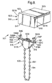
- FIG. 8-10 shows a sixth embodiment 501 of the control system of this invention which is similar to the control system 101 of Figure 1 and for which corresponding reference numerals (greater by 500) are used for describing the same or corresponding parts.
- Upper and lower drive wheels 507, 509 are rotatably mounted in upper and lower portions 513, 515 of housing 503 and are operatively engaged to each other.
- the upper housing portion 513 is attached to blind head rail 505, and the lower housing portion 515 is releasably attached to the upper housing portion, preferably by a releasable snap engagement, as described below.
- the upper housing portion 513 has upstanding, front and back, bridging wall members 521 A, 521 B, the inner surfaces of which have front and back slots 571, 573 facing each other.
- the slots extend longitudinally across the width of the upper bridging wall members and are relatively close to bottom surfaces 575, 577 thereof.
- the inner surfaces of the upper bridging wall members 521A, 521B have upstanding intermediate surfaces portions 579, 581.
- the slots 571, 573 each have an outwardly-extending, slightly sloped ledge 571A, 573A, above which is preferably an upstanding intermediate portion 571 B, 573B, and above which is an inwardly-extending gentle ramp 571 C, 573C.
- the lower housing portion 515 has upstanding, front and back, bridging wall members 521C, 521D.
- On top surfaces 591, 593 of the lower bridging wall members 521C and 521D are cantilever beams 583, 585 which extend upwardly and longitudinally.
- At the top of each cantilever beam is a snap-lug 587, 589.
- the cantilever beams 583, 585 can flex laterally inwardly, towards each other, when the upper and lower housing portions 513, 515 are urged vertically together to attach them to each other as shown in Figure 10.
- the cantilever beams 583, 585 are also resilient and can flex back laterally outwardly, away from each other, when the snap-lugs 587, 589 snap into the slots 571, 573 of the upper bridging wall members 521A, 521B of the upper housing portion 513.
- the snap-lugs 587, 589 have a generally triangular shape and extend laterally outwardly away from each other.
- each snap-lug has a gentle entrance ramp 587C, 589C at its top or entrance side, a sharper angled retraction ramp 587A,589A at its bottom or retraction side, and preferably an upstanding intermediate portion 587B, 589B between them.
- each intermediate snap-lug portion 587B, 589B is adapted to fit in an intermediate slot portion 571 B, 573B in the upper housing portion 513 when the upper and lower housing portions are attached to each other as shown in Figure 10, but both such intermediate slot portions and snap-lug portions can be dispensed with if the snap-lugs 587, 589 are sharp, rather than truncated as shown in Figures 8-10.
- the bottom surfaces 575, 577 of the bridging wall members 521A, 521B of the upper housing portion 513 contact the top surfaces 591, 593 of the bridging wall members 521 C and 521 D of the lower housing 515 when the two housing portions are attached to each other.
- the upper housing bottom surfaces 575, 577 and the lower housing top surfaces 591, 593 are preferably horizontally-extending surfaces, and the cantilever beams 583, 585 preferably are located directly laterally inward from these surfaces, so that the upstanding laterally-outward portions of the cantilever beams, between the snap-lugs 587, 589 and the ledges 591, 593, contact the intermediate inner surface portions 579, 581 of the upper bridging wall members 521A, 521B when the two housing portions are attached to each other.
- the snap-lugs 587, 589 stay in engagement with the slots 571, 573.
- the lower housing portion 515 will be pulled downwardly, causing the retraction ramps 587A, 589A on its snap-lugs 587, 589 to be urged inwardly, towards each other, by the sloped ledges 571A, 573A at the bottom of the slots 571, 573 in the inner surfaces of the upper bridging wall members 521A, 521B, in turn causing the cantilever beams 583, 585 to be flexed slightly inwardly, towards each other.
- the angled snap-lug ramps 587A, 589A will then slide downwardly, along the sloped slot ledges 571A, 573A until the snap-lugs are completely out of the slots 571, 573. Thereby, the lower housing portion 515 will be detached from the upper housing portion 513, and the lower drive wheel 509 will be disengaged from the upper drive wheel 507.
- the combination of the flexibility of the cantilever beams 583, 585 and the angles of the snap-lug entrance ramps 587A, 589A and the complementary sloped slot ledges 571A, 573A ensure the detachment of the upper and lower housing portions, when needed.
- the rotatable lower drive wheel 509 can be releasably mounted in the lower housing portion 515 as described above for the lower drive wheels 9, 109 and 209 of control systems 1, 101, and 201 shown in Figures 1-4. This would provide a double safety feature because if would assure that if, for whatever reason, the lower housing portion 515 is not detached from the upper housing portion 513 when both depending portions 531, 533 of the operating cord 511 are pulled simultaneously with excessive force, the lower drive wheel 509 will still be pulled from the housing 503.
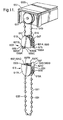
- Figures 11-12 show a seventh embodiment 601 of the control system of this invention which is similar to the control system of 501 of Figures 8-10 and for which corresponding reference numerals (greater by 100) are used for describing the same or corresponding parts.
- the control system 601 features detachable upper and lower portions 613, 615 of a housing 603.
- On a top surface 691 of a front bridging wall member 621C of the lower housing portion 615 and on a bottom surface 677 of a back bridging wall member 621 B of the upper housing portion 613 are front and back, laterally flexible but resilient, cantilever beams 683, 685, respectively.
- the cantilever beams extend vertically towards each other and, at their vertical extremities, have front and back snap-lugs 687, 689.
- the laterally outer surface 683B, 685B of each cantilever beam 683, 685 is coplanar with the outer surface of its bridging wall member 621C, 621B, respectively.
- the snap-lugs 687, 689 are generally triangular in shape and extend laterally inwardly, towards each other.
- Each snap-lug preferably has a gentle entrance ramp 687C, 689C at its vertical extremity or entrance side, a sharper angled retraction ramp 687A (not shown), 689A adjacent its beam or at its retraction side, and vertically-extending intermediate portion 687B, 689B between them.
- the upper front and lower back, side bridging wall members 621A, 621 D are in the shape of longitudinally-extending beam-like snap-lug retainers 695, 697.
- the snap-lug retainers 695, 697 are located slightly inwardly of the laterally outer edges of the left and right walls 617, 617A, 619, 619A of the housing 603.
- the retainers 695, 697 preferably have generally triangular shape with: i) a vertically-extending, laterally outer wall 695A, 697A that is slightly inwardly of the laterally outer edges of the left and right walls 617, 617A, ii) a horizontally-extending end wall 695B, 697B that forms a top surface 693 on the back lower bridging wall member 621 D or a bottom surface 675 of the front upper bridging wall member 621A, and iii) a laterally-and inwardly-extending connecting wall 695C, 697C.
- the snap-lugs 687, 689 on the cantilever beams 683, 685 are adapted for snap-fit engagement with the snap-lug retainers 695, 697 to attach the two housing portions 613, 615 together.
- the vertical distance between each snap-lug 687, 689 and the top surface 691 on the lower front bridging wall member 621 C or the bottom surface 675 of the upper back bridging wall member 621B, respectively is no more than the height of the vertically-extending outer wall 695A, 697A of one of the snap-lug retainers 695, 697, respectively.
- the entrance ramps 687C, 689C of the snap-lugs 687, 689 are urged against the end walls 695B, 697B of the retainers 695, 697, thereby forcing the snap-lugs and the cantilever beams 683, 685 laterally apart until the snap-lugs and the cantilever beams 683, 685 pass the retainers.
- the snap-lugs can engage their adjacent retainers with the laterally-inner surface 683A, 685A of their cantilever beams 683, 685 laterally adjacent the outer wall 695A, 697A of their adjacent retainers.
- the intermediate and lower drive wheels 647, 609 are operatively engaged, and during normal operation of the control system 601 and its operating cord 611, the snap-lugs 687, 689 are held in engagement with the snap-lug retainers 695, 697. If the first and second cord portions 631, 633 are pulled downwardly simultaneously by an excessive force, the snap-lugs are pulled out of engagement with the retainers, and the lower housing portion is detached from the upper housing portion.
- the cantilever beams 683, 685 will flex slightly laterally outward as a result of the force on the retraction ramps 687A, 689A of the snap-lugs, exerted by the end walls 695B, 697B of the retainers. The snap-lugs 687, 689 will then be disconnected from the retainers 695, 697.
- the lower drive wheel 609 is releasably mounted in the lower housing portion 615 to provide an extra safety feature.
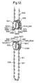
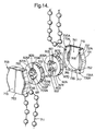
- FIGS 13-14 show an eighth embodiment 701 of the control system of this invention which is similar to the control system of 301 of Figures 5-6 and for which corresponding reference numerals (greater by 400) are used for describing the same or corresponding parts.
- the control system 701 has a housing 703, which is the main housing of the control system and holds a rotatable lower drive wheel 709 and a rotatable intermediate drive wheel 747.
- a rotatable upper drive wheel 707 is provided in a fixed auxiliary housing 751 (partly shown) connected to a head rail 705 of a venetian blind.
- An auxiliary operating cord 749 is looped about and connects the upper and intermediate drive wheels, and a main operating cord 711 is looped over the lower drive wheel 709.
- the intermediate drive wheel 747 and the lower drive wheel 709 are coaxially and releasably, preferably snap-fit, connected to each other in the main housing 703.
- the intermediate drive wheel 747 has a circular left wall 747A and right wall 747B (not visible) that are spaced apart but connected by a coaxial cylindrical bridging member 747C.
- the bridging member 747C has an outer circumferential grooved surface 747D for accommodating the auxiliary operating cord 749, and an inner annular surface 747E surrounding a central axial opening 747F.
- the lower drive wheel 709 has a circular left wall 709A and right wall 709B, a cylindrical bridging member 709C, with an outer circumferential grooved surface 709D for accommodating the operating cord 711 and an inner annular surface 709E surrounding a central axial opening 709F.
- the left wall 747A of the intermediate drive wheel 747 is coaxially and releasably, preferably snap-fit, connected to the right wall 709B of the lower drive wheel 709.
- the snap fit connection, generally 800, of the intermediate and lower drive wheel 747, 709 includes a pair of cantilever beams 801, 803, mounted on the inner annular surface 747E of the intermediate drive wheel and extending longitudinally to the left of its left wall 747A and towards the central axial opening 709F of the lower drive wheel.
- a complementary slot 809, 811 extending longitudinally in the inner annular surface 709E of the lower drive wheel between its left and right walls 709A, 709B.
- the beams 801, 803 are preferably on diametrically opposite sides of the inner annular surface 747E of the intermediate drive wheel, and the slots 809, 811 are preferably on diametrically opposite sides of the inner annular surface 709E of the lower drive wheel.
- Each beam 801, 803 is generally C-shaped, the closed end of the C-shape extending outwardly of the inner annular surface 709E of the lower drive wheel 709 and including a projecting snap-lug 805, 807 on its radially outward surface.
- Each beam is flexible but resilient, so that when the intermediate and lower drive wheels 747, 709 are pushed axially together to connect them coaxially, the beams can flex somewhat radially inwardly of the inner annular surface 747E of the intermediate drive wheel and will then flex back radially outward when the snap-lugs 805, 807 snap into one of the complementary slots 809, 811 of the inner annular surface 709E of the lower drive wheel.
- the snap-lugs 805, 807 extend radially outwardly of the closed end of the C-shaped beams and are to the left of the left wall 747A of the intermediate wheel 747.
- Each snap-lug has an entrance ramp 805A, 807A (not shown) at its left or entrance side which slopes gently to the right and radially towards the inner annular surface 747E of the intermediate wheel 747.
- At the right end of each entrance ramp 805A, 807A is a retraction ramp 805B, 807B (not shown) which slopes more sharply to the right and radially away from the inner annular surface 747E of the intermediate wheel.
- the right end of each retraction ramp 805B, 807B is adjacent the left wall 747A of the intermediate wheel 747.
- the front of each snap-lug 805, 807, to the left of its entrance ramp 805A, 807A can be sharp but is preferably truncated as shown in Figures 13 and 14.
- the beams 801, 803 are adapted to engage the complementary slots 809, 811 in the inner annular surface 709E surrounding the central axial opening 709F of the lower drive wheel 709.
- Each slot 809, 811 has an entrance surface 809A, 811A (not shown) that is somewhat radially inwardly of the lower drive wheel 709 and extends axially and to the left from its right wall 709B, a carrier surface 809B, 811B (not shown) that is more radially inward of the lower drive wheel 709 and extends axially and to the left from the entrance surface, a locking ledge 809C, 811C (not shown) that extends radially outwardly of the lower drive wheel and to the left from the carrier surface and an end surface 809D, 811 D (not shown) that is somewhat radially inwardly of the lower drive wheel 709 and extends axially and to the left to the left wall 709A of the lower drive wheel 709.
- the entrance ramps 805A, 807A of the snap-lugs 805, 807 on the beams of the intermediate wheel initially are moved axially along the entrance surfaces 809A, 811A of the slots 809, 811of the lower drive wheel.
- the beams 805,807 are thereby flexed somewhat radially inwardly of the lower drive wheel 709 and towards each other.
- the snap-lugs 805,807 engage the slots 808, 811 with their retraction ramps 805B, 807B to the right of and the locking ledges 809C, 811C of the slots.
- an additional pair of cantilever beams 801A, 803A (not shown) with radially outwardly-extending snap-lugs 805A, 807A are each mounted on the inner annular surface 709E of the lower drive wheel 709, midway between its slots 809, 811.
- the additional cantilever beams 801A, 803A are mirror images of the beams 801, 803 with snap lugs 805, 807 of Figures 13-14, and each extends longitudinally to the right of the right wall 709B of the lower drive wheel and towards the central axial opening 747F of the intermediate drive wheel 747.
- complementary longitudinally-extending slots 809A, 811A are provided in the inner annular surface 747E of the intermediate drive wheel 747, each being midway between its cantilever beams 801, 803.
- the complementary slots 809A, 811A are mirror images of the slots 809, 811 of Figures 13-14, and each extends longitudinally between the left and right walls 747A, 747B of the intermediate drive wheel.
- the two wheels 709, 747 can thus be doubly snap-fit coaxially together to keep them from rotating relative to one another.
- the main housing 703 has a left portion 715, in which is the lower drive wheel 709, and a right portion 717, in which is the intermediate drive wheel 747.
- the two housing portions are identical but inverse mirror images.
- the right housing portion 717 has a right wall 719, on the left side of which is a U-shaped semi-circumferential wall 721 with an open top.
- the U-shaped wall 721 has a back leg 735, a front leg 737 and a bottom leg 739, and each leg has a left surface 735A, 737A, 739A, respectively.
- the legs of the U-shaped wall form a semi-circular internal recess 741, in which the intermediate drive wheel 747 is rotatably held with the right surface of its right wall 747B being against the inner surface of the right wall 719 of the right housing portion and with its circumferential grooved surface 747D being closely adjacent to the radially inner surfaces of the U-shaped wall 821.
- guiding pins 743, 745 which extend to the left.
- guiding holes 748, 751 which extend to the left.
- the left housing portion 715 has a corresponding left wall 753, on the right side of which is a U-shaped semi-circumferential wall 756 with an open bottom and a semi-circular internal recess (not shown). Guiding pins and holes (not shown), which correspond to the guiding pins 743, 745 and guiding holes 748,752 of the right housing portion 717 but which extend to the right, are provided in the U-shaped wall 756.
- the operating cord 711 is looped over the lower drive wheel 709, and in normal operation, pulling either of the depending cord portions 731, 733 will result in rotation of the lower drive wheel.
- the coaxial connection between the lower and intermediate drive wheels 709, 747 ensures that once the lower drive wheel turns, so will the intermediate drive wheel. Rotation of the intermediate drive wheel 747 results in movement of the auxiliary operating cord 747 which turns the upper drive wheel 707.
- their snap-fit connection 800 will become disconnected, and thereby, the lower drive wheel and the operating cord 711 will be disconnected from the system 701.
- the upper drive wheels 7, 107, 207, 507, 607 and the lower drive wheels 9, 109, 209, 509, 609 which are gear wheels that are operatively connected by inter-engaging gear teeth, could be replaced by drive wheels that are operatively connected by friction means.
- the lower drive wheels 307, 407 and the intermediate drive wheels 347, 447 could be replaced by conventional blind drive cords without beads.
- control systems 1,101,201 cause a reversal of the rotation direction between their lower drive wheels 9, 109, 209 and upper drive wheels 7,107, 207 -- which might be confusing for a person using their operating cords 1, 11, 111 -- additional small intermediate pinion wheels could be mounted in their housings 3, 103, 203. These pinion wheels could operatively connect the lower drive wheels to the upper drive wheels, so that the lower and upper drive wheels turn in the same direction.
- one cantilever beam 683 extends vertically from the lower housing portion 615 and the other 685 from the upper housing portion 613.
- both beams could extend vertically from either the upper or lower housing portion, towards snap-lug retainers 695, 697 on the other housing portion.
Landscapes
- Engineering & Computer Science (AREA)
- Structural Engineering (AREA)
- Architecture (AREA)
- Civil Engineering (AREA)
- Blinds (AREA)
- Selective Calling Equipment (AREA)
- Ropes Or Cables (AREA)
Abstract
Description
- This invention relates generally to a control system for operating and positioning a covering for an architectural opening, such as a window blind (e.g., a horizontal or vertical venetian blind). This invention particularly relates to a control system which includes a drive wheel for positioning a blind and an endless-loop operating cord, looped over the drive wheel, so that depending portions of the cord are on opposite sides of the drive wheel. This invention quite particularly relates to a safety device for such a control system that includes means for allowing the cord to be detached from the drive wheel when a generally downward force is exerted simultaneously on both depending portions of the cord.
- Means for releasing an endless-loop operating cord, in its entirety, from a control system of a window blind to ensure the safety of children that might become entangled in the cord are described in EP 0 869 254. The operating cord of EP 0 869 254 depends from opposite sides of a drive wheel but is not looped over the drive wheel. Rather, its operating cord is slidably attached to a mounting plate, which is releasably mounted on a mounting support, and the cord is kept in operative engagement with the lower half of the drive wheel by the mounting plate. When both depending portions of the cord are pulled at the same time, the mounting plate is released from the mounting support, thereby releasing the cord from the control system, thereby preventing possible injury to a child whose head may have become entangled in the cord.
- However a drawback of the system of EP 0 869 254 is that since its operating cord is not slung over its drive wheel as is conventional, extra parts (at extra cost) must be provided to guide and maintain the cord in operative engagement with the drive wheel. These extra parts include the mounting plate, mounting support and a pair of pulleys located on the mounting plate. This system is also less energy efficient in positioning the blind, for a given effort pulling downwardly on one depending portion of the cord. Furthermore, the extra parts make failure of the control system, in routine operation of the blind, more likely.
- In accordance with this invention, a cord-operated control system for a covering for an architectural opening is provided which includes:
- a housing;
- a first drive wheel that is operatively connected to a driven blind member, adapted to rotate in opposite directions to open and close the covering; the first drive wheel being adapted to rotate in opposite directions and being connected to the driven blind member, so that the driven blind member rotates with the first drive wheel;
- a second drive wheel that is adapted to rotate in opposite directions within the housing, is rotatably connected to the housing and is operatively connected to the first drive wheel, so that the first drive wheel rotates with the second drive wheel;
- an operating cord that is an endless loop and is looped over the second drive wheel and has first and second, cord portions depending from opposite sides of the second drive wheel, whereby an axial pulling force on only the first cord portion causes the second drive wheel to rotate in a first direction and an axial pulling force on only the second cord portion causes the second drive wheel to rotate in an opposite second direction; and
- release means for disconnecting, preferably non-destructively disconnecting, the second drive wheel from the first drive wheel only when there is an axial pulling force on both the first and second cord portions simultaneously.
- In a further advantageous embodiment, the second drive wheel is operatively connected to the first drive wheel by a third drive wheel and an auxiliary operating cord. Advantageously, both the second drive wheel and the third drive wheel are rotatably mounted in the housing, the auxiliary drive cord is an endless loop and is looped over the first drive wheel and the third drive wheel to operatively connect them, and wherein, when the second drive wheel is rotated, it causes the third drive wheel to rotate, which in turn causes the auxiliary operating cord to drive the first drive wheel to rotate and thus causes the driven member to rotate.
- In a still further advantageous embodiment, the release means are for disconnecting a lower portion of the housing with a drive wheel from an upper portion of the housing with another drive wheel. Advantageously, the release means comprises a releasable snap engagement arrangement between the lower and upper housing portions.
- In a yet further advantageous embodiment, the second and third drive wheels are coaxially connected, and the release means are for disconnecting the coaxially-connected, second and third drive wheels. Advantageously, the release means comprises a releasable snap fit arrangement between the second and third drive wheels.
- Further aspects of the invention will be apparent from the detailed description below of particular embodiments and the drawings thereof, in which:
- Figure 1 is a perspective view of a first embodiment of the control system of this invention in its housing on a head rail of a venetian blind;
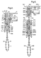
- Figure 2 is a sectional view of the first embodiment of the control system, taken along a longitudinally-extending plane through the housing as shown in Figure 1; a lower drive wheel (not in section) in the housing, with an operating cord looped (not in section) about it, is engaged with an upper drive wheel (not in section) in the housing and thereby with the rest of the system;
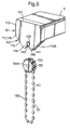
- Figure 3 is a perspective view, similar to Figure 1, of a second embodiment of the control system of this invention in its housing on a head rail of a venetian blind; a drive wheel of the control system, with an operating cord looped about it, has been disconnected from the rest of the system;
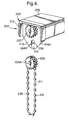
- Figure 4 is a perspective view, similar to Figure 1, of a third embodiment of the control system of this invention in its housing (partially cut-away along a laterally-extending plane) on a head rail of a venetian blind; a lower drive wheel of the control system, with an operating cord looped about it, has been disconnected from the rest of the system;
- Figure 5 is a perspective view of a fourth embodiment of the control system of this invention in its housing (exploded) and in its auxiliary housing (partially cut-away along a laterally-extending plane) on a head rail of a venetian blind; a lower drive wheel in the housing, with an operating cord looped about it, is engaged with an intermediate drive wheel in the housing, and the intermediate drive wheel has an auxiliary operating cord looped about it and about an upper drive wheel in the auxiliary housing, so that the lower drive wheel engages the rest of the system;
- Figure 6 is a sectional view of the fourth embodiment of the control system, taken along a longitudinally-extending plane through its housing and its auxiliary housing as shown in Figure 5; the lower drive wheel, operating cord, auxiliary drive wheel, auxiliary operating cord and upper drive wheel are not in section;
- Figure 7 is a perspective view of a portion of a fifth embodiment of a control system of this invention that is very similar to the control system of Figures 5 and 6; a lower drive wheel in its housing (exploded), with an operating cord looped about it, engages an intermediate drive wheel in the housing, and the intermediate drive wheel has an auxiliary operating cord looped about it and about an upper drive wheel in its auxiliary housing, so that the lower drive wheel engages the upper drive wheel;
- Figure 8 is a perspective view, of a sixth embodiment of the control system of this invention in its housing on a head rail of a venetian blind, with a lower portion of the housing disconnected from an upper portion;
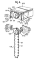
- Figure 9 is a perspective view, similar to Figure 8, of the sixth embodiment of the control system with the lower and upper portions of its housing (partially cut-away along a laterally-extending plane) disconnected;
- Figure 10 is a perspective view, similar to Figures 8 and 9, of the sixth embodiment of the control system with the lower and upper portions of its housing (partially cut-away along a laterally-extending plane) connected;
- Figure 11 is a perspective view of a seventh embodiment of the control system of this invention in its housing and in its auxiliary housing (partially cut-away along a laterally-extending plane) on a head rail of a venetian blind, with a lower portion of the housing disconnected from an upper portion;
- Figure 12 is a perspective view, similar to Figure 11, of the seventh embodiment of the control system with the lower and upper portions of its housing (partially cut-away along a laterally-extending plane) disconnected;
- Figure 13 is a perspective view of an eighth embodiment of the control system of this invention in its housing (exploded) and in its auxiliary housing (partially cut-away along a laterally-extending plane) on a head rail of a venetian blind; a left drive wheel in a left portion of its housing, with an operating cord looped about it, engages a right intermediate drive wheel in a right portion of the housing, and the right drive wheel has an auxiliary operating cord looped about it and about an upper drive wheel in its auxiliary housing, so that the left drive wheel engages the upper drive wheel; and
- Figure 14 is a perspective view, similar to Figure 13, of the eighth embodiment of the control system with the left and right, drive wheels disconnected in the housing (exploded).
- Figures 1 and 2 show a
control system 1 of this invention in ahousing 3, mounted as an end cap on a longitudinally-extendinghead rail 5 of a venetian blind (not shown). Thecontrol system 1 includes a first orupper drive wheel 7, a second orlower drive wheel 9 and a conventional closed loop or endless-loop,operating cord 11, such as a bead chain, which functions as an operating element of the blind. Theupper drive wheel 7 is operatively connected to a conventional, longitudinally-extending, drivenmember 5A, rotation of which causes movement of the blind, such as a traversing, lifting and/or tilting movement of the blind slats. For example, the drivenmember 5A can be a conventional drive shaft of a roller blind, central control shaft for a roman shade, lift or tilt shaft of a horizontal venetian blind or tilt shaft of a vertical venetian blind. Looped about thesecond drive wheel 9 is theoperating cord 11. - The
housing 3, which accommodates the upper and lower, drivewheels first housing portion 13 and a lower orsecond housing portion 15. Theupper housing portion 13 comprises an upstanding, laterally-extending, upper left (as shown in Figures 1-2)wall portion 17, remote from thehead rail 5, and an upstanding, laterally-extending, upper right (as shown in Figures 1-2)wall portion 19, adjacent thehead rail 5. Theupper wall portions bridging wall member 21, atop theupper wall portions bridging wall members upper wall portions upper space 23 between theupper wall portions upper drive wheel 7. Theupper housing portion 13 and thehead rail 5 preferably have the same profile when viewed from a longitudinal end of the head rail. Thelower housing portion 15 likewise comprises an upstanding, laterally-extending, lowerleft wall portion 17A and an upstanding, laterally-extending, lowerright wall portion 19A. Thelower wall portions upper wall portions wall bridging member 21 and the front and back,bridging wall members lower space 23A is defined between thelower wall portions upper space 23. Thelower space 23A accommodates thelower drive wheel 9 and the upper portions of theoperating cord 11, passing laterally over the lower drive wheel. Preferably the laterally-extending width of each of the lower, left and right,wall portions right wall portions left wall portions right wall portions - The upper and
lower drive wheels housing 3 in a generally conventional manner, as described, for example, in US 6,158,563 or US 4,372,432. In this regard, mounting journals or stub axles on opposite sides of thedrive wheels lower wall portions - As shown in Figure 2, it is preferred that the
upper drive wheel 7 be rotatably mounted as follows in theupper housing portion 13. The inner surface of the upperleft wall portion 17 has a longitudinally-extending upper left bearing 24, in which is positioned a corresponding coaxial upperleft journal 25, located at the center of the left side of theupper drive wheel 7. Extending longitudinally through the upperright wall portion 19 is an upper right bearing 26, which is coaxial with the upper left bearing 24, and extending longitudinally through the left side of thehead rail 5 is abearing 27 that is adjacent to, and coaxial, with the upper right bearing 26 and the drivenmember 5A. Positioned in theadjacent bearings right journal 28. The upperright journal 28 is located at the center of the right side of theupper drive wheel 7 and is connected to the drivenmember 5A, so that the upper drive wheel and the driven member are operatively connected to rotate together. - As also shown in Figure 2, it is also preferred that the
lower drive wheel 9 be rotatably mounted in thelower housing portion 15. The inner surfaces of the lower, left andright wall portions lower bearings 24A, in each of which is positioned one of a pair of corresponding coaxiallower journals 25A, located at the center of the left and right sides of thelower drive wheel 9. - The
upper drive wheel 7 is operatively connected to thelower drive wheel 9, so that rotation of thelower drive wheel 9 causes rotation of theupper drive wheel 7. Preferably, the circumference of each of thedrive wheels gear teeth gear teeth 29 of theupper drive wheel 7 interact with thegear teeth 29A of thelower drive wheel 9, so that the twodrive wheels - The
lower drive wheel 9 is adapted to accommodate theoperating cord 11 which is looped about and engages the circumference of the lower drive wheel. In this regard, thelower drive wheel 9 can be a simple pulley for a cord or have an exterior rim that is specially shaped with acircumferential groove 30 to receive theoperating cord 11. Theoperating cord 11 has two dependingportions lower drive wheel 9. - In accordance with this invention, the
lower drive wheel 9 is releasably mounted in thelower housing portion 15. In this regard, it is preferred that eachlower bearing 24A preferably has a beveled edge or rim and/or that each correspondinglower journal 25A has a beveled edge. Additionally, the left andright walls wall portions housing 3 are relatively flexible and resilient. This relative flexibility and resilience are a function of the lack of bridging wall members between thelower wall portions lower wall portions - The
lower drive wheel 9 is normally held in place in thehousing 3 -- so that the lower drive wheel is operatively connected to theupper drive wheel 7 and thereby to the rest of thecontrol system 1 -- by the lower, left and right,wall portions housing 3 and by the engagement of thelower journals 25A with thelower bearings 24A. Indeed, when thelower drive wheel 9 is mounted in thecontrol system 1 by pushing thelower drive wheel 9 upwardly between the flexible, lower, left and right,wall portions lower bearings 24A, thelower journals 25A force the lower, left and right,wall portions lower wall portions lower drive wheel 9 rotatably in thelower space 23A and operatively connected to theupper drive wheel 7 and, thereby, to the drivingmember 5A. - Preferably, the longitudinal width of the
lower drive wheel 9 at its widest portion, including the beveledlower journals 25A, is slightly larger than the largest width of thelower space 23A of thelower housing portion 15. The largest width of thelower space 23A is preferably where thelower bearings 24A are located because this width includes the longitudinal depth of the lower bearings. Nevertheless, the largest width of thelower space 23A is still smaller than the widest part of thelower drive wheel 9 where thelower journals 25A are located. Thereby, after thelower journals 25A of thelower drive wheel 9 snap into thelower bearings 24A of the lower housing portion 15 (when the lower drive wheel is pushed between the flexible,lower wall portions lower housing portion 15 during normal operation of theoperating cord 11 when there is an axial pulling force downwardly on only its first orsecond cord portion - However if both the first and
second cord portions operating cord 11 -- the downward force on the operating cord produces a longitudinally outwardly-directed force acting through the beveled edges of bothlower journals 25A bearing downwardly on the beveled rims of thelower bearings 24A. This longitudinally outwardly-directed force will cause the flexible, lower, left and right,wall portions housing 3 to be pushed longitudinally apart from each other, and the lower wall portions may also be slightly bent temporarily by such force but without permanent bend lines forming in the lower wall portions. As thelower wall portions lower journals 25A will slide downwardly out of theirlower bearings 24A. Continued downward pulling on both the first andsecond cord portions lower drive wheel 9, together with theoperating cord 11, downwardly and out from between thewalls housing 3, thereby disconnecting, thelower drive wheel 9 and the operating cord from theupper drive wheel 7 and hence from the rest of thecontrol system 1. - After the
lower drive wheel 9, with theoperating cord 11, has been disengaged from theupper drive wheel 7 by a downward force on both the first andsecond cord portions housing 3 and operatively reconnected to the upper drive wheel and the rest of thecontrol system 1. This can be done simply by pushing thelower drive wheel 9 with theoperating cord 11 upwardly into thelower housing portion 15, so that itslower journals 25A are again in thelower bearings 24A. In this regard, pushing thelower journals 25A back into thelower bearings 24A is easier if the lower journals or the lower bearings or both have beveled edges. - In accordance with this invention, the design and construction of the elements of the
control system 1 can be varied to vary the required amount of downward force, applied simultaneously to the first andsecond cord portions lower drive wheel 9 from theupper drive wheel 7. For example, the angle of the beveled edges of thelower journals 25A, the angle of the beveled edges of thelower bearings 24A, the shape and dimensions of the lower journals and lower bearings and/or the relative flexibility and resilience of the left and right,wall portions housing 3 can affect the amount of downward force on the first andsecond cord portions lower drive wheel 9 from engagement with theupper drive wheel 7. In this regard, the more rigid thelower wall portions lower drive wheel 9. Also if both the edges of thelower bearings 24A and thelower journals 25A are beveled at a greater angle (relative to horizontal), less force is likely to be required to release thelower drive wheel 9. Likewise if both thelower bearings 24A and thelower journals 25A are longitudinally longer, it will be more difficult to release thelower drive wheel 9. Also, the thickness, as well as the choice of materials, of thehousing 3, particularly itslower wall portions - If desired, conventional clutches and/or brakes for regulating the rotation of the driven
member 5A, in response to rotation of theupper drive wheel 7 or the weight of the blind, can be provided in thehead rail 5. These can be of the type disclosed by, for example, US 4,372,432 and US 6,158,563. - Figure 3 shows a
second embodiment 101 of a control system of this invention which is similar to thecontrol system 1 of Figures 1 and 2 and for which corresponding reference numerals (greater by 100) are used below for describing the same or corresponding parts. - The
control system 101 is in ahousing 103, mounted as an end cap on a head rail 105 of a venetian blind (not shown). Thecontrol system 101 includes: an upper drive wheel (not shown), rotatably mounted in anupper portion 113 of thehousing 103 and operatively connected to a driven member (not shown); alower drive wheel 109, rotatably connected to alower portion 115 of thehousing 103 and operatively connected to the upper drive wheel; and an endless-loop, operating cord 111, looped over the lower drive wheel. - The inner surfaces of the lower, left and right,
wall portions 117A,119A of thelower housing portion 115 each have a lower journal bore or bearing 124A that extends longitudinally completely through the wall portion and is complementary to a corresponding, longitudinally-extending, lower journal orstub axle 125A on each of the left and right sides of thelower drive wheel 109. To make thelower drive wheel 109 releasably mounted in thelower housing portion 115, each lower journal bore 124A has a keyhole shape that is open at the bottom of itslower wall portion 117A, 119A. In this regard, each keyhole-shaped lower bearing 124A has an upper, generallycircular portion 139 that has a diameter greater than eachlower journal 125A and a lower, downwardly-extending,stem portion 141 that is open at the bottom. Thecircular portion 139 of each lower bearing 124A is adapted to hold one of thelower journals 125A of thelower drive wheel 109 during normal operation of thecontrol system 101. The lateral sides of thestem portion 141 of each lower bearing 124A diverge laterally and downwardly from beneath the upper,circular portion 139 where the lateral sides are relatively close and form arestricted opening 143 in itslower wall portion 117A,119A at the upper end of the stem portion. The lateral width of this restrictedopening 143 is preferably less than the diameter of eachjournal 125A. The diverging sides of eachtapered stem portion 141 of a lower bearing 124A form twofingers 145 on laterally-opposite sides of the of the lower bearing. In accordance with this invention, the lower, left and right,wall portions 117A, 119A, particularly thefingers 145, are relatively flexible and resilient. - In order to better hold the
lower journals 125A of thelower drive wheel 109 in thecircular portions 139 of the lower bearings 124A, each lower journal preferably has a circumferential groove (not shown) near its longitudinal end. The groove of each lower journal engages longitudinally the left and right sides of the adjacentlower wall portion 117A, 119A, about the circular portion of the lower bearing, in which the lower journal is held, and thereby prevents undesired longitudinal slippage of the lower drive wheel. - A downward pulling force simultaneously on both the first and second depending
portions lower journals 125A of thelower drive wheel 109 downwardly, out of thecircular portions 139 of the lower bearings 124A through their restrictedopenings 143, then through theirstem portions 141 and finally out the bottom of the stem portions. In this regard, the two flexible andresilient fingers 145 on eachlower wall portion 117A, 119A will be pushed laterally apart in order to allow thelower journals 125A to move downwardly, past the restrictedopenings 143, and thefingers 145 may also be slightly bent temporarily by such downward movement of the lower journals but without permanent bend lines forming in the lower wall portions. This will disconnect thelower drive wheel 109, together with the operating cord 111, from the upper drive wheel (not shown) and from the rest of thecontrol system 101. However under normal operating conditions, thelower journals 125A will be held in thecircular portions 139 of the lower bearings 124A of thelower housing portion 115. Indeed, the twofingers 145 will not move apart and allow thelower journals 125A to move downwardly past the restrictedopenings 143 in the lower bearings 124A unless the downward force on both the first andsecond cord portions - The
lower drive wheel 109, with the operating cord 111, can be pushed back into thehousing 103 and operatively reconnected to the upper drive wheel (not shown) and the rest of thecontrol system 101. This can be done simply by pushing thelower drive wheel 109 with the operating cord upwardly into thelower housing portion 115, past the twofingers 145 and the restrictedopenings 143, so that itslower journals 125A are again in thecircular portions 139 of the lower bearings 124A. - Figure 4 shows a
third embodiment 201 of a control system of this invention which is similar to thecontrol system 101 of Figure 3 and for which corresponding reference numerals (greater by 100) are used below for describing the same or corresponding parts. - The
control system 201 is in ahousing 203, mounted as an end cap on ahead rail 205 of a venetian blind (not shown). Thecontrol system 201 includes: anupper drive wheel 207, rotatably mounted in anupper portion 213 of thehousing 203 and operatively connected to a driven member (not shown); alower drive wheel 209, rotatably connected to alower portion 215 of thehousing 203 and operatively connected to the upper drive wheel; and an endless-loop,operating cord 211, looped over the lower drive wheel. - The inner surfaces of the left and right, lower wall portions 217A (not shown), 219A of the
lower housing portion 215 each have a longitudinally-extendinglower bearing 224A that is complementary to a corresponding longitudinally-extending lower journal 225A, located at the center of the each side of thelower drive wheel 209. Eachlower bearing 224A is formed as a blind recess with a longitudinally-extending, upper, generallycircular hole 239 and a downwardly-extending stem portion or groove 241, connected to the circular hole. Thecircular hole 239 of eachlower bearing 224A is deeper than itsstem portion 241, in that itscircular hole 239 extends longitudinally farther from the inner surface of its lower wall portion 217A (not shown), 219A than does itsstem portion 241. Preferably the lower journals 225A or thelower bearings 224A, especially both, have beveled edges. - The portions of the
circular holes 239 of thelower bearings 224A, extending longitudinally further and thus deeper than thestem portions 241 of the lower bearings, are adapted to accommodate and hold the lower journals 225A of thelower drive wheel 209 in thehousing 203 during normal operation of thecontrol system 201. When excessive downward force is exerted simultaneously on both dependingportions operating cord 211, the beveled edges of the lower journals 225A bear down on the beveled edges of thecircular holes 239 of thelower bearings 224A . This causes the flexible, lower, left and right, wall portions 217A (not shown), 219A of thehousing 203 to be pushed longitudinally apart from each other and possibly the lower wall portions also to be slightly bent temporarily but without permanent bend lines forming in the lower wall portions. As a result, the lower journals 225A of thelower drive wheel 209 are dislodged from thecircular holes 239 of thelower bearings 224A and then pulled downwardly in theirstem portions 241 until the lower journals are pulled downwardly out of the bottom of thehousing 103. This will disconnect thelower drive wheel 209, together with theoperating cord 211, from theupper drive wheel 207 and from the rest of thecontrol system 201. - The
lower drive wheel 209, with theoperating cord 211, can be pushed back into thehousing 203 and operatively reconnected to theupper drive wheel 207 and the rest of thecontrol system 201. This can be done simply by pushing thelower drive wheel 209 with the operating cord upwardly into thelower housing portion 215, along thestem portions 241 of thelower bearings 224A, so that its lower journals 225A are again in thecircular portions 239 of the lower bearings. - Figures 5 and 6 show a
fourth embodiment 301 of the control system of this invention which is similar to the control system of 201 of Figure 4 and for which corresponding reference numerals (greater by 100) are used for describing the same or corresponding parts. - The
control system 301 features a third orintermediate drive wheel 347 and a second orauxiliary drive cord 349. Thehousing 303, which is the main housing of thecontrol system 301, holds a rotatablelower drive wheel 309 and the rotatableintermediate drive wheel 347. A rotatableupper drive wheel 307 is provided in a fixedauxiliary housing 351 connected to ahead rail 305 of a venetian blind. - As shown in Figure 6, the
auxiliary housing 351 has an upstanding, laterally-extending, leftwall 353, remote from thehead rail 305, and an opposite upstanding laterally-extending,right wall 355, adjacent to or integral with the head rail. The left andright walls top wall member 357, atop the left and right walls, and by a pair of upstanding front and back, side bridgingwall members upper drive wheel 307 has left and right,upper journals upper bearing 324 in theleft wall 353 of theauxiliary housing 351 and a rightupper bearing 328 in theright wall 355 of the auxiliary housing. - The
main housing 303, carrying thelower drive wheel 309, is attached to theupper drive wheel 307 by an endless-loopauxiliary drive cord 349 that is looped about and engages the circumference of both theintermediate drive wheel 347 and theupper drive wheel 307. Thehousing 303 can thus be easily retrofitted to an existing blind with anupper drive wheel 307. Themain housing 303 has anupper portion 313, in which theintermediate drive wheel 347 is mounted, and alower portion 315, in which thelower drive wheel 309 is mounted. Thelower drive wheel 309 is operatively connected to theupper drive wheel 307 by means of theintermediate drive wheel 347 and theauxiliary drive cord 349, so that rotation of thelower drive wheel 309 causes rotation of the intermediate drive wheel, which in turn causes rotation of the upper drive wheel. Thelower drive wheel 309 can be rotated by pulling either one of the dependingportions main drive cord 311 that is looped over it. - As also shown in Figure 6, the
upper portion 313 of thehousing 303 includes a pair of opposite, upstanding, laterally-extending, left and right,upper wall portions lower portion 315 of thehousing 303 includes a pair of opposite, upstanding, laterally-extending, left and right,lower wall portions lower 319A extending downward from thewall portions 317Aupper wall portions opposite wall portions wall members 321A, 321B. The side bridging wall members extend longitudinally between the opposite wall portions. As shown in Figure 5, the side bridging wall members can be relatively short, leaving unconnected large portions of the front and back of the upper andlower housing portions - The inner surfaces of the
lower wall portions 317A (not shown), 319A of themain housing 303 each have a longitudinally-extendinglower bearing 324A that is complementary to, and carries, a corresponding longitudinally-extendinglower journal 325A protruding from left and right sides of thelower drive wheel 309. Eachlower bearing 324A is formed as a circularblind hole 339. Preferably, thelower journals 325A or thelower bearings 324A, or both have beveled edges. Theblind holes 339 of thelower bearings 324A are adapted to accommodate and hold thelower journals 325A of thelower drive wheel 309 in thelower portion 315 of thehousing 303 during normal operation of thecontrol system 301. - Protruding from left and right sides of the
intermediate drive wheel 347 are longitudinally-extendingintermediate journals 363 that are complementary to and carried by, longitudinally-extendingintermediate bearings 365 in the inner surfaces of theupper wall portions main housing 303. Theintermediate bearings 365 are adapted to accommodate and hold theintermediate journals 325A of theintermediate drive wheel 347 in theupper portion 313 of thehousing 303. - When excessive downward force is exerted simultaneously on both depending
portions operating cord 311, the beveled edges of thelower journals 325A bear down on the preferably also beveled edges of thecircular holes 339 of thelower bearings 324A. This causes the flexible, left and right,lower wall portions 317A (not shown), 319A of thelower portion 315 of thehousing 303 to be pushed longitudinally apart from each other and possibly to slightly bend temporarily the lower wall portions but without permanent bend lines being formed in the lower wall portions. As a result, thelower journals 325A of thelower drive wheel 309 are dislodged from theblind holes 339 of thelower bearing 324A and then pulled downwardly out of the bottom of thehousing 303. This disconnects thelower drive wheel 309, together with theoperating cord 311, from theintermediate drive wheel 347 and thus from the rest of thecontrol system 301. - Figure 7 shows a
fifth embodiment 401 of a control system of this invention which is similar to the control system of 301 of Figures 5 and 6 and for which corresponding reference numerals (greater by 100) are used for describing the same or corresponding parts. - The
control system 401 includes amain housing 403 with anintermediate drive wheel 447, a detachablelower drive wheel 409, and anauxiliary drive cord 449. An upper drive wheel (not shown), connected to a driven member (not shown) in the head rail of a venetian blind, is located in an auxiliary housing (not shown) mounted as an end cap on the head rail, above thehousing 403. Theauxiliary drive cord 449 is looped about theintermediate drive wheel 447 and the upper drive wheel, and anoperating cord 411 is looped about thelower drive wheel 409. - In the systems of Figures 1-6, the direction of rotation of the lower drive wheel and the direction of rotation of the upper drive wheel are opposite. This change in the direction of rotation can cause some confusion or irritation for the user of a venetian blind. In order to avoid this inconvenience, a pair of small parallel
intermediate pinion wheels housing 403 between thelower drive wheel 409 and theintermediate drive wheel 447. Thepinion wheels portions operating cord 411 is pulled downwardly, the upper drive wheel 407 (not shown) will rotate in the same direction as the lower drive wheel. However, when excessive downward force is exerted simultaneously on both dependingcord portions lower journals 425A of thelower drive wheel 409 bear down on beveled edges of thelower bearings 424A in inner surfaces of lower wall portions 417A (not shown), 419A of thehousing 403, so that the lower journals are dislodged from the lower bearings and the lower drive wheel is pulled downwardly out of the bottom of thehousing 403 to disconnect the lower drive wheel, together with theoperating cord 411, from theintermediate drive wheel 447 and thus from the rest of thecontrol system 401. - Preferably, the bridging
wall members housing 403 are provided with an inwardly facing contour which allows thepinion wheels housing 403. The height of thehousing 403 is preferably somewhat greater than that of thecorresponding housing 303 of thecontrol system 301 of Figures 5 and 6 in order to accommodate the pinion wheels. - Figures 8-10 shows a
sixth embodiment 501 of the control system of this invention which is similar to thecontrol system 101 of Figure 1 and for which corresponding reference numerals (greater by 500) are used for describing the same or corresponding parts. - Upper and
lower drive wheels lower portions housing 503 and are operatively engaged to each other. Theupper housing portion 513 is attached to blindhead rail 505, and thelower housing portion 515 is releasably attached to the upper housing portion, preferably by a releasable snap engagement, as described below. - As seen from Figure 9, the
upper housing portion 513 has upstanding, front and back, bridgingwall members back slots bottom surfaces bottom surfaces slots bridging wall members intermediate surfaces portions slots ledge intermediate portion 571 B, 573B, and above which is an inwardly-extendinggentle ramp - As also seen from Figure 9, the
lower housing portion 515 has upstanding, front and back, bridgingwall members top surfaces bridging wall members cantilever beams lug lower housing portions lugs slots bridging wall members upper housing portion 513. The snap-lugs gentle entrance ramp angled retraction ramp intermediate portion housing portions lugs wall members wall members slots lug portion intermediate slot portion 571 B, 573B in theupper housing portion 513 when the upper and lower housing portions are attached to each other as shown in Figure 10, but both such intermediate slot portions and snap-lug portions can be dispensed with if the snap-lugs - Preferably, the bottom surfaces 575, 577 of the bridging
wall members upper housing portion 513 contact thetop surfaces wall members lower housing 515 when the two housing portions are attached to each other. The upper housing bottom surfaces 575, 577 and the lower housing top surfaces 591, 593 are preferably horizontally-extending surfaces, and the cantilever beams 583, 585 preferably are located directly laterally inward from these surfaces, so that the upstanding laterally-outward portions of the cantilever beams, between the snap-lugs ledges inner surface portions bridging wall members - After the snap-
lugs lower housing portion 515 have been snapped into theslots wall members upper housing portion 513 , the upper and lower housing portions are securely attached to each other, and the upper andlower drive wheels - During normal use of the
operating cord 511 of thecontrol system 501, the snap-lugs slots portions operating cord 511, thelower housing portion 515 will be pulled downwardly, causing the retraction ramps 587A, 589A on its snap-lugs sloped ledges slots bridging wall members lug ramps slot ledges slots lower housing portion 515 will be detached from theupper housing portion 513, and thelower drive wheel 509 will be disengaged from theupper drive wheel 507. In this regard, the combination of the flexibility of the cantilever beams 583, 585 and the angles of the snap-lug entrance ramps 587A, 589A and the complementary slopedslot ledges - If desired, the rotatable
lower drive wheel 509 can be releasably mounted in thelower housing portion 515 as described above for thelower drive wheels control systems lower housing portion 515 is not detached from theupper housing portion 513 when both dependingportions operating cord 511 are pulled simultaneously with excessive force, thelower drive wheel 509 will still be pulled from thehousing 503. - Figures 11-12 show a seventh embodiment 601 of the control system of this invention which is similar to the control system of 501 of Figures 8-10 and for which corresponding reference numerals (greater by 100) are used for describing the same or corresponding parts.
- The control system 601 features detachable upper and
lower portions housing 603. On atop surface 691 of a frontbridging wall member 621C of thelower housing portion 615 and on a bottom surface 677 of a back bridgingwall member 621 B of theupper housing portion 613 are front and back, laterally flexible but resilient, cantilever beams 683, 685, respectively. The cantilever beams extend vertically towards each other and, at their vertical extremities, have front and back snap-lugs cantilever beam 683, 685 is coplanar with the outer surface of itsbridging wall member lugs gentle entrance ramp angled retraction ramp 687A (not shown), 689A adjacent its beam or at its retraction side, and vertically-extendingintermediate portion - The upper front and lower back, side bridging
wall members 621A, 621 D are in the shape of longitudinally-extending beam-like snap-lug retainers 695, 697. The snap-lug retainers 695, 697 are located slightly inwardly of the laterally outer edges of the left andright walls housing 603. Theretainers 695, 697 preferably have generally triangular shape with: i) a vertically-extending, laterallyouter wall 695A, 697A that is slightly inwardly of the laterally outer edges of the left andright walls end wall top surface 693 on the back lower bridging wall member 621 D or abottom surface 675 of the front upperbridging wall member 621A, and iii) a laterally-and inwardly-extending connecting wall 695C, 697C. - The snap-
lugs lug retainers 695, 697 to attach the twohousing portions lug top surface 691 on the lower front bridgingwall member 621 C or thebottom surface 675 of the upper back bridgingwall member 621B, respectively, is no more than the height of the vertically-extendingouter wall 695A, 697A of one of the snap-lug retainers 695, 697, respectively. Thereby, when the twohousing portions lugs end walls retainers 695, 697, thereby forcing the snap-lugs and the cantilever beams 683, 685 laterally apart until the snap-lugs and the cantilever beams 683, 685 pass the retainers. Then, the snap-lugs can engage their adjacent retainers with the laterally-inner surface 683A, 685A of theircantilever beams 683, 685 laterally adjacent theouter wall 695A, 697A of their adjacent retainers. - With the upper and
lower housing portions lower drive wheels operating cord 611, the snap-lugs lug retainers 695, 697. If the first andsecond cord portions end walls lugs retainers 695, 697. - Preferably, the
lower drive wheel 609 is releasably mounted in thelower housing portion 615 to provide an extra safety feature. - Figures 13-14 show an
eighth embodiment 701 of the control system of this invention which is similar to the control system of 301 of Figures 5-6 and for which corresponding reference numerals (greater by 400) are used for describing the same or corresponding parts. - The
control system 701 has ahousing 703, which is the main housing of the control system and holds a rotatablelower drive wheel 709 and a rotatableintermediate drive wheel 747. A rotatableupper drive wheel 707 is provided in a fixed auxiliary housing 751 (partly shown) connected to ahead rail 705 of a venetian blind. Anauxiliary operating cord 749 is looped about and connects the upper and intermediate drive wheels, and amain operating cord 711 is looped over thelower drive wheel 709. - The
intermediate drive wheel 747 and thelower drive wheel 709 are coaxially and releasably, preferably snap-fit, connected to each other in themain housing 703. Theintermediate drive wheel 747 has a circularleft wall 747A andright wall 747B (not visible) that are spaced apart but connected by a coaxialcylindrical bridging member 747C. The bridgingmember 747C has an outer circumferentialgrooved surface 747D for accommodating theauxiliary operating cord 749, and an innerannular surface 747E surrounding a centralaxial opening 747F. Likewise, thelower drive wheel 709 has a circularleft wall 709A andright wall 709B, acylindrical bridging member 709C, with an outer circumferentialgrooved surface 709D for accommodating theoperating cord 711 and an innerannular surface 709E surrounding a centralaxial opening 709F. Theleft wall 747A of theintermediate drive wheel 747 is coaxially and releasably, preferably snap-fit, connected to theright wall 709B of thelower drive wheel 709. - The snap fit connection, generally 800, of the intermediate and
lower drive wheel cantilever beams annular surface 747E of the intermediate drive wheel and extending longitudinally to the left of itsleft wall 747A and towards the centralaxial opening 709F of the lower drive wheel. For eachbeam intermediate drive wheel 747, there is acomplementary slot annular surface 709E of the lower drive wheel between its left andright walls beams annular surface 747E of the intermediate drive wheel, and theslots annular surface 709E of the lower drive wheel. - Each
beam annular surface 709E of thelower drive wheel 709 and including a projecting snap-lug lower drive wheels annular surface 747E of the intermediate drive wheel and will then flex back radially outward when the snap-lugs complementary slots annular surface 709E of the lower drive wheel. The snap-lugs left wall 747A of theintermediate wheel 747. Each snap-lug has anentrance ramp 805A, 807A (not shown) at its left or entrance side which slopes gently to the right and radially towards the innerannular surface 747E of theintermediate wheel 747. At the right end of eachentrance ramp 805A, 807A is a retraction ramp 805B, 807B (not shown) which slopes more sharply to the right and radially away from the innerannular surface 747E of the intermediate wheel. The right end of each retraction ramp 805B, 807B is adjacent theleft wall 747A of theintermediate wheel 747. The front of each snap-lug entrance ramp 805A, 807A, can be sharp but is preferably truncated as shown in Figures 13 and 14. - The
beams complementary slots annular surface 709E surrounding the centralaxial opening 709F of thelower drive wheel 709. Eachslot entrance surface 809A, 811A (not shown) that is somewhat radially inwardly of thelower drive wheel 709 and extends axially and to the left from itsright wall 709B, a carrier surface 809B, 811B (not shown) that is more radially inward of thelower drive wheel 709 and extends axially and to the left from the entrance surface, a locking ledge 809C, 811C (not shown) that extends radially outwardly of the lower drive wheel and to the left from the carrier surface and an end surface 809D, 811 D (not shown) that is somewhat radially inwardly of thelower drive wheel 709 and extends axially and to the left to theleft wall 709A of thelower drive wheel 709. - When the lower and
intermediate drive wheels lugs slots 809, 811of the lower drive wheel. The beams 805,807 are thereby flexed somewhat radially inwardly of thelower drive wheel 709 and towards each other. When the entrance ramps 805A, 807A of the snap-lugs have passed the entrance ramps 809A, 811A of the slots, they move axially along the carrier surfaces 809B, 811B and somewhat radially outwardly of the lower drive wheel, away from each other. Thereby, the snap-lugs 805,807 engage theslots 808, 811 with their retraction ramps 805B, 807B to the right of and the locking ledges 809C, 811C of the slots. - Preferably, an additional pair of
cantilever beams 801A, 803A (not shown) with radially outwardly-extending snap-lugs 805A, 807A are each mounted on the innerannular surface 709E of thelower drive wheel 709, midway between itsslots additional cantilever beams 801A, 803A are mirror images of thebeams right wall 709B of the lower drive wheel and towards the centralaxial opening 747F of theintermediate drive wheel 747. It is also preferred that complementary longitudinally-extendingslots 809A, 811A are provided in the innerannular surface 747E of theintermediate drive wheel 747, each being midway between itscantilever beams complementary slots 809A, 811A are mirror images of theslots right walls wheels - As also shown in figures 13,14, the
main housing 703 has aleft portion 715, in which is thelower drive wheel 709, and aright portion 717, in which is theintermediate drive wheel 747. The two housing portions are identical but inverse mirror images. - The
right housing portion 717 has aright wall 719, on the left side of which is a U-shapedsemi-circumferential wall 721 with an open top. TheU-shaped wall 721 has aback leg 735, afront leg 737 and abottom leg 739, and each leg has aleft surface intermediate drive wheel 747 is rotatably held with the right surface of itsright wall 747B being against the inner surface of theright wall 719 of the right housing portion and with its circumferentialgrooved surface 747D being closely adjacent to the radially inner surfaces of the U-shaped wall 821. On theleft surface 735A of theback leg 735A are upper and lower, guidingpins left surface 737A of thefront leg 737 are upper and lower, guidingholes - The
left housing portion 715 has a correspondingleft wall 753, on the right side of which is a U-shapedsemi-circumferential wall 756 with an open bottom and a semi-circular internal recess (not shown). Guiding pins and holes (not shown), which correspond to the guiding pins 743, 745 and guiding holes 748,752 of theright housing portion 717 but which extend to the right, are provided in theU-shaped wall 756. When the coaxially connected lower andintermediate wheels respective housing portions housing 703. The open top and bottom of theU-shaped walls housing portions auxiliary operating cord 749 and theoperating cord 711, respectively, to extend vertically out of thehousing 703. - The
operating cord 711 is looped over thelower drive wheel 709, and in normal operation, pulling either of the dependingcord portions intermediate drive wheels intermediate drive wheel 747 results in movement of theauxiliary operating cord 747 which turns theupper drive wheel 707. However, when excessive force is exerted on both dependingcord portions operating cord 711 will be disconnected from thesystem 701. - This invention is, of course, not limited to the above-described embodiments which may be modified without departing from the scope of the invention or sacrificing all of its advantages. In this regard, the terms in the foregoing description and the following claims, such as "longitudinal", "lateral", "inner", "outer", "right", "left", "front", "back", "top", "bottom", "downward", "upper" and "lower", have been used only as relative terms to describe the relationships of the various elements of the control system of the invention for coverings for architectural openings as shown in the Figured. For example, kinematic inversions of the elements of the control systems, described above, are to be considered within the scope of the invention.
- For example, the
upper drive wheels lower drive wheels lower drive wheels 307, 407 and theintermediate drive wheels bead chains lower drive wheels auxiliary operating cords - Moreover, since the control systems 1,101,201 cause a reversal of the rotation direction between their
lower drive wheels operating cords housings - Also, in Figures 11-12 one cantilever beam 683 extends vertically from the
lower housing portion 615 and the other 685 from theupper housing portion 613. However, both beams could extend vertically from either the upper or lower housing portion, towards snap-lug retainers 695, 697 on the other housing portion.
Claims (17)
Priority Applications (2)
| Application Number | Priority Date | Filing Date | Title |
|---|---|---|---|
| EP02258681A EP1319793B1 (en) | 2001-12-17 | 2002-12-17 | Safety device for cord operated control system |
| DK02258681T DK1319793T3 (en) | 2001-12-17 | 2002-12-17 | Safety device for cord operated control system |
Applications Claiming Priority (5)
| Application Number | Priority Date | Filing Date | Title |
|---|---|---|---|
| EP01204916 | 2001-12-17 | ||
| EP01204916 | 2001-12-17 | ||
| EP02076366 | 2002-04-08 | ||
| EP02076366 | 2002-04-08 | ||
| EP02258681A EP1319793B1 (en) | 2001-12-17 | 2002-12-17 | Safety device for cord operated control system |
Publications (2)
| Publication Number | Publication Date |
|---|---|
| EP1319793A1 true EP1319793A1 (en) | 2003-06-18 |
| EP1319793B1 EP1319793B1 (en) | 2004-11-17 |
Family
ID=26077047
Family Applications (1)
| Application Number | Title | Priority Date | Filing Date |
|---|---|---|---|
| EP02258681A Expired - Lifetime EP1319793B1 (en) | 2001-12-17 | 2002-12-17 | Safety device for cord operated control system |
Country Status (6)
| Country | Link |
|---|---|
| US (1) | US6749000B2 (en) |
| EP (1) | EP1319793B1 (en) |
| AT (1) | ATE282760T1 (en) |
| CA (1) | CA2414555C (en) |
| DE (1) | DE60201961T2 (en) |
| DK (1) | DK1319793T3 (en) |
Cited By (9)
| Publication number | Priority date | Publication date | Assignee | Title |
|---|---|---|---|---|
| EP2369122A1 (en) * | 2010-03-23 | 2011-09-28 | Domdeco Spólka Akcyjna | Secured drive system for a blind mechanism |
| NL2008036A (en) * | 2011-03-16 | 2012-09-18 | Coulisse Bv | DISCHARGE DEVICE FOR A NECKLACE OF A SCREEN, SUCH AS A WINDOW COVER. |
| NL2006404C2 (en) * | 2011-03-16 | 2012-09-18 | Coulisse Bv | DISCHARGE DEVICE FOR A NECKLACE OF A SCREEN, SUCH AS A WINDOW COVER. |
| NL2007518C2 (en) * | 2011-09-30 | 2013-04-02 | Coulisse Bv | DISCHARGE DEVICE FOR A NECKLACE OF A SCREEN, SUCH AS A WINDOW COVER. |
| CN103321564A (en) * | 2013-06-06 | 2013-09-25 | 宁波先锋新材料股份有限公司 | Curtain bead chain fixator |
| WO2015174827A1 (en) * | 2014-05-16 | 2015-11-19 | Forest Group Nederland B.V. | Device for rotating the shaft of a roller blind |
| EP3081735A2 (en) | 2015-04-17 | 2016-10-19 | Hunter Douglas Industries B.V. | Drive unit for an architectural opening covering |
| DE202017103213U1 (en) | 2016-12-26 | 2017-06-28 | Chen Tian Co., Ltd. | Control apparatus for a roller blind |
| KR20190103722A (en) * | 2018-02-28 | 2019-09-05 | 김정민 | Safety apparatus for blinds |
Families Citing this family (43)
| Publication number | Priority date | Publication date | Assignee | Title |
|---|---|---|---|---|
| DK200001534A (en) * | 2000-10-13 | 2002-04-14 | Fabers Fab As C | A raising and lowering mechanism, especially for roller grilles |
| TW200742794A (en) * | 2006-05-11 | 2007-11-16 | shi-min Hong | Folding device for cordless blind |
| WO2008002342A2 (en) * | 2006-06-27 | 2008-01-03 | Wayne-Dalton Corp. | Storm curtain assembly having edge tracking system and roller and lock bar attachment features |
| KR100866344B1 (en) * | 2008-05-07 | 2008-10-31 | 김성철 | Roll blinds |
| USD630086S1 (en) * | 2008-11-06 | 2011-01-04 | Tser Wen Chou | Protection cover for a window curtain chain |
| JP5376714B2 (en) * | 2008-12-26 | 2013-12-25 | 立川ブラインド工業株式会社 | Blind operating device |
| CN101841679B (en) * | 2009-03-17 | 2012-07-04 | 鸿富锦精密工业(深圳)有限公司 | Screen protector and electronic device with same |
| GB2471697A (en) * | 2009-07-09 | 2011-01-12 | Jason Taylorson | Anti ligature device for a blind |
| TW201106902A (en) * | 2009-08-31 | 2011-03-01 | zheng-zong Dong | Window curtain safety design |
| US9493981B2 (en) | 2009-12-23 | 2016-11-15 | Levolor, Inc. | Safety mechanism for a window covering |
| US20110265960A1 (en) * | 2010-04-29 | 2011-11-03 | Leblanc Robert S | Window Shade Apparatus |
| TW201204918A (en) * | 2010-07-20 | 2012-02-01 | xian-de Huang | Safety-ensured window curtain brake system and method |
| EP2410119B1 (en) | 2010-07-21 | 2014-04-23 | WAREMA Kunststofftechnik und Maschinenbau GmbH | Operating assenbly for sunshade |
| US8695680B2 (en) * | 2010-12-23 | 2014-04-15 | Rollease, Inc. | Disabling device for window treatment |
| US8376022B2 (en) | 2011-02-18 | 2013-02-19 | Whole Space Industries Ltd | Loop cord tension device for window coverings |
| EP2681392B1 (en) * | 2011-03-04 | 2018-02-14 | Draper, Inc. | Roller clutch |
| EP2530234B1 (en) | 2011-05-28 | 2015-08-19 | WAREMA Kunststofftechnik und Maschinenbau GmbH | Drive device for adjusting sunscreens |
| EP2565362A1 (en) | 2011-08-30 | 2013-03-06 | WholeSpace Industries, Ltd. | Loop cord tension device for window coverings |
| US8336598B1 (en) * | 2011-11-10 | 2012-12-25 | Rising Sun Development Co., Ltd. | Safety device for a roller blind |
| AU2012100444A4 (en) * | 2012-04-16 | 2012-05-17 | Acmeda Pty Ltd | Spindle cover |
| ITMI20121292A1 (en) * | 2012-07-25 | 2014-01-26 | Pellini Spa | DEVICE FOR COMMANDING THE DRIVE OF A CURTAIN HANDLING GROUP |
| AU2012101508A4 (en) * | 2012-10-04 | 2012-11-08 | Acmeda Pty Ltd | Spindle cover |
| DE102012023488A1 (en) | 2012-12-03 | 2014-06-05 | Hunter Douglas Industries Switzerland Gmbh | Actuator device for e.g. roller blind, for actuation with strand element, has coupling devices preventing detachment of partial structure into lock position and detaching another partial structure that moves into release position |
| US9820601B2 (en) * | 2013-09-12 | 2017-11-21 | Tachikawa Corporation | Solar shading device |
| JP6204214B2 (en) * | 2014-01-30 | 2017-09-27 | 立川ブラインド工業株式会社 | Safety tool |
| DE102014004935A1 (en) | 2014-04-05 | 2015-10-08 | Warema Kunststofftechnik Und Maschinenbau Gmbh | Safety lock for operating organs |
| US9359812B2 (en) | 2014-09-05 | 2016-06-07 | Whole Space Indsutries Ltd. | Window covering |
| DE102014012963A1 (en) * | 2014-09-08 | 2016-03-10 | Hunter Douglas Industries Switzerland Gmbh | Actuating device, in particular for a shading system, for actuating with a strand element |
| USD773208S1 (en) | 2014-09-22 | 2016-12-06 | Whole Space Industries Ltd | Window covering |
| JP6604753B2 (en) * | 2015-06-23 | 2019-11-13 | 立川ブラインド工業株式会社 | Shielding device |
| JP6727694B2 (en) * | 2015-06-23 | 2020-07-22 | 立川ブラインド工業株式会社 | Shielding device |
| CN106522815A (en) * | 2015-09-11 | 2017-03-22 | 程田有限公司 | curtain bead chain transmission safety structure |
| US9574397B1 (en) * | 2015-09-21 | 2017-02-21 | Chen Tian Co., Ltd. | Curtain security structure driven by bead chain |
| JP6680517B2 (en) * | 2015-11-19 | 2020-04-15 | 株式会社ニチベイ | Guide device for operating member and blind including the same |
| TWI581740B (en) * | 2016-07-15 | 2017-05-11 | 程田有限公司 | Safety device for curtain controller |
| KR101845196B1 (en) | 2017-05-05 | 2018-04-03 | 권형철 | Driving device of the window blind which has a safe function |
| KR20190041135A (en) * | 2017-10-12 | 2019-04-22 | 지상훈 | Blinds cord with safety connectors |
| US11098528B2 (en) | 2018-06-19 | 2021-08-24 | Hunter Douglas Inc. | Tensioner for an architectural-structure covering |
| US10920486B2 (en) * | 2018-08-31 | 2021-02-16 | Lin Gwo Tsair Enterprise Co., Ltd. | Bead chain safety system for roller blind |
| DE102019204485B4 (en) * | 2019-03-29 | 2022-08-11 | König + Neurath AG | Backrest arrangement and seating furniture |
| CN114343415B (en) * | 2022-01-07 | 2023-12-15 | 绍兴柯桥汉嘉纺织有限公司 | Manual type pull rope curtain safety device |
| US20240167333A1 (en) * | 2022-11-22 | 2024-05-23 | Hunter Douglas Inc. | Track system for use with an operating element in an architectural-structure covering |
| CN119523292B (en) * | 2024-09-26 | 2025-09-05 | 江苏瑞泰盐业有限公司 | Runway silky buckle bridge device |
Citations (4)
| Publication number | Priority date | Publication date | Assignee | Title |
|---|---|---|---|---|
| US4372432A (en) | 1981-03-18 | 1983-02-08 | General Clutch Corp. | Bi-directional clutch |
| EP0869254A1 (en) | 1997-04-02 | 1998-10-07 | Hunter Douglas International Nv | Break away operating cord system for retractable coverings for architectural openings |
| FR2783277A1 (en) * | 1998-09-10 | 2000-03-17 | Mhz Hachtel & Co | Chain-driven window blind |
| US6158563A (en) | 1998-07-15 | 2000-12-12 | Hunter Douglas International N.V. | Winding mechanism |
Family Cites Families (7)
| Publication number | Priority date | Publication date | Assignee | Title |
|---|---|---|---|---|
| USRE31793E (en) | 1976-08-20 | 1985-01-08 | Joel Berman | Window shade roller assembly |
| SE8106945L (en) | 1981-11-23 | 1983-05-24 | Stig Jung | DEVICE AT ROLLGARD INHISS |
| US4418739A (en) * | 1982-01-15 | 1983-12-06 | Appropriate Technology Corporation | Insulating window covering |
| US4865109A (en) * | 1987-11-30 | 1989-09-12 | Sherman Roger W | Apparatus for opening and closing a window shade or the like |
| US5029629A (en) | 1990-03-02 | 1991-07-09 | Cheng Pei Sheng | Structure of cloth curtain lift controller |
| US5137073A (en) | 1991-02-19 | 1992-08-11 | Teh Yor Industrial Co., Ltd. | Chain pulling device |
| US5845696A (en) * | 1998-05-01 | 1998-12-08 | Rainbow Industrial, Inc. | Chain and cord safety device for adjustable blinds |
-
2002
- 2002-12-16 CA CA002414555A patent/CA2414555C/en not_active Expired - Fee Related
- 2002-12-16 US US10/321,738 patent/US6749000B2/en not_active Expired - Fee Related
- 2002-12-17 DE DE60201961T patent/DE60201961T2/en not_active Expired - Fee Related
- 2002-12-17 EP EP02258681A patent/EP1319793B1/en not_active Expired - Lifetime
- 2002-12-17 AT AT02258681T patent/ATE282760T1/en not_active IP Right Cessation
- 2002-12-17 DK DK02258681T patent/DK1319793T3/en active
Patent Citations (4)
| Publication number | Priority date | Publication date | Assignee | Title |
|---|---|---|---|---|
| US4372432A (en) | 1981-03-18 | 1983-02-08 | General Clutch Corp. | Bi-directional clutch |
| EP0869254A1 (en) | 1997-04-02 | 1998-10-07 | Hunter Douglas International Nv | Break away operating cord system for retractable coverings for architectural openings |
| US6158563A (en) | 1998-07-15 | 2000-12-12 | Hunter Douglas International N.V. | Winding mechanism |
| FR2783277A1 (en) * | 1998-09-10 | 2000-03-17 | Mhz Hachtel & Co | Chain-driven window blind |
Cited By (16)
| Publication number | Priority date | Publication date | Assignee | Title |
|---|---|---|---|---|
| EP2369122A1 (en) * | 2010-03-23 | 2011-09-28 | Domdeco Spólka Akcyjna | Secured drive system for a blind mechanism |
| NL2008036A (en) * | 2011-03-16 | 2012-09-18 | Coulisse Bv | DISCHARGE DEVICE FOR A NECKLACE OF A SCREEN, SUCH AS A WINDOW COVER. |
| NL2006404C2 (en) * | 2011-03-16 | 2012-09-18 | Coulisse Bv | DISCHARGE DEVICE FOR A NECKLACE OF A SCREEN, SUCH AS A WINDOW COVER. |
| WO2012125036A1 (en) | 2011-03-16 | 2012-09-20 | Coulisse B.V. | Safety coupling for a roller screen tension cord |
| NL2007518C2 (en) * | 2011-09-30 | 2013-04-02 | Coulisse Bv | DISCHARGE DEVICE FOR A NECKLACE OF A SCREEN, SUCH AS A WINDOW COVER. |
| EP2574717A1 (en) * | 2011-09-30 | 2013-04-03 | Coulisse B.V. | Breaking device for a chain of a screen, such as a window covering |
| CN103321564A (en) * | 2013-06-06 | 2013-09-25 | 宁波先锋新材料股份有限公司 | Curtain bead chain fixator |
| NL1040807B1 (en) * | 2014-05-16 | 2016-03-02 | Forest Group Nederland Bv | Device for rotating the axis of a roller blind or similar object. |
| WO2015174827A1 (en) * | 2014-05-16 | 2015-11-19 | Forest Group Nederland B.V. | Device for rotating the shaft of a roller blind |
| CN106255796A (en) * | 2014-05-16 | 2016-12-21 | 弗瑞斯特集团荷兰有限责任公司 | For rotating the device of the axostylus axostyle of roller shutter |
| EP3143232B1 (en) | 2014-05-16 | 2018-10-17 | Forest Group Nederland B.V. | Device for rotating the shaft of a roller blind |
| CN106255796B (en) * | 2014-05-16 | 2019-04-16 | 弗瑞斯特集团荷兰有限责任公司 | Device for rotating the shaft of a roller shutter |
| EP3081735A2 (en) | 2015-04-17 | 2016-10-19 | Hunter Douglas Industries B.V. | Drive unit for an architectural opening covering |
| DE202017103213U1 (en) | 2016-12-26 | 2017-06-28 | Chen Tian Co., Ltd. | Control apparatus for a roller blind |
| EP3339557A1 (en) | 2016-12-26 | 2018-06-27 | Chen Tian Co., Ltd. | Control apparatus for a window blind |
| KR20190103722A (en) * | 2018-02-28 | 2019-09-05 | 김정민 | Safety apparatus for blinds |
Also Published As
| Publication number | Publication date |
|---|---|
| DE60201961T2 (en) | 2005-11-03 |
| CA2414555C (en) | 2009-07-21 |
| US6749000B2 (en) | 2004-06-15 |
| DK1319793T3 (en) | 2005-03-29 |
| EP1319793B1 (en) | 2004-11-17 |
| DE60201961D1 (en) | 2004-12-23 |
| US20030145959A1 (en) | 2003-08-07 |
| CA2414555A1 (en) | 2003-06-17 |
| ATE282760T1 (en) | 2004-12-15 |
Similar Documents
| Publication | Publication Date | Title |
|---|---|---|
| EP1319793B1 (en) | Safety device for cord operated control system | |
| AU728340B2 (en) | Break away operating cord system for retractable coverings for architectural openings | |
| US4621673A (en) | Venetian blind | |
| US5267598A (en) | Window covering control apparatus and window covering assembly | |
| US7740047B2 (en) | Roller blind mounting system and parts therefor | |
| KR101938904B1 (en) | Control for movable rail | |
| US7353857B2 (en) | Chain stopper | |
| US20090242332A1 (en) | Spring motor for drive for coverings for architectural openings | |
| MX2010007064A (en) | Spring motor and window covering. | |
| KR20130038855A (en) | Operation device for solar shading device, lifting device for roll-up shade, and operating pulley | |
| US4444241A (en) | Blind or shutter for windows or the like | |
| US20200270940A1 (en) | Crank structure for a curtain | |
| AU2021206799B2 (en) | Top down bottom up window covering | |
| US4967823A (en) | Vertical blind chariot | |
| CA1260897A (en) | Self-leveling ladder construction | |
| US4759397A (en) | Louvre blind guide carriage | |
| US6463986B1 (en) | Window treatment assembly pull-cord keeper | |
| CA2327955A1 (en) | Holder for a depending hollow architectural covering | |
| US11649674B2 (en) | Operating mechanism for a cordless window covering | |
| US7426954B2 (en) | Ratchet-type holder for a vertical blind vane | |
| JP2010156143A (en) | Window blind operation device | |
| EP3081735B1 (en) | Drive unit for an architectural opening covering | |
| EP3081734B1 (en) | End cap for a rail for a window covering | |
| EP1672164A2 (en) | Chain stopper | |
| CA2790288A1 (en) | Modular elevation platform system |
Legal Events
| Date | Code | Title | Description |
|---|---|---|---|
| PUAI | Public reference made under article 153(3) epc to a published international application that has entered the european phase |
Free format text: ORIGINAL CODE: 0009012 |
|
| AK | Designated contracting states |
Designated state(s): AT BE BG CH CY CZ DE DK EE ES FI FR GB GR IE IT LI LU MC NL PT SE SI SK TR |
|
| AX | Request for extension of the european patent |
Extension state: AL LT LV MK RO |
|
| 17P | Request for examination filed |
Effective date: 20030618 |
|
| AKX | Designation fees paid |
Designated state(s): AT BE BG CH CY CZ DE DK EE ES FI FR GB GR IE IT LI LU MC NL PT SE SI SK TR |
|
| 17Q | First examination report despatched |
Effective date: 20040130 |
|
| GRAP | Despatch of communication of intention to grant a patent |
Free format text: ORIGINAL CODE: EPIDOSNIGR1 |
|
| GRAS | Grant fee paid |
Free format text: ORIGINAL CODE: EPIDOSNIGR3 |
|
| GRAA | (expected) grant |
Free format text: ORIGINAL CODE: 0009210 |
|
| AK | Designated contracting states |
Kind code of ref document: B1 Designated state(s): AT BE BG CH CY CZ DE DK EE ES FI FR GB GR IE IT LI LU MC NL PT SE SI SK TR |
|
| PG25 | Lapsed in a contracting state [announced via postgrant information from national office to epo] |
Ref country code: TR Free format text: LAPSE BECAUSE OF FAILURE TO SUBMIT A TRANSLATION OF THE DESCRIPTION OR TO PAY THE FEE WITHIN THE PRESCRIBED TIME-LIMIT Effective date: 20041117 Ref country code: SK Free format text: LAPSE BECAUSE OF FAILURE TO SUBMIT A TRANSLATION OF THE DESCRIPTION OR TO PAY THE FEE WITHIN THE PRESCRIBED TIME-LIMIT Effective date: 20041117 Ref country code: SI Free format text: LAPSE BECAUSE OF FAILURE TO SUBMIT A TRANSLATION OF THE DESCRIPTION OR TO PAY THE FEE WITHIN THE PRESCRIBED TIME-LIMIT Effective date: 20041117 Ref country code: FI Free format text: LAPSE BECAUSE OF FAILURE TO SUBMIT A TRANSLATION OF THE DESCRIPTION OR TO PAY THE FEE WITHIN THE PRESCRIBED TIME-LIMIT Effective date: 20041117 Ref country code: EE Free format text: LAPSE BECAUSE OF FAILURE TO SUBMIT A TRANSLATION OF THE DESCRIPTION OR TO PAY THE FEE WITHIN THE PRESCRIBED TIME-LIMIT Effective date: 20041117 Ref country code: CZ Free format text: LAPSE BECAUSE OF FAILURE TO SUBMIT A TRANSLATION OF THE DESCRIPTION OR TO PAY THE FEE WITHIN THE PRESCRIBED TIME-LIMIT Effective date: 20041117 Ref country code: CY Free format text: LAPSE BECAUSE OF FAILURE TO SUBMIT A TRANSLATION OF THE DESCRIPTION OR TO PAY THE FEE WITHIN THE PRESCRIBED TIME-LIMIT Effective date: 20041117 Ref country code: BG Free format text: LAPSE BECAUSE OF FAILURE TO SUBMIT A TRANSLATION OF THE DESCRIPTION OR TO PAY THE FEE WITHIN THE PRESCRIBED TIME-LIMIT Effective date: 20041117 |
|
| REG | Reference to a national code |
Ref country code: GB Ref legal event code: FG4D |
|
| REG | Reference to a national code |
Ref country code: CH Ref legal event code: EP |
|
| REG | Reference to a national code |
Ref country code: IE Ref legal event code: FG4D |
|
| PG25 | Lapsed in a contracting state [announced via postgrant information from national office to epo] |
Ref country code: IE Free format text: LAPSE BECAUSE OF NON-PAYMENT OF DUE FEES Effective date: 20041217 |
|
| REF | Corresponds to: |
Ref document number: 60201961 Country of ref document: DE Date of ref document: 20041223 Kind code of ref document: P |
|
| PG25 | Lapsed in a contracting state [announced via postgrant information from national office to epo] |
Ref country code: MC Free format text: LAPSE BECAUSE OF NON-PAYMENT OF DUE FEES Effective date: 20041231 |
|
| REG | Reference to a national code |
Ref country code: CH Ref legal event code: NV Representative=s name: ROTTMANN, ZIMMERMANN + PARTNER AG |
|
| PG25 | Lapsed in a contracting state [announced via postgrant information from national office to epo] |
Ref country code: LU Free format text: LAPSE BECAUSE OF NON-PAYMENT OF DUE FEES Effective date: 20050117 |
|
| PG25 | Lapsed in a contracting state [announced via postgrant information from national office to epo] |
Ref country code: GR Free format text: LAPSE BECAUSE OF FAILURE TO SUBMIT A TRANSLATION OF THE DESCRIPTION OR TO PAY THE FEE WITHIN THE PRESCRIBED TIME-LIMIT Effective date: 20050217 |
|
| PG25 | Lapsed in a contracting state [announced via postgrant information from national office to epo] |
Ref country code: ES Free format text: LAPSE BECAUSE OF FAILURE TO SUBMIT A TRANSLATION OF THE DESCRIPTION OR TO PAY THE FEE WITHIN THE PRESCRIBED TIME-LIMIT Effective date: 20050228 |
|
| REG | Reference to a national code |
Ref country code: SE Ref legal event code: TRGR |
|
| REG | Reference to a national code |
Ref country code: DK Ref legal event code: T3 |
|
| REG | Reference to a national code |
Ref country code: IE Ref legal event code: MM4A |
|
| PLBE | No opposition filed within time limit |
Free format text: ORIGINAL CODE: 0009261 |
|
| STAA | Information on the status of an ep patent application or granted ep patent |
Free format text: STATUS: NO OPPOSITION FILED WITHIN TIME LIMIT |
|
| 26N | No opposition filed |
Effective date: 20050818 |
|
| ET | Fr: translation filed | ||
| PGFP | Annual fee paid to national office [announced via postgrant information from national office to epo] |
Ref country code: FR Payment date: 20051208 Year of fee payment: 4 |
|
| PGFP | Annual fee paid to national office [announced via postgrant information from national office to epo] |
Ref country code: AT Payment date: 20051213 Year of fee payment: 4 |
|
| PGFP | Annual fee paid to national office [announced via postgrant information from national office to epo] |
Ref country code: DK Payment date: 20051215 Year of fee payment: 4 Ref country code: DE Payment date: 20051215 Year of fee payment: 4 |
|
| PGFP | Annual fee paid to national office [announced via postgrant information from national office to epo] |
Ref country code: NL Payment date: 20061203 Year of fee payment: 5 |
|
| PGFP | Annual fee paid to national office [announced via postgrant information from national office to epo] |
Ref country code: SE Payment date: 20061206 Year of fee payment: 5 |
|
| PG25 | Lapsed in a contracting state [announced via postgrant information from national office to epo] |
Ref country code: LI Free format text: LAPSE BECAUSE OF NON-PAYMENT OF DUE FEES Effective date: 20061231 Ref country code: CH Free format text: LAPSE BECAUSE OF NON-PAYMENT OF DUE FEES Effective date: 20061231 |
|
| PGFP | Annual fee paid to national office [announced via postgrant information from national office to epo] |
Ref country code: IT Payment date: 20061231 Year of fee payment: 5 |
|
| PG25 | Lapsed in a contracting state [announced via postgrant information from national office to epo] |
Ref country code: DK Free format text: LAPSE BECAUSE OF NON-PAYMENT OF DUE FEES Effective date: 20070102 |
|
| PGFP | Annual fee paid to national office [announced via postgrant information from national office to epo] |
Ref country code: BE Payment date: 20070222 Year of fee payment: 5 |
|
| PG25 | Lapsed in a contracting state [announced via postgrant information from national office to epo] |
Ref country code: DE Free format text: LAPSE BECAUSE OF NON-PAYMENT OF DUE FEES Effective date: 20070703 |
|
| REG | Reference to a national code |
Ref country code: DK Ref legal event code: EBP |
|
| REG | Reference to a national code |
Ref country code: CH Ref legal event code: PL |
|
| GBPC | Gb: european patent ceased through non-payment of renewal fee |
Effective date: 20061217 |
|
| REG | Reference to a national code |
Ref country code: FR Ref legal event code: ST Effective date: 20070831 |
|
| PG25 | Lapsed in a contracting state [announced via postgrant information from national office to epo] |
Ref country code: GB Free format text: LAPSE BECAUSE OF NON-PAYMENT OF DUE FEES Effective date: 20061217 Ref country code: AT Free format text: LAPSE BECAUSE OF NON-PAYMENT OF DUE FEES Effective date: 20061217 |
|
| PG25 | Lapsed in a contracting state [announced via postgrant information from national office to epo] |
Ref country code: PT Free format text: LAPSE BECAUSE OF NON-PAYMENT OF DUE FEES Effective date: 20050417 |
|
| PG25 | Lapsed in a contracting state [announced via postgrant information from national office to epo] |
Ref country code: FR Free format text: LAPSE BECAUSE OF NON-PAYMENT OF DUE FEES Effective date: 20070102 |
|
| BERE | Be: lapsed |
Owner name: *HUNTER DOUGLAS INDUSTRIES B.V. Effective date: 20071231 |
|
| EUG | Se: european patent has lapsed | ||
| NLV4 | Nl: lapsed or anulled due to non-payment of the annual fee |
Effective date: 20080701 |
|
| PG25 | Lapsed in a contracting state [announced via postgrant information from national office to epo] |
Ref country code: BE Free format text: LAPSE BECAUSE OF NON-PAYMENT OF DUE FEES Effective date: 20071231 |
|
| PG25 | Lapsed in a contracting state [announced via postgrant information from national office to epo] |
Ref country code: SE Free format text: LAPSE BECAUSE OF NON-PAYMENT OF DUE FEES Effective date: 20071218 |
|
| PG25 | Lapsed in a contracting state [announced via postgrant information from national office to epo] |
Ref country code: NL Free format text: LAPSE BECAUSE OF NON-PAYMENT OF DUE FEES Effective date: 20080701 |
|
| PG25 | Lapsed in a contracting state [announced via postgrant information from national office to epo] |
Ref country code: IT Free format text: LAPSE BECAUSE OF NON-PAYMENT OF DUE FEES Effective date: 20071217 |