EP1318607A1 - Procédé de gestion et d'exploitation d'un réseau comprenant des organes de consigne multiplexes, notamment pour véhicule automobile - Google Patents
Procédé de gestion et d'exploitation d'un réseau comprenant des organes de consigne multiplexes, notamment pour véhicule automobile Download PDFInfo
- Publication number
- EP1318607A1 EP1318607A1 EP20020292931 EP02292931A EP1318607A1 EP 1318607 A1 EP1318607 A1 EP 1318607A1 EP 20020292931 EP20020292931 EP 20020292931 EP 02292931 A EP02292931 A EP 02292931A EP 1318607 A1 EP1318607 A1 EP 1318607A1
- Authority
- EP
- European Patent Office
- Prior art keywords
- setpoint
- proximity
- members
- signal
- state
- Prior art date
- Legal status (The legal status is an assumption and is not a legal conclusion. Google has not performed a legal analysis and makes no representation as to the accuracy of the status listed.)
- Granted
Links
Images


Classifications
-
- H—ELECTRICITY
- H03—ELECTRONIC CIRCUITRY
- H03M—CODING; DECODING; CODE CONVERSION IN GENERAL
- H03M11/00—Coding in connection with keyboards or like devices, i.e. coding of the position of operated keys
Definitions
- the present invention relates generally an optimized multiplexing technique, in particular applicable to the management of on-board multiplex networks on motor vehicles.
- the invention relates to a method management and operation of a control network multiplexed comprising at least first and second deposit organs belonging to a set of organs multiplexed setpoint, a logic control unit, and first and second controlled organs belonging to a set of organs ordered and respectively associated with the first and second setpoint organs, this process comprising at least one deposit procedure, in which at least one deposit, selected among the first and second setpoint organs by a manipulation member such as an operator's finger, is operated by this manipulator and correlatively moved from an initial state to a state final chosen from at least two different states possible, a scanning procedure, in which the status of each set point is scrutinized by the logical unit at least during each cycle of a series successive scan cycles each with a duration at most equal to a determined maximum duration, and a control procedure, in which the logical unit at all times performs piloting of the first and second organs ordered according to the respective states first and second deposit organs such as noted during a scan cycle prior to this moment.
- the present invention falls within this context and aims to propose a management process and operating a control network comprising a set of multiplexed lockers, this process being able to take into account the instructions of a operator without imposing a wait on the latter perceptible.
- the method of the invention by elsewhere conforms to the generic definition given by it the preamble above, is essentially characterized in that the deposit procedure implements at least a proximity detector emitting an alert signal in case of detection of a first proximity condition performed between the handling device and the first deposit and announcing the selection of this first setpoint organ, and in that the signal alert thus issued is used by the logical unit to shorten the duration of at least the next cycle of scanning of the first setpoint organ, and / or prepare a modification of the piloting of the first organ ordered, depending on a possible change of state of the first deposit.
- the first proximity condition is met when the manipulator is separated from the location designated by a distance less than a first threshold determined.
- the deposit procedure can at least work of the first and second proximity detectors emitting first and second warning signals respective as soon as they detect that the first condition proximity is achieved respectively between the first and second deposit organs and the manipulation, respectively announcing the selection of first and second setpoint organs, and each signal alert thus issued can be used by the logical unit to shorten the duration of at least one next cycle of scanning of the selected setpoint organ or happening to be, and / or prepare, depending on a possible change of state of the deposit device selected or in the process of being, a modification of the control of the controlled organ which is associated with the organ setpoint selected or about to be.
- the first and second deposit organs are by example arranged in first and second locations which are also respectively arranged the first and second proximity detectors, and first and second transmitters of information signals with which the first and second lockers and the first and second proximity switches are so respectively matched, and each transmitter is then advantageously designed to produce, in the event emission of an alert signal by the corresponding proximity, an information signal reminding the operator which ordered organ is associated to the depository which corresponds to the transmitter of this information signal.
- first and second organs of instructions can be arranged in first and second respective locations
- each of the first and second depository bodies can selectively adopt a state active or passive state
- the control procedure can include a validation sub-procedure, consisting at least to produce a validation signal to each of first and second locations where an organ is arranged setpoint placed in its active state.
- the proximity sensor can be arranged so as to be able to detect an achievement of the first condition of proximity between the organ of manipulation and either of the first and second deposit bodies, the alert signal issued by this proximity sensor announcing the selection of either of the first and second organs of setpoint, and this alert signal is then used by logical unit to shorten the duration of at least one next scan cycle of first and second deposit bodies, and / or prepare a modification of the piloting of the first and second controlled organs, in function of a possible change of the states of the first and second deposit organs.
- the proximity sensor can be worn by a motor vehicle combiner, the first and second deposit organs being constituted by electrical contacts and / or rheostats carried by this combiner.
- the deposit organs can be constituted, in a conventional manner, by buttons, switches or potentiometers.
- first and second detectors constitute themselves the first and second deposit organs, each organ being sensitive to a second condition of proximity between itself and the manipulator, and changing state by achieving this second proximity condition.
- the function assigned to the arranged depositary organ at the location designated by the body's approach manipulation can thus pass from a passive state to a state active by fulfilling the second condition of proximity to this designated location.
- first and second deposit organs have bistable operation, so that the function assigned to the locker located at the location designated by the handling organ approach can also go from an active state to a passive state by realization of the second condition of proximity to this designated location.
- the second proximity condition is for example when the distance between the organ and manipulation of the location designated by the approach of the handling device is below a second threshold determined, below the first threshold.
- the second condition proximity is achieved when the handling is separated from the designated location by a distance which decreases at a speed greater than one speed limit determined.
- the information signal is for example constituted by a light signal, an audible signal, a signal vibratory, or a spoken message, while the signal validation preferably includes a light signal, possibly doubled by an audible signal produced at the moment of validation.
- each location belongs to a driving position for this vehicle.
- the means information can include at least one planned relief on the dashboard and forming a tactile guide for the manipulator.
- the first and second locations are undifferentiated on the board of edge.
- the first and second proximity detectors and the first and second transmitters of information signals are for example arranged under a translucent panel of the dashboard.
- At least one of the first and second detector proximity can be constituted by a capacitive sensor without moving part.
- At least one of the first and second detectors of proximity either a capacitive sensor with an armature mobile selectively displaced by the organ of manipulation against an elastic force of reminder.
- the invention relates to a method for managing and operating a network of multiplexed control.
- This network includes ( Figure 1) a plurality multiplexed setpoints K1, K2, ..., Kz, a UL control logic unit, and a plurality of components W1, W2, ..., Wz respectively associated with setpoints K1, K2, ..., Kz.
- K1 and K2 respectively associated with two controlled members W1 and W2 to which respective functions are assigned different, such as lighting, defrosting the rear window, air conditioning, ventilation, etc. in the case where the method is applied to a vehicle automobile, it being understood however that the invention is not not at all limited to the management of two organs of deposit only.
- These reference members K1 and K2 are arranged in respective locations, for example in two X1 and X2 locations of a driving position or dashboard B of a motor vehicle.
- the reference K1 will designate the deposit device which is located at location X1.
- This process includes a deposit procedure, that is, it includes operations that allow to use the setpoints K1 and K2.
- each of the setpoints K1 and K2 can be individually selected by the finger O or the hand of an operator, this finger or this hand therefore fulfilling the function of a manipulator, allowing change status of the setpoint organ K1 or K2 specifically selected, and ultimately allowing control the function assigned to the controlled organ W1 or W2 which is associated with this deposit organ.
- This method also includes a procedure for scrutiny, in which the state of each organ of setpoint such that K1 or K2 is scanned periodically or pseudo-periodic by the UL logic unit to identify the state adopted by this depositary body.
- the logic unit UL includes (figure 1) a MUX multiplexing unit which connects each setpoint K1 or K2 to a processing unit UT at least once in each duration time interval DT0, and concretely (Figure 2A) during each cycle an indefinite series of successive scan cycles Duration CSm controlled by the UL logic unit, the index "m" being used here to denote an integer any variable.
- This method also includes a procedure for command, in which the logic unit UL performs at at each instant Tm piloting of the controlled organs W1 and W2 according to the respective states of the setpoint K1 and K2, as read during the CSm-1 scan prior to this time Tm.
- the deposit procedure puts in operates one or more proximity detectors such as D1, D2, Dz respectively associated with the organs of corresponding setpoint K1, K2, Kz, and respectively arranged at locations X1, X2, and Xz.
- proximity detectors such as D1, D2, Dz respectively associated with the organs of corresponding setpoint K1, K2, Kz, and respectively arranged at locations X1, X2, and Xz.
- proximity switch should be here understood to mean generically everything device sensitive to the approach of the organ of manipulation O constituted by a finger, or a gloved hand or not, and should not be understood at all as restrictively designating a device which would serve specifically to measure the distance between it and the manipulation member O.
- Each of these detectors is designed to deliver a corresponding alert signal, such as than SA1 and SA2, in the case where the operator's finger O comes close enough to location X1 or X2 occupied by this detector to satisfy a first condition Proximity.
- This first condition is for example fulfilled when hand or finger O, approaching location X1 or location X2, are no longer separated from this location only by a distance L below a determined threshold Li.
- the detector D1 or D2 is not in reality directly sensitive to the distance between it and the finger O, but is only sensitive to a physical parameter which depends on this distance, for example on a capacity electric formed between this detector and the finger O, this detector is actually set to detect that the physical parameter to which it is sensitive crosses itself a threshold indicating, at least in first approximation, that the distance L falls below the Li threshold.
- the alert signal SA1, SA2, SAz delivered by each proximity detector announces the selection, by the manipulation member O, of the setpoint associated with this proximity detector.
- an alert signal for example the signal SA1
- the logical unit UL it is used by the logical unit UL to shorten the duration of at least one next cycle of CSm + 1 scan of the corresponding setpoint device, in this case of the organ K1, and / or to prepare a modification of the piloting of the associated commanded organ, in the occurrence of organ W1, as a function of a possible change of state of the setpoint device concerned, K1 in this example.
- the logic unit UL includes for example a unit surveillance system ( Figure 1) which, upon receipt of a alert signal such as SA1, informs the unit of UT processing of the existence of this signal and the identity of the detector that produced it.
- a unit surveillance system Figure 1 which, upon receipt of a alert signal such as SA1, informs the unit of UT processing of the existence of this signal and the identity of the detector that produced it.
- the unit UL logic can, upon receipt of the SA1 signal, take measures to prepare for a change in organ state ordered W1, in case such preparation is necessary to change the state of this controlled organ, where this preparation takes some time, and where this preparation can be interrupted without driving inevitably to a change of state of the organ ordered.
- Figure 7 represents a proximity detector D taking the form a capacitive sensor and carried by a CB combiner of a motor vehicle, this combiner controlling two setpoints K1 and K2 consisting of contacts electric.
- the proximity detector D is arranged so as to be able to detect the completion of the first condition of proximity between the organ of manipulation O and one or the other of the deposit organs K1 and K2.
- the detector D emits an alert signal SA announcing the selection of one or the other of the reference members K1 and K2.
- This SA alert signal can then be used by the UL logic unit to shorten the duration of one or several subsequent scanning cycles of the two organs setpoint K1 and K2 at the same time, and / or prepare a modification of the control of the organs ordered correspondents W1 and W2, depending on a possible future change of the states of the reference organs K1 and K2.
- the process can advantageously implement means of information accessible to this operator before any action on this function.
- the method of the invention may include the use transmitters E1 and E2 of information signals, themselves located at the respective locations X1 and X2, and therefore matched with the K1 setpoint organs and K2 and proximity switches D1 and D2.
- Each transmitter E1 or E2 in the event of transmission of a SA1 or SA2 alert signal by the proximity sensor D1 or D2 corresponding, produces an information signal SI1 or SI2 which reminds the operator which organ commanded W1 or W2 is associated with the set point K1 or K2 corresponds to this transmitter E1 or E2.
- each of the E1 and E2 transmitters is for example constituted by a light source SL electrically powered on command, and by an MQ mask carrying a symbol or a pictogram.
- Each information signal such as SI1 and SI2, thus obtained by lighting the symbol or pictogram, informs the operator about the nature of the assigned function to the set point K1 or K2 which is arranged to that X1 or X2 locations designated by this operator the approach of his finger O.
- the information signals produced by transmitters E1 and E2 can be made up of audible signals or include such signals, which take for example the form of beeps, vibrating signals, melodies, or spoken messages.
- the operator Once the operator has been able to verify that the function assigned to the set point K1 or K2 that it points with his finger O is the one on which he wishes to act, it commands the change of state of this deposit, which can in particular pass from passive state to active state, or vice versa, and activate or correspondingly deactivate the function it controls.
- the ordering procedure includes preferably a validation sub-procedure which, in the case where the function performed by the control unit W1 or W2 associated with the setpoint unit K1 or K2 is activated, at least consists in producing a validation signal SV1 or corresponding SV2, which confirms to the operator that the function assigned to the setpoint device K1 or K2 actually selected has been activated, and which reminds this operator of the active state of this function.
- a validation sub-procedure which, in the case where the function performed by the control unit W1 or W2 associated with the setpoint unit K1 or K2 is activated, at least consists in producing a validation signal SV1 or corresponding SV2, which confirms to the operator that the function assigned to the setpoint device K1 or K2 actually selected has been activated, and which reminds this operator of the active state of this function.
- the detectors proximity D1 and D2 and signal transmitters E1 and E2 are advantageously arranged under a translucent and dark panel, for example dashboard, validation signals SV1 and SV2 themselves preferably comprising light signals, possibly doubled by audible signals emitted at the instant of a change of state.
- Figure 3A shows a dashboard B giving access, in different locations X0, X1 X2, and X3, for different functions performed by the organs ordered corresponding W0 to W3, and whose states respective are controlled by the setpoint organs K0, K1, K2, and K3.
- detector D2 transmits the SA2 alert signal as soon as the first condition of proximity is made between finger O and the detector D2.
- the alert signal SA2 then informs the unit UL logic of the possibility of imminent actuation of the setpoint organ K2, the state of which is henceforth scanned at a higher frequency.
- the alert signal SA2 awakens the transmitter E2, which transmits the information signal SI2.
- SI2 signal lights up an informative pictogram the operator that the setpoint member K2 is for example dedicated to the control of air conditioning, lighting may be sufficient to allow the operator to locate the neighboring locations X1 and X3.
- the operator who does not wish in this case modify the air conditioning control, then approach his finger O from location X1 (FIG. 3C), and the detector D1 emits the alert signal SA1 as soon as the first condition of proximity is fulfilled between the finger O and detector D1.
- the alert signal SA1 informs the logic unit UL the possibility of imminent actuation of the organ setpoint K1, whose state is now scanned at a higher frequency, the scanning frequency of the set point K2 taking a standard value.
- the alert signal SA1 awakens the transmitter E1, which transmits the information signal SI1.
- the signal SI1 lights up an informative pictogram the operator that the reference unit K1 is for example dedicated to the rear window defrost control, there may be sufficient lighting to allow the operator to locate the neighboring locations X0 and X2.
- the operator who actually wants to trigger defrosting the rear window, passes the organ setpoint K1 from passive to active state (figure 3D).
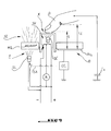
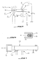
- Each proximity sensor such as D1 and D2 can be made up of a purely capacitive sensor static, i.e. without moving parts, as illustrated in Figures 4 and 5.
- Such a sensor typically includes an electrode constituted by an Afi frame electrically conductive, can be covered with a thin layer of material.
- the Afi frame is connected to a potential of reference through a serial circuit including a circuit electronic CC.
- this finger fulfills the role of a new frame itself, so that the Afi armature is connected to the potential benchmark through additional capacity variable Cs, which depends on the distance L separating the finger O of the armature Afi, and whose value is in permanently monitored by the CC electronic circuit.
- this circuit CC delivers the alert signal SA.
- each proximity detector such as D1 and D2, or at least one of them, can be consisting of a capacitive sensor with an armature mobile Am, as illustrated in figure 6.
- a variable capacity is formed between a fixed frame Af and this movable frame Am.
- the movable armature Am can be moved by the finger O against an elastic restoring force, which can be exercised by this Am armature itself if it is for example produced in the form of a capsule metal with elastic deformation.
- a circuit electronic (not shown) monitors the value of the variable capacity thus formed, this value depending on the distance separating the reinforcements Am and Af, and therefore of the distance separating the finger O from the fixed armature Af.
- the metal capsule can be used not only as reinforcement, but also as a switch, and form a galvanic contact when the second proximity condition is met.
- the setpoints K1 and K2 can take several embodiments, including being consisting of buttons, switches or potentiometers, FIG. 4 representing for example a setpoint K in the form of an actuating button an electric switch.
- the arrangement illustrated in this figure 4 highlights operates the process of the invention in such a way that the validation signal SV, for example SV1 or SV2, is not not produced by transmitter E, but by a source independent SL '.
- the validation signal SV is thus different from the SI information signal, i.e. SI1 signal or SI2 produced by the transmitter E1 or E2, so that the validation sub procedure can suppress signal SI1 or SI2 information as soon as the first condition of proximity ceases to be realized, the validation signal SV possibly taking over to inform the operator, when this is the case, that the function controlled by the set point K is active, and by example that the electric receiver R is supplied with Electric power.
- SI1 signal or SI2 produced by the transmitter E1 or E2
- the transmitter E1 or E2 continues to produce, as validation signal SV1 or SV2, the information signal SI1 or SI2 even after the first has disappeared proximity condition, as long as the function controlled by the set point K1 or K2 has been activated.
- detectors D1 and D2 are by example sensitive to the realization, to the location that each of them occupies, of a second condition of proximity, and operate each, in response to the achievement from this second proximity condition, a change status of the function assigned to the setpoint device associated.
- the second proximity condition is considered realized when the distance L which separates the finger O from the location X1 or X2 which it approaches is lower at a second determined threshold Lj, lower than the first threshold Li previously mentioned.
- the second proximity condition is considered performed when the finger O quickly approaches location X1 or X2, i.e. when the distance L separating this finger from the location X1 or X2 considered decreases at a speed dL / dT greater than a speed determined limit VL.
- detector D placed at the location considered delivers a setpoint signal Sk intended for change the state of the function controlled by this detector, which in this case also acts in setpoint K.
- the function assigned to this depositary body - detector can thus be controlled to pass from a state passive to active state by performing the second proximity condition.
- next realization of the second condition of proximity to the same location switches the function considered from its active state to its passive state, i.e. that the setpoint organ - detector D, K has bistable operation and systematically modifies the state of the function assigned to it each time that the second proximity condition is met.
- the deposit-taking bodies take the form of proximity detectors for example constituted by capacitive sensors, it is easy to arrange them under a translucent panel of the dashboard B of such so that they are invisible in the absence of everything signal.
- one or more reliefs forming one or more finger or hand touch guides O of the operator may then be wise to plan, on the dashboard B, one or more reliefs forming one or more finger or hand touch guides O of the operator.
Landscapes
- Engineering & Computer Science (AREA)
- Theoretical Computer Science (AREA)
- User Interface Of Digital Computer (AREA)
- Selective Calling Equipment (AREA)
- Switches That Are Operated By Magnetic Or Electric Fields (AREA)
- Electric Propulsion And Braking For Vehicles (AREA)
Abstract
Description
- la Figure 1 est un schéma général d'un réseau mettant en oeuvre le procédé de l'invention;
- les Figures 2A et 2B sont des diagrammes temporels illustrant de façon schématique le principe de l'invention;
- les Figures 3A à 3E sont des vues schématiques d'un tableau de bord géré par un procédé conforme à l'invention et représenté dans plusieurs états;
- la Figure 4 est un schéma d'un arrangement comprenant un organe de consigne, un détecteur et un émetteur, et dans lequel le détecteur et l'organe de consigne sont physiquement distincts l'un de l'autre, cet arrangement étant géré par un procédé conforme à l'invention;
- la Figure 5 est un schéma d'un arrangement comprenant un organe de consigne, un détecteur et un émetteur, et dans lequel le détecteur et l'organe de consigne sont physiquement indifférenciés l'un de l'autre, cet arrangement étant géré par un procédé conforme à l'invention;
- la Figure 6 est un schéma d'un détecteur utilisable dans un procédé conforme à l'invention; et
- la Figure 7 est une vue schématique d'un combinateur utilisable dans le procédé de l'invention.
Claims (21)
- Procédé de gestion et d'exploitation d'un réseau de commande multiplexé comprenant au moins des premier et second organes de consigne (K1, K2) appartenant à un ensemble d'organes de consigne multiplexés, une unité logique de commande (UL), et des premier et second organes commandés (W1, W2) appartenant à un ensemble d'organes commandés et respectivement associés aux premier et second organes de consigne (K1, K2), ce procédé comprenant au moins une procédure de consigne, dans laquelle au moins un organe de consigne (K1, K2), sélectionné parmi les premier et second organes de consigne par un organe de manipulation (O) tel qu'un doigt d'un opérateur, est actionné par cet organe de manipulation (O) et corrélativement déplacé d'un état initial vers un état final choisi parmi au moins deux états différents possibles, une procédure de scrutation, dans laquelle l'état de chaque organe de consigne (K1, K2) est scruté par l'unité logique (UL) au moins pendant chaque cycle d'une série de cycles de scrutation successifs (CSm) présentant chacun une durée au plus égale à une durée maximale déterminée (DT0) et une procédure de commande, dans laquelle l'unité logique (UL) réalise à chaque instant (Tm) un pilotage des premier et second organes commandés (W1, W2) en fonction des états respectifs des premier et second organes de consigne (K1, K2) tels que relevés au cours d'un cycle de scrutation (CSm-1) antérieur à cet instant, caractérisé en ce que la procédure de consigne met au moins en oeuvre un détecteur de proximité (D1) émettant un signal d'alerte (SA1) en cas de détection d'une première condition de proximité réalisée entre l'organe de manipulation (O) et le premier organe de consigne (K1) et annonçant la sélection de ce premier organe de consigne (K1), et en ce que le signal d'alerte (SA1) ainsi émis est utilisé par l'unité logique (UL) pour écourter la durée d'au moins un prochain cycle de scrutation (CSm+1) du premier organe de consigne (K1), et / ou préparer une modification du pilotage du premier organe commandé (W1), en fonction d'un possible changement d'état du premier organe de consigne (K1).
- Procédé suivant la revendication 1, caractérisé en ce que la première condition de proximité entre l'organe de manipulation (O) et un organe de consigne (K1, K2) est réalisée lorsque l'organe de manipulation (O) est séparé de cet organe de consigne (K1, K2) par une distance (L) inférieure à un premier seuil déterminé (Li).
- Procédé suivant la revendication 1 ou 2, caractérisé en ce que la procédure de consigne met au moins en oeuvre des premier et second détecteurs de proximité (D1, D2) émettant des premier et second signaux d'alerte respectifs (SA1, SA2) dès qu'ils détectent que la première condition de proximité est réalisée respectivement entre les premier et second organes de consigne (K1, K2) et l'organe de manipulation (O), annonçant respectivement la sélection des premier et second organes de consigne (K1, K2), et en ce que chaque signal d'alerte (SA1, SA2) ainsi émis est utilisé par l'unité logique (UL) pour écourter la durée d'au moins un prochain cycle de scrutation (CSm+1) de l'organe de consigne (K1, K2) sélectionné ou en passe de l'être, et / ou préparer, en fonction d'un possible changement d'état de l'organe de consigne (K1, K2) sélectionné ou en passe de l'être, une modification du pilotage de l'organe commandé (W1, W2) qui est associé à l'organe de consigne (K1, K2) sélectionné ou en passe de l'être.
- Procédé suivant la revendication 3, caractérisé en ce que les premier et second organes de consigne (K1, K2) sont disposés en des premier et second emplacements respectifs (X1, X2) auxquels sont aussi respectivement disposés les premier et second détecteurs de proximité (D1, D2), et des premier et second émetteurs (E1, E2) de signaux d'information avec lesquels les premier et second organes de consigne (K1, K2) et les premier et second détecteurs de proximité (D1, D2) sont ainsi respectivement mis en correspondance, et en ce que chaque émetteur (E1, E2) produit, en cas d'émission d'un signal d'alerte (SA1, SA2) par le détecteur de proximité correspondant (D1, D2), un signal d'information (SI1, SI2) rappelant à l'opérateur quel organe commandé (W1, W2) est associé à l'organe de consigne (K1, K2) qui correspond à l'émetteur (E1, E2) de ce signal d'information.
- Procédé suivant l'une quelconque des revendications 1 à 4, caractérisé en ce que les premier et second organes de consigne (K1, K2) sont disposés en des premier et second emplacements respectifs (X1, X2), en ce que chacun des premier et second organes de consigne (K1, K2) adopte sélectivement un état actif ou un état passif, et en ce que la procédure de commande comprend une sous-procédure de validation, consistant au moins à produire un signal de validation (SV1, SV2) à chacun des premier et second emplacements (X1, X2) où est disposé un organe de consigne (K1, K2) placé dans son état actif.
- Procédé suivant la revendication 1 ou 2,
caractérisé en ce que le détecteur de proximité (D) est disposé de manière à pouvoir détecter une réalisation de la première condition de proximité entre l'organe de manipulation (O) et l'un ou l'autre des premier et second organes de consigne (K1, K2), le signal d'alerte (SA) émis par ce détecteur de proximité (D) annonçant ainsi la sélection de l'un ou l'autre des premier et second organes de consigne (K1, K2), et en ce que ce signal d'alerte (SA) est utilisé par l'unité logique (UL) pour écourter la durée d'au moins un prochain cycle de scrutation (CSm+1) des premier et second organes de consigne (K1, K2), et / ou préparer une modification du pilotage des premier et second organes commandés (W1, W2), en fonction d'un possible changement des états des premier et second organes de consigne (K1, K2). - Procédé suivant l'une quelconque des revendications précédentes, caractérisé en ce que les premier et second organes de consigne (K1, K2) sont constitués par des boutons, des interrupteurs ou des potentiomètres.
- Procédé suivant l'une quelconque des revendications 1 à 5 combinée à la revendication 3, caractérisé en ce que les premier et second détecteurs (D1, D2) constituent eux-mêmes les premier et second organes de consigne (K1, K2), chaque organe de consigne (K1, K2) étant sensible à une seconde condition de proximité entre lui-même et l'organe de manipulation (O), et changeant d'état par réalisation de cette seconde condition de proximité.
- Procédé suivant la revendication 8, caractérisé en ce que chacun des premier et second organes de consigne (K1, K2) passe d'un état passif à un état actif par réalisation de la seconde condition de proximité.
- Procédé suivant la revendication 8 ou 9, caractérisé en ce que chacun des premier et second organes de consigne (K1, K2) passe d'un état actif à un état passif par réalisation de la seconde condition de proximité.
- Procédé suivant l'une quelconque des revendications 8 à 10 combinée à la revendication 2, caractérisé en ce que la seconde condition de proximité entre l'organe de manipulation (O) et un organe de consigne (K1, K2) est réalisée lorsque l'organe de manipulation (O) est séparé de cet organe de consigne (K1, K2) par une distance (L) inférieure à un second seuil déterminé (Lj), inférieur au premier seuil (Li).
- Procédé suivant l'une quelconque des revendications 8 à 10, caractérisé en ce que la seconde condition de proximité entre l'organe de manipulation (O) et un organe de consigne (K1, K2) est réalisée lorsque l'organe de manipulation (O) est séparé de cet organe de consigne (K1, K2) par une distance (L) qui diminue à une vitesse (dL/dT) supérieure à une vitesse limite déterminée (VL) .
- Procédé suivant l'une quelconque des revendications précédentes combinée à la revendication 4, caractérisé en ce que le signal d'information (SI1, SI2) est un signal lumineux, un signal sonore, un signal vibratoire, ou un message parlé.
- Procédé suivant l'une quelconque des revendications précédentes combinée à la revendication 5, caractérisé en ce que le signal de validation (SV1, SV2) est un signal lumineux.
- Procédé suivant l'une quelconque des revendications précédentes, caractérisé en ce que le réseau de commande multiplexé est embarqué sur un véhicule automobile, et en ce que chaque emplacement (X1, X2) appartient à un poste de conduite de ce véhicule.
- Procédé suivant l'une quelconque des revendications précédentes combinée aux revendications 4 et 15, caractérisé en ce qu'il met en oeuvre, sur le poste de conduite, au moins un relief formant un guide tactile pour l'organe de manipulation (O).
- Procédé suivant l'une quelconque des revendications précédentes combinée aux revendications 4, 5 et 15, caractérisé en ce que les premier et second emplacements (X1, X2) appartiennent à un tableau de bord (B) du véhicule et en ce qu'en l'absence de tout signal d'information (SI1, SI2) et de tout signal de validation (SV1, SV2) , les premier et second emplacements (X1, X2) sont indifférenciés.
- Procédé suivant l'une quelconque des revendications précédentes combinée aux revendications 4, 5 et 15, caractérisé en ce que les premier et seconds détecteurs de proximité (D1, D2) et les premier et second émetteurs (E1, E2) de signaux d'information sont disposés sous un panneau translucide d'un tableau de bord (B) du véhicule.
- Procédé suivant les revendications 7 et 15 considérées dans leur rattachement à la revendication 6, caractérisé en ce que le détecteur de proximité est porté par un combinateur (CB) du véhicule, et en ce que les premier et second organes de consigne (K1, K2) sont constitués par des contacts électriques et / ou des rhéostats portés par le combinateur (CB).
- Procédé suivant l'une quelconque des revendications précédentes combinée à la revendication 3, caractérisé en ce que l'un au moins des premier et second détecteurs de proximité (D1, D2) est un capteur capacitif dépourvu de pièce mobile.
- Procédé suivant l'une quelconque des revendications précédentes combinée à la revendication 3, caractérisé en ce que l'un au moins des premier et second détecteurs de proximité (D1, D2) est un capteur capacitif doté d'une armature mobile (Am) sélectivement déplacée par l'organe de manipulation (O) à l'encontre d'une force élastique de rappel.
Applications Claiming Priority (2)
| Application Number | Priority Date | Filing Date | Title |
|---|---|---|---|
| FR0115938A FR2833391B1 (fr) | 2001-12-10 | 2001-12-10 | Procede de gestion et d'exploitation d'un reseau comprenant des organes de consigne multiplexes, notamment pour vehicule automobile |
| FR0115938 | 2001-12-10 |
Publications (2)
| Publication Number | Publication Date |
|---|---|
| EP1318607A1 true EP1318607A1 (fr) | 2003-06-11 |
| EP1318607B1 EP1318607B1 (fr) | 2005-05-11 |
Family
ID=8870298
Family Applications (1)
| Application Number | Title | Priority Date | Filing Date |
|---|---|---|---|
| EP02292931A Expired - Lifetime EP1318607B1 (fr) | 2001-12-10 | 2002-11-27 | Procédé de gestion et d'exploitation d'un réseau comprenant des organes de consigne multiplexes, notamment pour véhicule automobile |
Country Status (4)
| Country | Link |
|---|---|
| EP (1) | EP1318607B1 (fr) |
| AT (1) | ATE295631T1 (fr) |
| DE (1) | DE60204106T2 (fr) |
| FR (1) | FR2833391B1 (fr) |
Citations (3)
| Publication number | Priority date | Publication date | Assignee | Title |
|---|---|---|---|---|
| FR2670635A1 (fr) * | 1990-12-13 | 1992-06-19 | Sextant Avionique | Dispositif de commutation a double mode de fonctionnement. |
| DE19609743A1 (de) * | 1996-03-13 | 1997-09-18 | Ans W Hens & Partner Gmbh Anla | Verfahren zum Informieren über gespeicherte Daten und Vorrichtung zur Durchführung des Verfahrens |
| US5844500A (en) * | 1991-05-31 | 1998-12-01 | U.S. Philips Corporation | Device with a human-machine interface |
-
2001
- 2001-12-10 FR FR0115938A patent/FR2833391B1/fr not_active Expired - Fee Related
-
2002
- 2002-11-27 AT AT02292931T patent/ATE295631T1/de not_active IP Right Cessation
- 2002-11-27 EP EP02292931A patent/EP1318607B1/fr not_active Expired - Lifetime
- 2002-11-27 DE DE60204106T patent/DE60204106T2/de not_active Expired - Fee Related
Patent Citations (3)
| Publication number | Priority date | Publication date | Assignee | Title |
|---|---|---|---|---|
| FR2670635A1 (fr) * | 1990-12-13 | 1992-06-19 | Sextant Avionique | Dispositif de commutation a double mode de fonctionnement. |
| US5844500A (en) * | 1991-05-31 | 1998-12-01 | U.S. Philips Corporation | Device with a human-machine interface |
| DE19609743A1 (de) * | 1996-03-13 | 1997-09-18 | Ans W Hens & Partner Gmbh Anla | Verfahren zum Informieren über gespeicherte Daten und Vorrichtung zur Durchführung des Verfahrens |
Also Published As
| Publication number | Publication date |
|---|---|
| ATE295631T1 (de) | 2005-05-15 |
| DE60204106T2 (de) | 2006-01-19 |
| FR2833391B1 (fr) | 2004-03-19 |
| FR2833391A1 (fr) | 2003-06-13 |
| DE60204106D1 (de) | 2005-06-16 |
| EP1318607B1 (fr) | 2005-05-11 |
Similar Documents
| Publication | Publication Date | Title |
|---|---|---|
| EP4263262B1 (fr) | Système de commande, et véhicule automobile associé | |
| FR2790228A1 (fr) | Dispositif de commande d'un systeme de regulation d'allure pour vehicule automobile | |
| WO2011004107A1 (fr) | Procede et dispositif de detection d'une situation de transport d'un vehicule en mode veille, et vehicule equipe d'un tel dispositif | |
| FR2890351A1 (fr) | Centrale de commande de bord pour vehicule automobile. | |
| FR2826999A1 (fr) | Systeme de fermeture de porte de vehicule automobile | |
| EP1456489B1 (fr) | Systeme de detection de presence d'un utilisateur notamment pour vehicule automobile | |
| FR2953472A1 (fr) | Procede de gestion d'une installation de freins de vehicule et installation pour la mise en oeuvre du procede | |
| WO2013091823A1 (fr) | Procede d'acces mains libres a un vehicule automobile et de surveillance de la pression des pneumatiques montes sur ce vehicule | |
| WO2013153309A1 (fr) | Procede de gestion de commande de retrogradage d'une boite de vitesses automatique, et dispositif correspondant | |
| EP1318607B1 (fr) | Procédé de gestion et d'exploitation d'un réseau comprenant des organes de consigne multiplexes, notamment pour véhicule automobile | |
| EP1824700B1 (fr) | Procede et programme informatique place a bord d'un vehicule et permettant de regler la distance par rapport a un vehicule precedant | |
| FR3048669A1 (fr) | Systeme d'enclenchement simplifie pour une section d'aiguillage | |
| WO2016066254A1 (fr) | Procede de pilotage d'un processeur d'un boitier electronique monte sur une roue d'un vehicule automobile | |
| EP1953027B1 (fr) | Dispositif de commande d'un engin de manutention | |
| EP0733524A1 (fr) | Antivol électrique, notamment pour un véhicule automobile | |
| EP4259492B1 (fr) | Procédé de pilotage d'un dispositif d'alerte de non bouclage de ceinture de sécurité | |
| US20240124012A1 (en) | Method, Device and Storage Medium for Scheduling Notification Based on Driving assistance features | |
| FR2833387A1 (fr) | Procede de gestion et d'exploitation d'un ensemble d'organes de consigne d'un vehicule automobile, incluant l'emission d'un signal sonore | |
| FR2769884A1 (fr) | Systeme de freinage pour vehicule automobile comportant un mode de freinage assiste | |
| FR2833386A1 (fr) | Procede de gestion et d'exploitation d'un ensemble d'organes de consigne d'un vehicule automobile, incluant l'emission d'un signal lumineux | |
| WO2011114015A1 (fr) | Dispositif de commutation pour haut de colonne de direction de véhicule automobile | |
| EP1861266B1 (fr) | Procédé de détection d' un defaut d' émission d' une unité roue appartenant à un système de surveillance de la pression des pneus | |
| FR3093954A1 (fr) | Procédé d’ajustement d’une périodicité de communication entre une unité roue et un dispositif habilité | |
| FR2923012A1 (fr) | Procede de determination d'une probabilite de presence de chaines a neige sur les roues d'un vehicule automobile, procede de limitation du braquage des roues d'un vehicule utilisant le procede precedent et systeme de mise en oeuvre | |
| EP1093101B1 (fr) | Procédé de synchronisation automatique entre une clef de télécommande et un calculateur associé |
Legal Events
| Date | Code | Title | Description |
|---|---|---|---|
| PUAI | Public reference made under article 153(3) epc to a published international application that has entered the european phase |
Free format text: ORIGINAL CODE: 0009012 |
|
| AK | Designated contracting states |
Designated state(s): AT BE BG CH CY CZ DE DK EE ES FI FR GB GR IE IT LI LU MC NL PT SE SK TR |
|
| AX | Request for extension of the european patent |
Extension state: AL LT LV MK RO SI |
|
| 17P | Request for examination filed |
Effective date: 20031121 |
|
| AKX | Designation fees paid |
Designated state(s): AT BE BG CH CY CZ DE DK EE ES FI FR GB GR IE IT LI LU MC NL PT SE SK TR |
|
| 17Q | First examination report despatched |
Effective date: 20040524 |
|
| GRAP | Despatch of communication of intention to grant a patent |
Free format text: ORIGINAL CODE: EPIDOSNIGR1 |
|
| RIN1 | Information on inventor provided before grant (corrected) |
Inventor name: CHIARIGLIONE, EMMANUEL Inventor name: SIMON, FREDERIC |
|
| GRAS | Grant fee paid |
Free format text: ORIGINAL CODE: EPIDOSNIGR3 |
|
| GRAA | (expected) grant |
Free format text: ORIGINAL CODE: 0009210 |
|
| AK | Designated contracting states |
Kind code of ref document: B1 Designated state(s): AT BE BG CH CY CZ DE DK EE ES FI FR GB GR IE IT LI LU MC NL PT SE SK TR |
|
| PG25 | Lapsed in a contracting state [announced via postgrant information from national office to epo] |
Ref country code: NL Free format text: LAPSE BECAUSE OF FAILURE TO SUBMIT A TRANSLATION OF THE DESCRIPTION OR TO PAY THE FEE WITHIN THE PRESCRIBED TIME-LIMIT Effective date: 20050511 Ref country code: TR Free format text: LAPSE BECAUSE OF FAILURE TO SUBMIT A TRANSLATION OF THE DESCRIPTION OR TO PAY THE FEE WITHIN THE PRESCRIBED TIME-LIMIT Effective date: 20050511 Ref country code: IE Free format text: LAPSE BECAUSE OF FAILURE TO SUBMIT A TRANSLATION OF THE DESCRIPTION OR TO PAY THE FEE WITHIN THE PRESCRIBED TIME-LIMIT Effective date: 20050511 Ref country code: SK Free format text: LAPSE BECAUSE OF FAILURE TO SUBMIT A TRANSLATION OF THE DESCRIPTION OR TO PAY THE FEE WITHIN THE PRESCRIBED TIME-LIMIT Effective date: 20050511 Ref country code: EE Free format text: LAPSE BECAUSE OF FAILURE TO SUBMIT A TRANSLATION OF THE DESCRIPTION OR TO PAY THE FEE WITHIN THE PRESCRIBED TIME-LIMIT Effective date: 20050511 Ref country code: CZ Free format text: LAPSE BECAUSE OF FAILURE TO SUBMIT A TRANSLATION OF THE DESCRIPTION OR TO PAY THE FEE WITHIN THE PRESCRIBED TIME-LIMIT Effective date: 20050511 Ref country code: FI Free format text: LAPSE BECAUSE OF FAILURE TO SUBMIT A TRANSLATION OF THE DESCRIPTION OR TO PAY THE FEE WITHIN THE PRESCRIBED TIME-LIMIT Effective date: 20050511 Ref country code: AT Free format text: LAPSE BECAUSE OF FAILURE TO SUBMIT A TRANSLATION OF THE DESCRIPTION OR TO PAY THE FEE WITHIN THE PRESCRIBED TIME-LIMIT Effective date: 20050511 |
|
| REG | Reference to a national code |
Ref country code: GB Ref legal event code: FG4D Free format text: NOT ENGLISH |
|
| REG | Reference to a national code |
Ref country code: CH Ref legal event code: EP |
|
| REG | Reference to a national code |
Ref country code: IE Ref legal event code: FG4D Free format text: LANGUAGE OF EP DOCUMENT: FRENCH |
|
| REF | Corresponds to: |
Ref document number: 60204106 Country of ref document: DE Date of ref document: 20050616 Kind code of ref document: P |
|
| PG25 | Lapsed in a contracting state [announced via postgrant information from national office to epo] |
Ref country code: SE Free format text: LAPSE BECAUSE OF FAILURE TO SUBMIT A TRANSLATION OF THE DESCRIPTION OR TO PAY THE FEE WITHIN THE PRESCRIBED TIME-LIMIT Effective date: 20050811 Ref country code: GR Free format text: LAPSE BECAUSE OF FAILURE TO SUBMIT A TRANSLATION OF THE DESCRIPTION OR TO PAY THE FEE WITHIN THE PRESCRIBED TIME-LIMIT Effective date: 20050811 Ref country code: BG Free format text: LAPSE BECAUSE OF FAILURE TO SUBMIT A TRANSLATION OF THE DESCRIPTION OR TO PAY THE FEE WITHIN THE PRESCRIBED TIME-LIMIT Effective date: 20050811 Ref country code: DK Free format text: LAPSE BECAUSE OF FAILURE TO SUBMIT A TRANSLATION OF THE DESCRIPTION OR TO PAY THE FEE WITHIN THE PRESCRIBED TIME-LIMIT Effective date: 20050811 |
|
| PG25 | Lapsed in a contracting state [announced via postgrant information from national office to epo] |
Ref country code: ES Free format text: LAPSE BECAUSE OF FAILURE TO SUBMIT A TRANSLATION OF THE DESCRIPTION OR TO PAY THE FEE WITHIN THE PRESCRIBED TIME-LIMIT Effective date: 20050822 |
|
| GBT | Gb: translation of ep patent filed (gb section 77(6)(a)/1977) |
Effective date: 20050817 |
|
| PG25 | Lapsed in a contracting state [announced via postgrant information from national office to epo] |
Ref country code: PT Free format text: LAPSE BECAUSE OF FAILURE TO SUBMIT A TRANSLATION OF THE DESCRIPTION OR TO PAY THE FEE WITHIN THE PRESCRIBED TIME-LIMIT Effective date: 20051019 |
|
| NLV1 | Nl: lapsed or annulled due to failure to fulfill the requirements of art. 29p and 29m of the patents act | ||
| PG25 | Lapsed in a contracting state [announced via postgrant information from national office to epo] |
Ref country code: CY Free format text: LAPSE BECAUSE OF FAILURE TO SUBMIT A TRANSLATION OF THE DESCRIPTION OR TO PAY THE FEE WITHIN THE PRESCRIBED TIME-LIMIT Effective date: 20051127 |
|
| PG25 | Lapsed in a contracting state [announced via postgrant information from national office to epo] |
Ref country code: BE Free format text: LAPSE BECAUSE OF NON-PAYMENT OF DUE FEES Effective date: 20051130 Ref country code: MC Free format text: LAPSE BECAUSE OF NON-PAYMENT OF DUE FEES Effective date: 20051130 Ref country code: LU Free format text: LAPSE BECAUSE OF NON-PAYMENT OF DUE FEES Effective date: 20051130 |
|
| REG | Reference to a national code |
Ref country code: IE Ref legal event code: FD4D |
|
| PLBE | No opposition filed within time limit |
Free format text: ORIGINAL CODE: 0009261 |
|
| STAA | Information on the status of an ep patent application or granted ep patent |
Free format text: STATUS: NO OPPOSITION FILED WITHIN TIME LIMIT |
|
| 26N | No opposition filed |
Effective date: 20060214 |
|
| PG25 | Lapsed in a contracting state [announced via postgrant information from national office to epo] |
Ref country code: CH Free format text: LAPSE BECAUSE OF NON-PAYMENT OF DUE FEES Effective date: 20061130 Ref country code: LI Free format text: LAPSE BECAUSE OF NON-PAYMENT OF DUE FEES Effective date: 20061130 |
|
| REG | Reference to a national code |
Ref country code: GB Ref legal event code: 746 Effective date: 20070117 |
|
| REG | Reference to a national code |
Ref country code: CH Ref legal event code: PL |
|
| BERE | Be: lapsed |
Owner name: PEUGEOT CITROEN AUTOMOBILES SA Effective date: 20051130 |
|
| PGFP | Annual fee paid to national office [announced via postgrant information from national office to epo] |
Ref country code: DE Payment date: 20081126 Year of fee payment: 7 |
|
| PGFP | Annual fee paid to national office [announced via postgrant information from national office to epo] |
Ref country code: IT Payment date: 20081117 Year of fee payment: 7 |
|
| PGFP | Annual fee paid to national office [announced via postgrant information from national office to epo] |
Ref country code: FR Payment date: 20081126 Year of fee payment: 7 |
|
| PGFP | Annual fee paid to national office [announced via postgrant information from national office to epo] |
Ref country code: GB Payment date: 20081029 Year of fee payment: 7 |
|
| GBPC | Gb: european patent ceased through non-payment of renewal fee |
Effective date: 20091127 |
|
| REG | Reference to a national code |
Ref country code: FR Ref legal event code: ST Effective date: 20100730 |
|
| PG25 | Lapsed in a contracting state [announced via postgrant information from national office to epo] |
Ref country code: FR Free format text: LAPSE BECAUSE OF NON-PAYMENT OF DUE FEES Effective date: 20091130 |
|
| PG25 | Lapsed in a contracting state [announced via postgrant information from national office to epo] |
Ref country code: DE Free format text: LAPSE BECAUSE OF NON-PAYMENT OF DUE FEES Effective date: 20100601 |
|
| PG25 | Lapsed in a contracting state [announced via postgrant information from national office to epo] |
Ref country code: GB Free format text: LAPSE BECAUSE OF NON-PAYMENT OF DUE FEES Effective date: 20091127 |
|
| PG25 | Lapsed in a contracting state [announced via postgrant information from national office to epo] |
Ref country code: IT Free format text: LAPSE BECAUSE OF NON-PAYMENT OF DUE FEES Effective date: 20091127 |