EP1318506A1 - Optical information recording medium and recording/reproducing method therefor - Google Patents
Optical information recording medium and recording/reproducing method therefor Download PDFInfo
- Publication number
- EP1318506A1 EP1318506A1 EP01955644A EP01955644A EP1318506A1 EP 1318506 A1 EP1318506 A1 EP 1318506A1 EP 01955644 A EP01955644 A EP 01955644A EP 01955644 A EP01955644 A EP 01955644A EP 1318506 A1 EP1318506 A1 EP 1318506A1
- Authority
- EP
- European Patent Office
- Prior art keywords
- laser light
- recording medium
- state
- land
- substrate
- Prior art date
- Legal status (The legal status is an assumption and is not a legal conclusion. Google has not performed a legal analysis and makes no representation as to the accuracy of the status listed.)
- Withdrawn
Links
Images


Classifications
-
- G—PHYSICS
- G11—INFORMATION STORAGE
- G11B—INFORMATION STORAGE BASED ON RELATIVE MOVEMENT BETWEEN RECORD CARRIER AND TRANSDUCER
- G11B7/00—Recording or reproducing by optical means, e.g. recording using a thermal beam of optical radiation by modifying optical properties or the physical structure, reproducing using an optical beam at lower power by sensing optical properties; Record carriers therefor
- G11B7/24—Record carriers characterised by shape, structure or physical properties, or by the selection of the material
-
- G—PHYSICS
- G11—INFORMATION STORAGE
- G11B—INFORMATION STORAGE BASED ON RELATIVE MOVEMENT BETWEEN RECORD CARRIER AND TRANSDUCER
- G11B7/00—Recording or reproducing by optical means, e.g. recording using a thermal beam of optical radiation by modifying optical properties or the physical structure, reproducing using an optical beam at lower power by sensing optical properties; Record carriers therefor
- G11B7/004—Recording, reproducing or erasing methods; Read, write or erase circuits therefor
- G11B7/005—Reproducing
- G11B7/0051—Reproducing involving phase depth effects
-
- G—PHYSICS
- G11—INFORMATION STORAGE
- G11B—INFORMATION STORAGE BASED ON RELATIVE MOVEMENT BETWEEN RECORD CARRIER AND TRANSDUCER
- G11B7/00—Recording or reproducing by optical means, e.g. recording using a thermal beam of optical radiation by modifying optical properties or the physical structure, reproducing using an optical beam at lower power by sensing optical properties; Record carriers therefor
- G11B7/24—Record carriers characterised by shape, structure or physical properties, or by the selection of the material
- G11B7/2407—Tracks or pits; Shape, structure or physical properties thereof
- G11B7/24073—Tracks
- G11B7/24079—Width or depth
-
- G—PHYSICS
- G11—INFORMATION STORAGE
- G11B—INFORMATION STORAGE BASED ON RELATIVE MOVEMENT BETWEEN RECORD CARRIER AND TRANSDUCER
- G11B7/00—Recording or reproducing by optical means, e.g. recording using a thermal beam of optical radiation by modifying optical properties or the physical structure, reproducing using an optical beam at lower power by sensing optical properties; Record carriers therefor
- G11B7/004—Recording, reproducing or erasing methods; Read, write or erase circuits therefor
- G11B7/0045—Recording
- G11B7/00454—Recording involving phase-change effects
-
- G—PHYSICS
- G11—INFORMATION STORAGE
- G11B—INFORMATION STORAGE BASED ON RELATIVE MOVEMENT BETWEEN RECORD CARRIER AND TRANSDUCER
- G11B7/00—Recording or reproducing by optical means, e.g. recording using a thermal beam of optical radiation by modifying optical properties or the physical structure, reproducing using an optical beam at lower power by sensing optical properties; Record carriers therefor
- G11B7/004—Recording, reproducing or erasing methods; Read, write or erase circuits therefor
- G11B7/005—Reproducing
-
- G—PHYSICS
- G11—INFORMATION STORAGE
- G11B—INFORMATION STORAGE BASED ON RELATIVE MOVEMENT BETWEEN RECORD CARRIER AND TRANSDUCER
- G11B7/00—Recording or reproducing by optical means, e.g. recording using a thermal beam of optical radiation by modifying optical properties or the physical structure, reproducing using an optical beam at lower power by sensing optical properties; Record carriers therefor
- G11B7/004—Recording, reproducing or erasing methods; Read, write or erase circuits therefor
- G11B7/006—Overwriting
-
- G—PHYSICS
- G11—INFORMATION STORAGE
- G11B—INFORMATION STORAGE BASED ON RELATIVE MOVEMENT BETWEEN RECORD CARRIER AND TRANSDUCER
- G11B7/00—Recording or reproducing by optical means, e.g. recording using a thermal beam of optical radiation by modifying optical properties or the physical structure, reproducing using an optical beam at lower power by sensing optical properties; Record carriers therefor
- G11B7/24—Record carriers characterised by shape, structure or physical properties, or by the selection of the material
- G11B7/26—Apparatus or processes specially adapted for the manufacture of record carriers
Definitions
- the present invention relates to an optical information recording medium for allowing information to be recorded thereon, erased and reproduced therefrom and rewritten thereon at a high density and a high speed using optical means such as laser irradiation or like; a method for performing information recording, erasing and reproduction using the optical information recording medium; and an apparatus for performing information recording on, erasing from and reproduction from the optical information recording medium.
- Optical information recording media such as magneto-optic recording media, phase-change recording media and the like are known as large capacity media for allowing information to be recorded and rewritten thereon at a high density.
- these optical recording media utilize a change in an optical characteristic of a recording material, generated by locally irradiating the recording material with laser light.
- optical information recording media which have great advantages of allowing random access when necessary and having satisfactory portability, have recently become more important. They are in greater demand in various fields, for example, for recording and storing individual data, video information or the like obtained using a computer; for use in medical and academic fields; as recording media for portable digital video recorders; or as a substitute for home-use video tape recorders. Due to the attainment of improved performance in applications and image information, there is a corresponding need for such optical information recording media to have a larger capacity (a higher density) and to operate at a higher speed.
- Japanese Laid-Open Publication No. 11-195243 discloses a technique for performing recording on and reproduction from a multi-layer optical disc using an optical system having a high numerical aperture for realizing a higher capacity. This technique reduces a thickness of a transparent substrate to obtain a disc skew margin with certainty.
- Japanese Laid-Open Publication No. 11-195243 does not disclose any technique for solving the problem of adjacent erasing, caused when high density recording is performed using short-wavelength light, or using an optical system having a high numerical aperture.
- the publication does not disclose any technique for achieving both restriction of adjacent erasing and a high C/N ratio.
- the publication provides no indication as to which recording system (land system, groove system, etc.) is superior for solving the above-described problem.
- Japanese Laid-Open Publication No. 11-120565 discloses a technique for performing information recording and reproduction using a thin substrate and an optical system having a high numerical aperture. According to this technique, it is determined whether information is recorded in either only lands or only grooves or in both the lands and the grooves, in accordance with the relationship between the spot diameter and the width of the track, so as to realize compatibility in terms of light of different wavelengths or optical systems of different numerical apertures.
- the publication describes that even if the standards for recording and reproduction are updated, this technique still allows information to be recorded and reproduced with either the pre-update or post-update standards. According to this publication, when the sum of the land width and the groove width is equal to or greater than twice the spot diameter, information is recorded in both the lands and the grooves.
- Japanese Laid-Open Publication No. 11-120565 does not describe the problem of adjacent erasing which is caused when high density recording is performed using an optical system having a high numerical aperture or using short-wavelength light.
- the technique disclosed in this publication determines the recording system merely in accordance with the relationship between the spot diameter and the track width.
- Japanese Laid-Open Publication No. 5-128589 discloses a technique for determining whether information is to be recorded in grooves or lands in accordance with the polarity of the phase of the recording medium which changes before and after the recording.
- Japanese Laid-Open Publication No. 5-128589 does not describe the problem of adjacent erasing, which is caused when high density recording is performed.
- the technique disclosed in this publication determines whether information is to be recorded in the lands or the grooves merely in accordance with the polarity of the phase difference.
- the present invention has been made in light of the above-described problems and has an objective of providing an optical information recording medium which provides both a sufficient C/N ratio and reduction in adjacent erasing even when high density recording is performed.
- the present invention provides an optical information recording medium including a first substrate; a second substrate; and a recording layer formed between the first substrate and the second substrate.
- the optical information recording medium includes lands and grooves, and a distance between a light source of laser light irradiating the optical information recording medium and the lands is larger than a distance between the light source and the grooves.
- the lands are formed in the optical information recording medium at a pitch of less than or equal to 0.40 ⁇ m. Each land is either in a first state having a first reflectance or in a second state having a second reflectance lower than the first reflectance, and the first state and the second state are reversibly changeable by the irradiation of the laser light.
- ⁇ 1 - ⁇ 2 which is a difference between ⁇ 1 and ⁇ 2 fulfills 2n ⁇ ⁇ ⁇ 1 - ⁇ 2 ⁇ ⁇ + 2n ⁇ (n is an arbitrary integer) where ⁇ 1 is a phase of light reflected by a portion of the land which is in the first state and ⁇ 2 is a phase of light reflected by a portion of the land which is in the second state.
- ⁇ 1 is a phase of light reflected by a portion of the land which is in the first state
- ⁇ 2 is a phase of light reflected by a portion of the land which is in the second state.
- ⁇ 1 - ⁇ 2 when a land is irradiated with the laser light for reproduction, ⁇ 1 - ⁇ 2 , which is a difference between ⁇ 1 and ⁇ 2, fulfills 0.1n ⁇ + 2n ⁇ ⁇ ⁇ 1 - ⁇ 2 ⁇ 0.5 ⁇ + 2n ⁇ (n is an arbitrary integer) where ⁇ 1 is a phase of light reflected by a portion of the lands which is in the first state and ⁇ 2 is a phase of light reflected by a portion of the lands which is in the second state.
- the first substrate has a thickness of greater than or equal to 0.1 mm and less than or equal to 0.4 mm
- the second substrate has a thickness of greater than or equal to 0.4 mm.
- the optical information recording medium further includes a protective layer formed between the first substrate and the recording layer, and the protective layer has a thickness d 1 fulfilling 0.1 ⁇ /n 2 + n ⁇ /( 2 x n 2 ) ⁇ d 1 ⁇ 0.4 ⁇ /n 2 + n ⁇ /(2 x n 2 ) (n is an arbitrary integer), where ⁇ is a wavelength of the laser light and n 2 is a refractive index of the protective layer.
- the recording layer has a thickness greater than or equal to 1 nm and less than or equal to 12 nm.
- the optical information recording medium further includes a guide groove for the laser light in a surface of at least one of the first substrate and the second substrate facing the recording layer, and the guide groove has a depth d 2 fulfilling ⁇ /20n 1 ⁇ d 2 ⁇ /8n 1 , where ⁇ is a wavelength of the laser light and n 1 is a refractive index of the substrate on which the laser light is incident first.
- the recording layer includes at least one of Sb and Te.
- At least two recording layers are included.
- the guide grooves are formed at a pitch of less than or equal to 0.40 ⁇ m.
- the optical information recording medium fulfills Tp/4 ⁇ w ⁇ Tp/2 where w is a width of a recording mark formed on the lands by the irradiation of the laser light and Tp is the pitch of the lands.
- the present invention further provides a method for recording information on, and erasing and reproducing information from an optical information recording medium comprising a first substrate; a second substrate: and a recording layer formed between the first substrate and the second substrate.
- the optical information recording medium includes lands and grooves, and a distance between a light source of laser light irradiating the optical information recording medium and the lands is larger than a distance between the light source and the grooves.
- the lands are formed in the optical information recording medium at a pitch of less than or equal to 0.40 ⁇ m.
- Each land is either in a first state having a first reflectance or in a second state having a second reflectance lower than the first reflectance, and the first state and the second state are reversibly changeable by the irradiation of the laser light.
- ⁇ 1 - ⁇ 2 which is a difference between ⁇ 1 and ⁇ 2 , fulfills 2n ⁇ ⁇ ⁇ 1 - ⁇ 2 ⁇ ⁇ + 2n ⁇ (n is an arbitrary integer) where ⁇ 1 is a phase of light reflected by a portion of the land which is in the first state and ⁇ 2 is a phase of light reflected by a portion of the land which is in the second state.
- The includes the steps of modulating a power level of the laser light between P 1 and P 2 to record the information in the land or erase the information from the land; and irradiating the land with laser light for reproduction having a power level of P 3 to reproduce information recorded in the land.
- P 1 is a power level of the laser light which can change the land from the second state to the first state by the irradiation of the laser light
- P 2 is a power level of the laser light which can change the land from the first state to the second state by the irradiation of the laser light
- P 3 is power level of the laser light which does not change the reflectance of the land but provides a sufficient amount of reflected light for reproducing the recorded information by the irradiation of the laser light, P 3 being lower than P 1 and P 2 .
- the first substrate has a thickness of less than or equal to 0.4 mm
- the second substrate has a thickness of greater than or equal to 0.4 mm
- the laser light is obtained by a numerical aperture of greater than or equal to 0.70.
- the laser light has a wavelength of less than or equal to 450 nm.
- the present invention further provides an apparatus for recording information on, and erasing and reproducing information from an optical information recording medium.
- the apparatus includes a light source for emitting laser light; an optical system for collecting the laser light emitted by the laser light source on the optical information recording medium; and a laser light control section for controlling the laser light source.
- the optical information recording medium includes a first substrate; a second substrate; and a recording layer formed between the first substrate and the second substrate.
- the optical information recording medium includes lands and grooves, and a distance between a light source of laser light irradiating the optical information recording medium and the lands is larger than a distance between the light source and the grooves.
- the lands are formed in the optical information recording medium at a pitch of less than or equal to 0.40 ⁇ m.
- Each land is either in a first state having a first reflectance or in a second state having a second reflectance lower than the first reflectance, and the first state and the second state are reversibly changeable by the irradiation of the laser light.
- ⁇ 1 - ⁇ 2 which is a difference between ⁇ 1 and ⁇ 2 , fulfills 2n ⁇ ⁇ 1 - ⁇ 2 ⁇ ⁇ + 2n ⁇ (n is an arbitrary integer) where ⁇ 1 is a phase of light reflected by a portion of the land which is in the first state and ⁇ 2 is a phase of light reflected by a portion of the land which is in the second state.
- the laser control section controls the laser light source so as to modulate a power level of the laser light collected on the optical information recording medium by the optical system between P 1, and P 2 .
- the laser control section controls the laser light source so that a power level of the laser light collected on the optical information recording medium by the optical system is P 3 .
- P 1 is a power level of the laser light which can change the land from the second state to the first state by the irradiation of the laser light
- P 2 is a power level of the laser light which can change the land from the first state to the second state by the irradiation of the laser light
- P 3 is power level of the laser light which does not change the reflectance of the land but provides a sufficient amount of reflected light for reproducing the recorded information by the irradiation of the laser light, P 3 being lower than P 1 and P 2 .
- the first substrate has a thickness of less than or equal to 0.4 mm
- the second substrate has a thickness of greater than or equal to 0.4 mm
- the laser light is obtained by a numerical aperture of greater than or equal to 0.70.
- the laser light has a wavelength of less than or equal to 450 nm.
- Figure 1 shows an example of a layer structure 100 of an optical information recording medium according to the present invention.
- the optical information recording medium includes a first substrate 1 , a second substrate 2 , and a recording layer 5 formed between the first substrate 1 and the second substrate 2 .
- the first substrate 1 preferably has a thickness of equal to or greater than 0.01 mm and equal to or less than 0.4 mm.
- the second substrate 2 preferably has a thickness of equal to or greater than 0.4 mm.
- a general numerical aperture value conventionally used for laser light is about 0.60.
- the first substrate 1 can have a thickness of equal to or less than 0.4 mm.
- the first substrate 1 cannot act as a protective material for protecting the optical information recording medium from damage or oxidation. Accordingly, the thickness of the first substrate 1 is equal to or greater than 0.01 mm.
- the second substrate 2 is not provided on the side which receives incident laser light after it has passed through an optical system having a high numerical aperture. Therefore, unlike the first substrate 1 , there is no need to provide an upper limit on the thickness of the second substrate 2 . However, it is required that the second substrate 2 has sufficient strength to form a proper layer structure of the medium. In order to achieve this purpose, the thickness of the second substrate 2 is required to be equal to or greater than 0.4 mm. As described above, there is no specific upper limit on the thickness of the second substrate 2 . In order to provide a medium which has a sufficient strength, is not too heavy, and has satisfactory portability, the thickness of the second substrate 2 is formed so as to be equal to or greater than 0.4 mm and equal to or less than 1.2 mm.
- the optical information recording medium may include protective layers 3 and 7 for protecting the recording layer 5 , interface layers 4 and 6 provided between the recording layer 5 and the protective layers 3 and 7 , and a reflective layer 8 provided between the second substrate 2 and the protective layer 7 .
- the second substrate 2 may have a guide groove for guiding laser light formed in a surface of the recording layer 5 .
- the guide groove may be formed in either the first substrate 1 or the second substrate 2 .
- the guide groove may be formed in both the first substrate 1 and the second substrate 2 .
- the guide groove preferably has a depth d 2 of ⁇ /20n 1 ⁇ d 2 ⁇ ⁇ /8n 1 where ⁇ is the wavelength of the laser light and n 1 is the refractive index of the first substrate.
- ⁇ is the wavelength of the laser light
- n 1 is the refractive index of the first substrate.
- the groove depth d 2 becomes less than ⁇ /4n 1 , the amount of reflected light obtained increases and thus the signal amplitude can be increased.
- adjacent erasing can be reduced. Therefore, it is possible to make the groove depth relatively smaller so as to increase the signal amplitude.
- the groove depth is preferably equal to or less than ⁇ /8n 1 .
- a tracking error signal obtained is maximum when the groove depth is ⁇ /8n 1 and is minimum when the groove depth is 0 or ⁇ /4n 1 .
- the groove depth is preferably equal to or greater than ⁇ /20n 1 .
- the substrate which is on the side which receives incident laser light when seen from the recording layer 5 , is preferably formed of a material that is transparent to the laser light or else only absorbs a negligibly small amount of the light (for example, equal to or less than 10%). This is because when the laser light is absorbed by the substrate, the effective amount of the laser light which can be used is reduced. Such reduction is disadvantageous for an increase in the signal amplitude when recording and reproducing.
- the first substrate 1 is provided on the side which receives incident laser light. Therefore, the first substrate 1 is preferably formed of a material which is transparent to the laser light or absorbs a negligibly small amount of the laser light.
- the protective layers 3 and 7 are provided mainly for the purpose of protecting the recording material and adjusting the optical characteristics of the medium so that the light can be effectively absorbed by the recording layer.
- Usable materials for the protective layers 3 and 7 include, for example, sulfides such as ZnS and the like; selenides such as ZnSe and the like; oxides such as Si-O, Al-O.
- nitrides such as Ge-N, Cr-N, Si-N, Al-M, Nb-N, Mo-N, Ti-N, Zr-N, Ta-N and the like; nitrides-oxides such as Ge-O-N, Cr-O-N, Si-O-N, Al-O-N, Nb-O-N/ Mo-O-N, Ti-O-N, Zr-O-N, Ta-O-N and the like; carbides such as Ge-C, Cr-C, Si-C, Al-C. Ti-C, Zr-C, Ta-C and the like; fluorides such as Si-F, Al-F, Ca-F and the like; derivatives thereof; and any combination thereof (for example, ZnS-SiO 2 )
- the interface layers 4 and 6 have a function of preventing the recording layer 5 from being oxidized, corroded, deformed or the like and of preventing atoms which form the protective layers 3 and 7 , for example, S or O atoms, from being diffused into the recording layer 5 . Such diffusion prevention results in an improvement in the repetitive-recording characteristic and further promotes crystallization of the recording layer 5 .
- the interface layers 4 a nd 6 may be provided on either one of faces of the recording layer 5 , but are preferably provided on both of the faces of the recording layer 5 , in order to fully utilize the above-described functions of the interface layers 4 and 6. Such provision on both faces is especially preferred under conditions which do not easily allow the recording layer 5 to be crystallized, for example, when the thickness of the recording layer 5 is relatively small.
- the interface layers 4 and 6 may be formed of a material providing the above-described functions.
- usable exemplary materials include, as a main component, nitrides such as Ge-N, Ge-Si-N, Ge-Cr-N, Ge-Mn-N. Cr-N, Si-N, Al-N. Nb-N, Mo-N, Ti-N, Zr-N, Ta-N and the like; nitrides-oxides such as Ge-O-N, Cr-O-N, Si-O-N, Al-O-N.
- a nitride or a nitride-oxide as a main component is preferable since such a material generally realizes formation of a fine, dense layer, and thus noticeably provides the above-described effects.
- the recording layer 5 is formed of a material, optical characteristics of which can be reversibly changed. Especially, use of a phase changeable material including at least one of Sb and Te is preferable since such a material provides a great difference in the optical characteristics.
- Usable exemplary materials include, as a main component, Te-Sb-Ge, Te-Sb-Ge-N, Te-Sb-In, Te-Sb-In-Ag, Te-Sb-Sn-Ge, Te-Sb-Zn-Ge, Te-Sn-Sb, Te-Sb-Au-Ge, In-Sb-Se, and In-Te-Se.
- the thickness of the recording layer 5 is preferably equal to or greater than 1 nm and equal to or less than 12 nm. In the case where the thickness is less than 1 nm, the recording material cannot be easily formed into a layer, and therefore it is difficult to obtain satisfactory rewriting characteristics. In the case where the thickness is greater than 12 nm, the thermal diffusion on the recording layer is increased, and thus adjacent erasing is more likely to occur when high density recording is performed. A thickness of equal to or less than 12 nm is preferable since such a thickness provides a further advantage of a preferable phase difference range as according to the present invention described below is fulfilled.
- Reversible changes of the optical characteristics of the recording layer 5 include a reversible change of the recording layer 5 between a high reflectance state and a low reflectance state.
- a reflectance difference as an optical characteristic
- a large reflectance difference is obtained, and therefore a large signal amplitude is easily obtained.
- an added advantage of easy compatibility with a ROM disc is obtained.
- the reflective layer 8 is provided in order to provide heat release and also optical effects such as, for example, effective light absorption by the recording layer 5 .
- the reflective layer 8 is formed of a metal such as, for example, Au, Ag, Cu, Al, Ni, Cr, or Ti; or an alloy including an appropriately selected metal such as, for example, Ag-Pd-Cu, Ag-Ca, Al-Cr, Al-Ti, or Al-Ta.
- a preferable thickness thereof is equal to or greater than 1 nm. When the thickness of the reflective layer 8 is less than 1 nm, it is difficult to form a uniform layer, and as a result, thermal and optical effects are decreased.
- Laser light for performing information recording, erasing and reproduction is incident on the first substrate. Due to such a structure, even when laser light which has passed through an optical system having a high numerical aperture can be used, the influence of the tilt of the substrate with respect to the laser light which is directed to the recording layer 5 is reduced.
- Information recording and erasing is performed by irradiating only the lands, amongst the lands and grooves formed in the optical information recording medium, so as to form a recording mark on the lands.
- An optical information recording medium includes concave portions and convex portions. Portions which are convexed when seen from the laser light incident side are referred to as lands, and portions which are concaved when seen from the laser light incident side are referred to as grooves.
- the lands are formed in the optical information recording medium at a pitch of equal to or less than 0.40 ⁇ m. A sum of the width of a land and the width of a groove is referred to as a track pitch.
- Figure 2 shows differences between a conventional recording system and a recording system according to the present invention.
- One technique to achieve high density recording is to, as shown in Figure 2(a) , write recording marks 10 in both of lands 11 and grooves 12.
- land-groove recording causes the problem of adjacent erasing to occur. That is, when a new mark is recorded, an adjacent mark which is already written is thermally or optically influenced and erased. This occurs because heat conduction is easily caused through the recording layer 5 and the like since there is almost no physical distance between the lands 11 and the grooves 12 .
- the present inventors newly found that (i) the problem of adjacent erasing is a significant problem when recording is performed both in the lands and the grooves where the track pitch is equal to or less than 0.40 ⁇ m, and (ii) even where the track pitch is equal to or less than 0.40 ⁇ m, the problem of adjacent erasing is significantly alleviated by performing recording only in the lands. It was found that the present invention is especially effective when the numerical aperture value for the laser light is high (for example, equal to or greater than 0.70) and the track pitch is equal to or less than 0.33 ⁇ m.
- the present invention provides the following condition when a land is irradiated with laser light for reproduction.
- ⁇ 1 is the phase of the light reflected by a portion of the land which is in a first state (for example, in an amorphous state having a low reflectance)
- ⁇ 2 is the phase of the light reflected by a portion of the land which is in a second state (for example, in a crystalline state having a high reflectance).
- a difference between the two phases i.e., ⁇ 1 - ⁇ 2 , fulfills 2n ⁇ ⁇ ⁇ 1 - ⁇ 2 ⁇ + 2n ⁇ (n is an arbitrary integer).
- an optical information recording medium needs to be designed so that the optical constants and/or thickness of the recording layer and the protective layers are appropriate.
- the thickness of the interface layers need not be considered for designing an optical information recording medium.
- R H1 is an amount of reflected light from only the land when the land is in a high reflectance state.
- R L1 is an amount of reflected light from only the land when the land is in a low reflectance state.
- R H2 is a sum of amounts of reflected light from two grooves adjacent to the land, regardless of the state of the land.
- Parameters while the groove is scanned with the laser light are given as follows.
- R H1 is an amount of reflected light from only the groove when the groove is in a high reflectance state.
- R L1 is an amount of reflected light from only the groove when the groove is in a low reflectance state.
- R H2 is a sum of amounts of reflected light from two lands adjacent to the groove, regardless of the state of the groove.
- the land and the groove are formed so that the amounts reflected therefrom are almost equal to each other (the land and the groove are formed to have an almost equal width) for the sake of simplicity.
- R LH is the total amount of reflected light when a portion of the land irradiated with the laser light is in a high reflectance state
- R LL is the total amount of reflected light when the portion of the land irradiated with the laser light is in a low reflectance state.
- R LH R H1 exp(-2 ⁇ i ⁇ 2dn 1 / ⁇ ) ⁇ exp(i ⁇ ) + RH 2 exp(i ⁇ )
- R LL R L1 exp(-2 ⁇ i ⁇ 2dn 1 / ⁇ ) + R H2 exp(i ⁇ )
- R GH R H1 exp(i ⁇ ) + R H2 exp(-2 ⁇ i ⁇ 2dn 1 / ⁇ ) ⁇ exp(i ⁇ )
- R GL R L1 + RH 2 exp(-2 ⁇ i ⁇ 2dn 1 / ⁇ ) ⁇ exp(i ⁇ )
- a reproduction signal amplitude C L from the land is: C L ⁇
- 2
- a reproduction signal amplitude C L from the groove is: C L ⁇
- 2 (R H1 2 - R L1 2) + 2R H2 (R H1 COSA -R L1 COS(A + ⁇ ))
- the range of ⁇ fulfilling the above expression is 2n ⁇ ⁇ ⁇ ⁇ (2N + 1) ⁇ (n is an arbitrary integer) since where d is in the range of ⁇ k/(2n 1 ) ⁇ d ⁇ ⁇ /(4n 1 ) + ⁇ K/(2n 1 ) (k is an arbitrary value), sinA is negative.
- the depth d of the land or groove is generally 0 ⁇ d ⁇ ⁇ /(4n 1 ).
- the reproduction signal amplitude from the land can be larger than the reproduction signal amplitude from the groove due to the influence of the phase difference.
- the phase difference A ⁇ is more preferably in the range of 0 ⁇ A ⁇ ⁇ 0.5 ⁇ . This is because an excessively large ⁇ is not preferable when actually performing optical design of selecting an optimum thickness and an optical constant of each layer of a multi-layer structure, since such a large value of ⁇ causes a rapid change in the phase difference, and as a consequence, the optical characteristics greatly change even when there is a slight change in the thickness or the optical constant of each layer. In pursuit of a solution to this inconvenience, the present inventors produced a great number of media each having various values of ⁇ under the same conditions. As a result, it was found that while ⁇ is in the range of 0 ⁇ ⁇ ⁇ 0.5 ⁇ , the characteristics of the media produced under the same conditions are dispersed very little, which, in turn, easily improves the production yield.
- the thickness d 1 of the protective layer 3 0.1 ⁇ /n 2 + n ⁇ /(2 x n 2 ) ⁇ d 1 ⁇ 0.4 ⁇ /n 2 + n ⁇ /(2 x n 2 ) (n is an arbitrary integer) where ⁇ is the wavelength of the laser light and n 2 is the refractive index of the protective layer.
- the above-described optimum range for phase difference is fulfilled by adjusting the thickness d 1 of the protective layer 3 within the above-mentioned range.
- the recording layer 5 has a thickness of equal to or greater than 1 nm and equal to or less than 12 nm, the above-mentioned satisfactory phase difference range can be easily achieved.
- a calculation method is used for specifying a phase difference. Namely, the optical constant of each layer included in the optical information recording medium is actually measured using a spectrometer, an ellipsomoter or the like, and the resultant optical constant and the thickness of each layer are used to derive an expression based on the principle of conservation of optical energy for all interfaces of the multi-layer structure.
- the reflectance and the transmittance of the entire multi-layer structure, and the phase difference between the case where the recording layer 5 is in the first state and in the second state can be found.
- One exemplary method for estimating an actual phase difference is to measure signal amplitude by actual recording. This is performed as follows. Using a substrate having lands and grooves of approximately the same width, information is recorded in a land and a groove under the same conditions. A difference in the signal amplitude is then measured. It is then determined which of the recording in the land and the recording in the groove provides a more advantageous result.
- the medium fulfills the above-described optimum phase difference range, the signal amplitude difference obtained by recording in the land and recording in the groove can be as much as equal to or greater than 1 dB.
- the present invention is not limited to the structure shown in Figure 1.
- the interface layer 4 , the interface layer 6 , or the interfaces layers 4 and 6 may be eliminated.
- the reflective layer 8 may include two reflective sub layers, or another reflective layer may be provided on the opposite side to the laser light incident side of the reflective layer 8 .
- a structure 200 including two or more information recording layers between the first substrate and the second substrate is usable. This structure is especially preferable since this structure results in further capacity improvement of the medium.
- reference numerals 101 and 201 respectively represent a first substrate and a second substrate
- reference numerals 103 and 203 represent recording layers
- reference numerals 102 , 104 , 202 and 204 represent protective layers
- reference numerals 105 and 205 represent reflective layers
- Reference numeral 106 represents a light-transmissive intermediate layer provided for optically separating the first information recording layer from the second information recording layer.
- the thickness of the intermediate layer 106 should be sufficiently large so as to separate the first and second information recording layers and be within such a thickness range that light incident on the two information recording layers is collected by an objective lens.
- the first information recording layer which is provided on the side which receives incident laser light, needs to be light-transmissive in order to realize recording on and reproduction from the second information recording layer. Therefore, the recording layer 103 and the reflective layer 105 are preferably relatively thin.
- the second information recording layer performs recording using light which has passed through the first information recording layer, and thus is preferably designed to have a high recording sensitivity.
- Figure 3 shows an example including two recording layers, but more than two information recording layers may be included. The present invention is applicable to various other structures.
- a method for producing an optical information recording medium according to the present invention will be described.
- a multi-layer structure included in the above-described optical information recording medium can be produced by using sputtering, vacuum deposition, CVD and the like.
- a method using sputtering will be described.
- FIG. 4 is a schematic view of a layer formation apparatus 300 used for producing an optical information recording medium according to the present invention.
- the layer formation apparatus 300 has the following structure.
- a vacuum container 13 is connected to a vacuum pump (not shown) via a discharge port 19 , so that the inside of the vacuum container can be kept at a high vacuum.
- a gas supply port 18 From a gas supply port 18 , noble gas, nitrogen, oxygen or a mixing gas thereof having a certain flow rate can be supplied.
- Reference numeral 14 represents a second substrate or a first substrate, which is attached to a driving apparatus 15 used for rotating and revolving the substrate.
- Reference numeral 16 represents a sputtering target, which is connected to a negative electrode 17 .
- the negative electrode 17 is connected to a DC power source or a high frequency power source (not shown) via a switch.
- noble gas or a mixing gas containing noble gas and trace amounts of nitrogen, oxygen or the like when necessary can be used.
- As the noble gas, Ar, Kr or the like is usable.
- a mixing gas containing noble gas and trace amounts of nitrogen or oxygen may be used.
- Use of such a mixing gas further reduces the thermal conductivity of each formed layer and thus more effectively reduces adjacent erasing.
- Using such a mixing gas has another advantage of restricting the migration of substances while recording is performed on the medium in repetition, and thus improving the repetitive-recording characteristic.
- the interface layers 4 and 6 When forming the interface layers 4 and 6 mainly of a nitride, an oxide, or an nitride-oxide, reactive sputtering results in satisfactory layers.
- a material containing at least Ge and Cr As a target and to use a mixing gas of noble gas and nitrogen as a layer forming gas, so as to obtain a satisfactory layer.
- a mixing gas containing noble gas and gas having nitrogen atoms such as N 2 O. NO 2 , NO, N 2 or the like, or a mixing gas containing noble gas and gas having any combination of the nitrogen atoms may be used.
- C and Ge-Si-N are suitable.
- noble gas such as Ar, Kr or the like is preferably used.
- the layers are preferably formed as follows.
- the second substrate 2 is used as the layer represented by reference numeral 14 in Figure 4 , and the layers are sequentially formed from the reflective layer 8 to the protective layer 3 .
- the reason is that the second substrate 2 is thicker and more rigid than the first substrate 1 and thus is less susceptible to the influence of heat generated by layer formation.
- the first substrate 1 may be assembled with the second substrate 2 by (i) bringing together the medium including layers from the reflective layer 8 to the protective layer 3 and a substrate having one surface supplied with an adhesive resin, or (ii) bringing together the medium including layers from the reflective layer 8 to the protective layer 3 and a sheet-like substrate with a UV resin.
- the medium produced in the above-described manner is generally subjected to energy irradiation such as intense laser light irradiation or the like in order to place the recording layer 5 into a crystalline state.
- energy irradiation such as intense laser light irradiation or the like
- information can be easily rewritten even from the first time information is rewritten.
- it is effective, for example, to use a material which is easily crystallized for the recording layer 5 , so that immediately after formation, the recording layer 5 is in a crystalline state, or to form a thin layer of a recording material which can be crystallized before the recording layer 5 is formed.
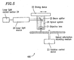
- FIG. 5 is a schematic view of a recording and reproduction apparatus 400 for an optical information recording medium according to the present invention.
- the recording and reproduction apparatus 400 includes a laser light source 20 for emitting laser light, an optical system 26 for collecting the laser light emitted by the laser light source on an optical information recording medium, and a laser light control section 24 for controlling the laser light source.
- the optical system 26 includes an objective lens 21 and a beam splitter 25 .
- Information represented by a signal is recorded on the optical information recording medium, and reproduced and erased from the optical information recording medium are performed using the following elements: an optical head (not shown) having the laser light source 20 and the objective lens 21 mounted thereon, a driving device 22 for guiding the laser light to a prescribed irradiation position, a tracking control device (not shown) and a focusing control device (not shown) for controlling the tracking direction and the position of the light in a direction perpendicular to the surface of the optical information recording medium respectively, a laser light control section 24 for controlling laser power, and a rotation control device 23 for rotating the optical information recording medium.
- the optical information recording medium is rotated by the rotation control device 23 , and the laser light is collected by the optical system 26 to form a small spot so that the optical information recording medium is irradiated with laser light.
- P 1 is the power level of the laser light which can reversibly change a local portion of the recording layer of the optical information recording medium from a second state (for example, a crystalline state) to a first state (for example, an amorphous state)
- P 2 is the power level of the laser light which can reversibly change a local portion of the recording layer of the optical information recording medium from the first state (for example, an amorphous state) to the second state (for example, a crystalline state).
- the optical information recording medium is irradiated with laser light of the power level of P 3 .
- P 3 does not change the optical characteristics (for example, the reflectance) of the optical information recording medium, but provides a sufficient amount of reflected light for reproducing the recorded information.
- P 3 is lower than P 1 and also P 2 .
- ⁇ 1 is the phase of the light reflected by a portion of a land which is in the first state (for example, in an amorphous state having a low reflectance)
- ⁇ 2 is the phase of the light reflected by a portion of the land which is in the second state (for example, in a crystalline state having a high reflectance).
- the track pitch is preferably equal to or less than 0.40 ⁇ m, and more preferably equal to or less than 0.33 ⁇ m.
- the width of a formed recording mark is w and the pitch of the lands is Tp
- the relationship of Tp/4 ⁇ w ⁇ Tp/2 is preferably fulfilled, for the following reasons.
- the mark width w is equal to or less than Tp/4, it is difficult to obtain a large signal amplitude.
- w is equal to or greater than Tp/2, recording is also performed in the outside of the intended land. Therefore, in the case where the above-mentioned relationship is not fulfilled, even when recording is intended to be performed only in the lands, the problem of adjacent erasing occurs.
- the thickness of the first substrate is equal to or less than 0.4 mm, and thickness of the second substrate is equal to or greater than 0.4 mm.
- the numerical aperture (NA) for the laser light is preferably equal to or greater than 0.70. With such conditions, the effects of the present invention are more noticeably provided since higher density recording is possible.
- the wavelength of the laser light is preferably equal to or less than 450 nm. With such conditions, the effects of the present invention are more noticeably provided since higher density recording is possible.
- the first substrate 1 and the second substrate 2 were each formed of a polycarbonate resin disc having a diameter of 120 mm.
- the first substrate 1 had a thickness of 0.1 mm, and the second substrate 2 had a thickness of 1.1 mm.
- the protective layers 3 and 7 were both formed of a material containing ZnS and 20 mol% of SiO 2 .
- the interface layers 4 and 6 were formed of GeCrN.
- the recording layer 5 was formed of Ge 29 Sb 15 Te 54 N 2 .
- the reflective layer 8 was formed of an AgPdCu alloy.
- the protective layers 3 and 7 had a thickness of 56 nm and a thickness of 11 nm respectively.
- the interface layers 4 and 6 each had a thickness of 5 nm.
- the recording layer 5 had a thickness of 10 nm.
- the reflective layer 8 had a thickness of 80 nm.
- the phase difference between a recorded portion and an unrecorded portion was obtained by optical calculation.
- the guide groove for laser light was formed in the second substrate 2 .
- the depth of the guide groove was 35 nm, and the track pitch was 0.37 ⁇ m.
- the recording layer 5 was produced by supplying a mixing gas containing Ar and 2.5% of nitrogen so that the total pressure would be 0.13 Pa, and then by supplying the negative electrode with a power of DC1.27 W/cm 2 .
- the protective layers 3 and 7 were produced by supplying a mixing gas containing Ar and 1.0% of oxygen so that the total pressure would be 0.13 Pa and supplying the negative electrode with a power of RF5.10 W/cm 2 .
- the reflective layer 8 was produced by supplying Ar gas so that the total pressure would be 0.26 Pa and supplying a power of DC4.45 W/cm 2 .
- the interface layers 4 and 6 were each produced using GeCr as a target and a mixing gas of Ar and nitrogen as sputtering gas.
- the sputtering gas pressure was 1.33 Pa
- the nitrogen pressure in the sputtering gas was 40%
- the sputtering power density was RF6.37 W/cm 2 .
- a medium produced by the above-described method will be referred to as medium (1).
- the characteristics of the disc were evaluated regarding the C/N ratio of the signal and the adjacent erasing characteristic.
- the C/N ratio was evaluated by recording a 3T mark (mark length: 0.185 ⁇ m) on a land with an appropriate laser power using a (8-16) modulation system and then measuring the C/N ratio of the signal obtained from the 3T mark. Adjacent erasing was evaluated as follows.
- Ten 3T marks were recorded in the track of a land with an appropriate laser power and the signal amplitude was measured. Then, fifty 3T marks and fifty 11T marks were recorded alternately (100 marks in total) in the tracks of two lands adjacent to the first land. The disc was then scanned by laser light for erasing, so as to erase all marks in the tracks of the two lands. Then, the signal amplitude corresponding to the 3T mark in the track of the first, intermediate land was again measured. The difference between the signal amplitude before and the signal amplitude after the erasing operation (i.e., reduction in the signal amplitude by the erasing operation) was obtained as an amount of adjacent erasing.
- a medium having an identical structure to that of medium (1) except that the track pitch was twice that of medium (1) as shown in Figure 2(a) was produced.
- This medium will be referred to as medium (2).
- the disc characteristics of medium (2) were evaluated regarding the C/N ratio and the adjacent erasing characteristic.
- the C/N ratio was evaluated in a similar manner to medium (1).
- Adjacent erasing was evaluated as follows. Ten 3T marks were recorded in the track of a land with an appropriate laser power and the signal amplitude was measured. Then, fifty 3T marks and fifty 11T marks were recorded alternately (100 marks in total) in the tracks of two grooves adjacent to the land.
- the disc was then scanned by laser light for erasing, so as to erase all marks in the tracks of the two grooves. Then, the signal amplitude corresponding to the 3T mark in the track of the intermediate land was again measured. The difference between the signal amplitude before and the signal amplitude after the erasing operation (i.e., reduction in the signal amplitude by the erasing operation) was obtained as an amount of adjacent erasing. Namely, signals were recorded such that medium (1) and medium (2) had an equal recording capacity.
- medium (3) a medium having an identical structure to that of medium (1) except that information was recorded only in grooves was produced. This medium will be referred to as medium (3).
- Table 1 shows the evaluation results of medium (1), medium (2) and medium (3).
- ⁇ means greater than or equal to 50 dB
- ⁇ means greater than or equal to 48 dB and less than 50 dB
- X means less than 48 dB.
- Adjacent erasing was evaluated in terms of reduction in the signal amplitude.
- ⁇ means less than or equal to 1 dB
- ⁇ means greater than 1 dB and less than or equal to 3 dB
- X means greater than 3 dB.
- medium (1) is satisfactory both in the C/N ratio and the adjacent erasing characteristic.
- Medium (2) is satisfactory in the C/N ratio but causes adjacent erasing.
- Medium (3) is not large in the C/N ratio and not satisfactory in the adjacent erasing characteristic.
- Medium (1) has information recorded only in the lands. Therefore, a satisfactory adjacent erasing characteristic is obtained by the influence of heat being shielded.
- the effect of reducing adjacent erasing is slightly inferior to medium (1).
- the C/N ratio of medium (3) is slightly lower because the layer structure is advantageous to land recording. From the above results, a high C/N ratio and a satisfactory adjacent erasing characteristic can both be obtained by having a layer structure advantageous to land recording and recording information only in the lands.
- media (4), (5), (6), (7), (8), and (9) having the same structure as that of medium (1) except that the thickness of the recording layer 5 was respectively 5.0 nm, 8.0 nm, 9.0 nm, 12.0 nm, 14.0 nm and 16.0 nm.
- the phase difference of each of these media was calculated in a similar manner to that of medium (1).
- the disc characteristics were evaluated in a similar manner to medium (1). The results are shown in Table 2.
- media (4) through (7) are satisfactory both in the C/N ratio and the adjacent erasing characteristic as with medium (1). This is due to the phase differences of these media fulfilling the range of 0.10 ⁇ to 0.50 ⁇ , which is advantageous to land recording.
- Media (8) and (9) having phase differences out of the above-mentioned range, do not provide a high C/N ratio in the lands.
- Media (8) and (9) are also inferior in adjacent erasing characteristic, since the recording layer 5 is relatively thick and thus thermal conduction is easily caused in the recording layer 5 .
- the phase difference can be within the range of 0 to ⁇ by adjusting the thickness of each of the protective layers 3 and 7 . Further, the phase difference can be within a more precise range of, for example, 0.10 ⁇ to 0.50 ⁇ . Especially when the protective layer 7 is relatively thick, the above-mentioned range can be fulfilled easily.
- Such media are slightly inferior to the media including a recording layer 5 having a thickness of less than or equal to 12 nm in terms of the adjacent erasing characteristic, but can provide a high C/N ratio when land recording is performed. Therefore, these media can be adopted.
- the present invention provides an optical information recording medium including a first substrate; a second substrate; and a recording layer formed between the first substrate and the second substrate.
- the optical information recording medium includes lands and grooves, and a distance between a light source of laser light irradiating the optical information recording medium and the lands is larger than a distance between the light source and the grooves.
- the lands are formed in the optical information recording medium at a pitch of less than or equal to 0.40 ⁇ m. Each land is either in a first state having a first reflectance or in a second state having a second reflectance lower than the first reflectance, and the first state and the second state are reversibly changeable by the irradiation of the laser light.
- ⁇ 1 - ⁇ 2 which is a difference between ⁇ 1 and ⁇ 2 , fulfills 2n ⁇ ⁇ ⁇ 1 - ⁇ 2 ⁇ ⁇ + 2n ⁇ (n is an arbitrary integer) where ⁇ 1 is a phase of light reflected by a portion of the land which is in the first state and ⁇ 2 is a phase of light reflected by a portion of the land which is in a second state. Due to the above-described structure, the optical information recording medium prevents adjacent erasing and provides a sufficient C/N ratio even when high density recording is performed. A method for performing information recording, erasing and reproduction using such an optical information recording medium; and an apparatus for performing information recording on, erasing from and reproduction from such optical information recording medium are also provided.
Landscapes
- Optical Recording Or Reproduction (AREA)
- Optical Record Carriers And Manufacture Thereof (AREA)
Abstract
Description
= |RH1exp(iA) + RH2|2 - |RL1exp(iA) + RH2exp (iΔ)|2
= (RH1 2 - RL12) + 2RH2(RH1COSA -RL1COS(A - Δ))
= (RH1 2 - RL12) + 2RH2(RH1COSA -RL1COS(A + Δ))

| Medium number | Recording system | C/N ratio | Adjacent erasing |
| (1) | Land recording | ○ | ○ |
| (2) | Land-groove recording | ○ | X |
| (3) | Groove recording | Δ | Δ |
| Medium number | Recording layer thickness (nm) | Calculated phase difference (rad) | C/N ratio | Adjacent erasing |
| (4) | 5.0 | 0.11π | ○ | ○ |
| (5) | 8.0 | 0.20π | ○ | ○ |
| (6) | 9.0 | 0.18π | ○ | ○ |
| (7) | 12.0 | 0.10π | ○ | ○ |
| (8) | 14.0 | -0.05n | Δ | Δ |
| (9) | 16.0 | -0.12π | X | Δ |
Claims (16)
- An optical information recording medium, comprising:a first substrate; a second substrate; and a recording layer formed between the first substrate and the second substrate, wherein:the optical information recording medium includes lands and grooves, and a distance between a light source of laser light irradiating the optical information recording medium and the lands is larger than a distance between the light source and the grooves,the lands are formed in the optical information recording medium at a pitch of less than or equal to 0.40 µm,each land is either in a first state having a first reflectance or in a second state having a second reflectance lower than the first reflectance, and the first state and the second state are reversibly changeable by the irradiation of the laser light, andwhen a land is irradiated with laser light for reproduction, 1 - 2, which is a difference between 1 and 2, fulfills 2nπ≤ 1 - 2 ≤ π + 2nπ (n is an arbitrary integer) where 1 is a phase of light reflected by a portion of the land which is in the first state and 2 is a phase of light reflected by a portion of the land which is in the second state.
- An optical information recording medium according to claim 1, wherein when a land is irradiated with the laser light for reproduction, 1 - 2, which is a difference between 1 and 2, fulfills 0.1nπ + 2nπ ≤ 1 - 2 ≤ 0.5π + 2nπ (n is an arbitrary integer) where 1 is a phase of light reflected by a portion of the lands which is in the first state and 2 is a phase of light reflected by a portion of the lands which is in the second state.
- An optical information recording medium according to claim 1, wherein the first substrate has a thickness of greater than or equal to 0.01 mm and less than or equal to 0.4 mm, and the second substrate has a thickness of greater than or equal to 0.4 mm.
- An optical information recording medium according to claim 1, further comprising a protective layer formed between the first substrate and the recording layer, and the protective layer has a thickness d1 fulfilling 0.1λ/n2 + nλ/(2 × n2) < d1 < 0.4λ/n2 + nλ/(2 x n2) (n is an arbitrary integer), where λ is a wavelength of the laser light and n2 is a refractive index of the protective layer.
- An optical information recording medium according to claim 1, wherein the recording layer has a thickness greater than or equal to 1 nm and less than or equal to 12 nm.
- An optical information recording medium according to claim 1, further comprising a guide groove for the laser light in a surface of at least one of the first substrate and the second substrate facing the recording layer, and the guide groove has a depth d2 fulfilling λ/20n1 ≤ d2 ≤ λ/8n1, where λ is a wavelength of the laser light and n1 is a refractive index of the substrate on which the laser light is incident first.
- An optical information recording medium according to claim 1, wherein the recording layer includes at least one of Sb and Te.
- An optical information recording medium according to claim 1, wherein at least two recording layers are included.
- An optical information recording medium according to claim 6, wherein the guide grooves are formed at a pitch of less than or equal to 0.40 µm.
- An optical information recording medium according to claim 1, which fulfills Tp/4 < w < Tp/2 where w is a width of a recording mark formed on the lands by the irradiation of the laser light and Tp is the pitch of the lands.
- A method for recording information on, and erasing and reproducing information from an optical information recording medium comprising a first substrate; a second substrate; and a recording layer formed between the first substrate and the second substrate,
wherein:when a land is irradiated with laser light for reproduction, 1 - 2, which is a difference between 1 and 2, fulfills 2nπ ≤ 1- 2 ≤ π + 2nπ (n is an arbitrary integer) where 1 is a phase of light reflected by a portion of the land which is in the first state and 2 is a phase of light reflected by a portion of the land which is in the second state,the optical information recording medium includes lands and grooves, and a distance between a light source of laser light irradiating the optical information recording medium and the lands is larger than a distance between the light source and the grooves,the lands are formed in the optical information recording medium at a pitch of less than or equal to 0.40 µm,each land is either in a first state having a first reflectance or in a second state having a second reflectance lower than the first reflectance, and the first state and the second state are reversibly changeable by the irradiation of the laser light, and
the method comprising the steps of:wherein:modulating a power level of the laser light between P1 and P2 to record the information in the land or erase the information from the land; andirradiating the land with laser light for reproduction having a power level of P3 to reproduce information recorded in the land,P1 is a power level of the laser light which can change the land from the second state to the first state by the irradiation of the laser light, P2 is a power level of the laser light which can change the land from the first state to the second state by the irradiation of the laser light, and P3 is power level of the laser light which does not change the reflectance of the land but provides a sufficient amount of reflected light for reproducing the recorded information by the irradiation of the laser light, P3 being lower than P1 and P2 - A method for recording information on, and erasing and reproducing information from an optical information recording medium according to claim 11, wherein the first substrate has a thickness of less than or equal to 0.4 mm, the second substrate has a thickness of greater than or equal to 0.4 mm, and the laser light is obtained by a numerical aperture of greater than or equal to 0.70.
- A method for recording information on, and erasing and reproducing information from an optical information recording medium according to claim 11, wherein the laser light has a wavelength of less than or equal to 450 nm.
- An apparatus for recording information on, and erasing and reproduce information from an optical information recording medium, the apparatus comprising: a light source for emitting laser light; an optical system for collecting the laser light emitted by the laser light source on the optical information recording medium; and a laser light control section for controlling the laser light source,
wherein:when a land is irradiated with laser light for reproduction, 1 - 2, which is a difference between 1 and 2, fulfills 2nπ ≤ 1- 2≤ π + 2nπ (n is an arbitrary integer) where 1 is a phase of light reflected by a portion of the land which is in the first state and 2 is a phase of light reflected by a portion of the land which is in the second state,the optical information recording medium includes a first substrate; a second substrate; and a recording layer formed between the first substrate and the second substrate,the optical information recording medium includes lands and grooves, and a distance between a light source of laser light irradiating the optical information recording medium and the lands is larger than a distance between the light source and the grooves,the lands are formed in the optical information recording medium at a pitch of less than or equal to 0.40 µm,each land is either in a first state having a first reflectance or in a second state having a second reflectance lower than the first reflectance, and the first state and the second state are reversibly changeable by the irradiation of the laser light, and
wherein:for recording or erasing the information, the laser control section controls the laser light source so as to modulate a power level of the laser light collected on the optical information recording medium by the optical system between P1 and P2,for reproducing the information, the laser control section controls the laser light source so that a power level of the laser light collected on the optical information recording medium by the optical system is P3, andP1 is a power level of the laser light which can change the land from the second state to the first state by the irradiation of the laser light, P2 is a power level of the laser light which can change the land from the first state to the second state by the irradiation of the laser light, and P3 is power level of the laser light which does not change the reflectance of the land but provides a sufficient amount of reflected light for reproducing the recorded information by the irradiation of the laser light, P3 being lower than P1 and P2. - An apparatus for recording information on, and erasing and reproduce information from an optical information recording medium according to claim 14, wherein the first substrate has a thickness of less than or equal to 0.4 mm, the second substrate has a thickness of greater than or equal to 0.4 mm, and the laser light is obtained by a numerical aperture of greater than or equal to 0.70.
- An apparatus for recording information on, and erasing and reproduce information from an optical information recording medium according to claim 14, wherein the laser light has a wavelength of less than or equal to 450 nm.
Applications Claiming Priority (3)
| Application Number | Priority Date | Filing Date | Title |
|---|---|---|---|
| JP2000247325 | 2000-08-17 | ||
| JP2000247325 | 2000-08-17 | ||
| PCT/JP2001/006886 WO2002015175A1 (en) | 2000-08-17 | 2001-08-09 | Optical information recording medium and recording/reproducing method therefor |
Publications (2)
| Publication Number | Publication Date |
|---|---|
| EP1318506A1 true EP1318506A1 (en) | 2003-06-11 |
| EP1318506A4 EP1318506A4 (en) | 2008-02-20 |
Family
ID=18737443
Family Applications (1)
| Application Number | Title | Priority Date | Filing Date |
|---|---|---|---|
| EP01955644A Withdrawn EP1318506A4 (en) | 2000-08-17 | 2001-08-09 | OPTICAL INFORMATION RECORDING MEDIUM AND ASSOCIATED RECORDING / READING METHOD |
Country Status (6)
| Country | Link |
|---|---|
| US (1) | US20030133395A1 (en) |
| EP (1) | EP1318506A4 (en) |
| CN (1) | CN1447967A (en) |
| AU (1) | AU2001277745A1 (en) |
| TW (1) | TWI266298B (en) |
| WO (1) | WO2002015175A1 (en) |
Cited By (1)
| Publication number | Priority date | Publication date | Assignee | Title |
|---|---|---|---|---|
| EP1343154A3 (en) * | 2002-03-05 | 2004-08-04 | Mitsubishi Chemical Corporation | Phase-change recording material used for an information recording medium and an information recording medium employing it |
Families Citing this family (5)
| Publication number | Priority date | Publication date | Assignee | Title |
|---|---|---|---|---|
| EP1347448B1 (en) | 2002-03-22 | 2005-11-23 | Ricoh Company, Ltd. | Optical recording medium and optical recording process using the same |
| US20050068883A1 (en) * | 2003-09-30 | 2005-03-31 | Pioneer Corporation | Optical recording medium and method for production of optical recording medium |
| JP2005115996A (en) * | 2003-10-03 | 2005-04-28 | Pioneer Electronic Corp | Optical recording medium and its manufacturing method |
| JP2006044241A (en) * | 2004-06-30 | 2006-02-16 | Ricoh Co Ltd | Optical recording medium, recording / reproducing method, and optical recording apparatus |
| TWI279795B (en) * | 2005-05-18 | 2007-04-21 | Lite On It Corp | Optical storage medium for use in optical near-field reading apparatus |
Family Cites Families (17)
| Publication number | Priority date | Publication date | Assignee | Title |
|---|---|---|---|---|
| JP3284744B2 (en) * | 1994-04-20 | 2002-05-20 | 松下電器産業株式会社 | Optical information recording medium |
| JPH0883426A (en) * | 1994-09-09 | 1996-03-26 | Matsushita Electric Ind Co Ltd | Optical information recording method and optical information recording medium |
| EP1189212A3 (en) * | 1995-03-28 | 2003-09-17 | Toray Industries, Inc. | Optical recording media and a method for recording on the optical recording media |
| JP3645020B2 (en) * | 1995-12-12 | 2005-05-11 | 富士通株式会社 | Optical information detector |
| JP3138661B2 (en) * | 1996-10-24 | 2001-02-26 | 日本電気株式会社 | Phase change optical disk |
| US5889756A (en) * | 1996-07-25 | 1999-03-30 | Kabushiki Kaisha Toshiba | Phase change optical recording medium |
| EP1146509B1 (en) * | 1997-03-27 | 2005-03-16 | Mitsubishi Chemical Corporation | Optical information recording medium |
| US6564009B2 (en) * | 1997-05-19 | 2003-05-13 | Sony Corporation | Apparatus for recording and/or reproducing data onto and/or from an optical disk and method thereof |
| JP3159374B2 (en) * | 1997-06-03 | 2001-04-23 | 日本電気株式会社 | Optical information recording medium |
| US6477135B1 (en) * | 1998-03-26 | 2002-11-05 | Matsushita Electric Industrial Co., Ltd. | Optical information recording medium and method for recording and reproduction information thereon |
| JP3090118B2 (en) * | 1998-05-08 | 2000-09-18 | 日本電気株式会社 | Optical information recording medium |
| JP2000011453A (en) * | 1998-06-29 | 2000-01-14 | Sony Corp | Optical recording medium and optical recording / reproducing device |
| EP0997899B1 (en) * | 1998-09-22 | 2005-05-04 | Matsushita Electric Industrial Co., Ltd. | Optical disk, method for reproducing additional information from optical disk, reproducing apparatus for optical disk, and recording and reproducing apparatus for optical disk |
| US6636477B1 (en) * | 1998-10-07 | 2003-10-21 | Hitachi, Ltd. | Information recording medium and information recording device |
| WO2001004888A1 (en) * | 1999-07-12 | 2001-01-18 | Matsushita Electric Industrial Co., Ltd. | Optical information recording medium and method for initializing the same |
| US6449241B1 (en) * | 1999-11-03 | 2002-09-10 | Samsung Electronics Co., Ltd. | Optical disk |
| CN1201309C (en) * | 2000-06-16 | 2005-05-11 | 三菱化学株式会社 | Optical information recording medium |
-
2001
- 2001-08-09 AU AU2001277745A patent/AU2001277745A1/en not_active Abandoned
- 2001-08-09 EP EP01955644A patent/EP1318506A4/en not_active Withdrawn
- 2001-08-09 US US10/312,016 patent/US20030133395A1/en not_active Abandoned
- 2001-08-09 WO PCT/JP2001/006886 patent/WO2002015175A1/en not_active Ceased
- 2001-08-09 CN CN01814228.1A patent/CN1447967A/en active Pending
- 2001-08-14 TW TW090119926A patent/TWI266298B/en not_active IP Right Cessation
Cited By (1)
| Publication number | Priority date | Publication date | Assignee | Title |
|---|---|---|---|---|
| EP1343154A3 (en) * | 2002-03-05 | 2004-08-04 | Mitsubishi Chemical Corporation | Phase-change recording material used for an information recording medium and an information recording medium employing it |
Also Published As
| Publication number | Publication date |
|---|---|
| EP1318506A4 (en) | 2008-02-20 |
| CN1447967A (en) | 2003-10-08 |
| US20030133395A1 (en) | 2003-07-17 |
| WO2002015175A1 (en) | 2002-02-21 |
| TWI266298B (en) | 2006-11-11 |
| AU2001277745A1 (en) | 2002-02-25 |
Similar Documents
| Publication | Publication Date | Title |
|---|---|---|
| JP2697555B2 (en) | Optical information recording medium | |
| US7012878B2 (en) | Optical recording medium and optical recording process using the same | |
| EP1329878A1 (en) | Optical information recording medium and method of reproducing the record | |
| EP0957477A2 (en) | Optical information recording medium, recording and reproducing method therefor and optical information recording and reproduction apparatus | |
| JP4680465B2 (en) | Optical information recording medium, recording / reproducing method thereof, and optical information recording / reproducing system using the same | |
| JPH081707B2 (en) | Optical information recording medium | |
| JP4339999B2 (en) | Optical information recording medium, manufacturing method thereof, recording / reproducing method, and recording / reproducing apparatus | |
| KR20000062409A (en) | Recording and reproducing method for optical information recording medium and optical information recording medium | |
| JP3087433B2 (en) | Optical information recording medium and structure design method thereof | |
| EP1318506A1 (en) | Optical information recording medium and recording/reproducing method therefor | |
| JP3012734B2 (en) | Optical information recording medium and structure design method thereof | |
| US7431973B2 (en) | Optical information recording medium, and manufacturing method, recording method, and recording apparatus thereof | |
| JP3344198B2 (en) | Optical recording medium and recording / reproducing method | |
| JP3625541B2 (en) | Optical recording medium and recording / reproducing method | |
| JP2002190139A (en) | Optical storage medium | |
| JP3087454B2 (en) | Optical information recording medium and structure design method thereof | |
| JPH11115315A (en) | Optical information recording medium, manufacturing method thereof, and information recording / reproducing method using this medium | |
| US20070065759A1 (en) | Optical information recording medium and method for manufacturing the same | |
| JP2001028148A (en) | Optical information recording medium, manufacturing method thereof, recording / reproducing method, and recording / reproducing apparatus | |
| JP2004005920A (en) | Phase change type information recording medium | |
| JP4468951B2 (en) | Optical information recording medium and optical information recording / reproducing system | |
| JP4542922B2 (en) | Optical information recording medium and manufacturing method thereof | |
| JP2004311011A (en) | Optical information recording medium and manufacturing method thereof, information recording method and recording apparatus using this medium | |
| JP2001344823A (en) | Optical information recording medium, its manufacturing method, and its recording / reproducing method | |
| JP4111164B2 (en) | Optical recording medium and recording / reproducing method |
Legal Events
| Date | Code | Title | Description |
|---|---|---|---|
| PUAI | Public reference made under article 153(3) epc to a published international application that has entered the european phase |
Free format text: ORIGINAL CODE: 0009012 |
|
| 17P | Request for examination filed |
Effective date: 20030131 |
|
| AK | Designated contracting states |
Designated state(s): AT BE CH CY DE DK ES FI FR GB GR IE IT LI LU MC NL PT SE TR |
|
| AX | Request for extension of the european patent |
Extension state: AL LT LV MK RO SI |
|
| RBV | Designated contracting states (corrected) |
Designated state(s): DE FR GB |
|
| A4 | Supplementary search report drawn up and despatched |
Effective date: 20080121 |
|
| RIC1 | Information provided on ipc code assigned before grant |
Ipc: G11B 7/007 20060101ALI20080115BHEP Ipc: G11B 7/24 20060101ALI20080115BHEP Ipc: G11B 7/013 20060101ALI20080115BHEP Ipc: G11B 7/00 20060101AFI20020226BHEP |
|
| 17Q | First examination report despatched |
Effective date: 20080415 |
|
| RAP1 | Party data changed (applicant data changed or rights of an application transferred) |
Owner name: PANASONIC CORPORATION |
|
| STAA | Information on the status of an ep patent application or granted ep patent |
Free format text: STATUS: THE APPLICATION IS DEEMED TO BE WITHDRAWN |
|
| 18D | Application deemed to be withdrawn |
Effective date: 20080826 |