EP1318500A1 - Anordnung zur Ansteuerung einer Anzeigevorrichtung - Google Patents
Anordnung zur Ansteuerung einer Anzeigevorrichtung Download PDFInfo
- Publication number
- EP1318500A1 EP1318500A1 EP02102691A EP02102691A EP1318500A1 EP 1318500 A1 EP1318500 A1 EP 1318500A1 EP 02102691 A EP02102691 A EP 02102691A EP 02102691 A EP02102691 A EP 02102691A EP 1318500 A1 EP1318500 A1 EP 1318500A1
- Authority
- EP
- European Patent Office
- Prior art keywords
- display device
- supply
- column
- arrangement
- column output
- Prior art date
- Legal status (The legal status is an assumption and is not a legal conclusion. Google has not performed a legal analysis and makes no representation as to the accuracy of the status listed.)
- Withdrawn
Links
- 239000011159 matrix material Substances 0.000 claims abstract description 19
- 230000003321 amplification Effects 0.000 claims 2
- 238000003199 nucleic acid amplification method Methods 0.000 claims 2
- 238000005516 engineering process Methods 0.000 description 7
- 239000003086 colorant Substances 0.000 description 5
- 238000010586 diagram Methods 0.000 description 2
- 238000005265 energy consumption Methods 0.000 description 2
- 230000003213 activating effect Effects 0.000 description 1
- 238000006243 chemical reaction Methods 0.000 description 1
- 230000000694 effects Effects 0.000 description 1
- 230000005611 electricity Effects 0.000 description 1
- 239000010408 film Substances 0.000 description 1
- 230000006870 function Effects 0.000 description 1
- 239000011521 glass Substances 0.000 description 1
- 230000015654 memory Effects 0.000 description 1
- 239000000203 mixture Substances 0.000 description 1
- 229910052710 silicon Inorganic materials 0.000 description 1
- 239000010703 silicon Substances 0.000 description 1
- 239000010409 thin film Substances 0.000 description 1
Images

Classifications
-
- G—PHYSICS
- G09—EDUCATION; CRYPTOGRAPHY; DISPLAY; ADVERTISING; SEALS
- G09G—ARRANGEMENTS OR CIRCUITS FOR CONTROL OF INDICATING DEVICES USING STATIC MEANS TO PRESENT VARIABLE INFORMATION
- G09G3/00—Control arrangements or circuits, of interest only in connection with visual indicators other than cathode-ray tubes
- G09G3/20—Control arrangements or circuits, of interest only in connection with visual indicators other than cathode-ray tubes for presentation of an assembly of a number of characters, e.g. a page, by composing the assembly by combination of individual elements arranged in a matrix no fixed position being assigned to or needed to be assigned to the individual characters or partial characters
- G09G3/34—Control arrangements or circuits, of interest only in connection with visual indicators other than cathode-ray tubes for presentation of an assembly of a number of characters, e.g. a page, by composing the assembly by combination of individual elements arranged in a matrix no fixed position being assigned to or needed to be assigned to the individual characters or partial characters by control of light from an independent source
- G09G3/36—Control arrangements or circuits, of interest only in connection with visual indicators other than cathode-ray tubes for presentation of an assembly of a number of characters, e.g. a page, by composing the assembly by combination of individual elements arranged in a matrix no fixed position being assigned to or needed to be assigned to the individual characters or partial characters by control of light from an independent source using liquid crystals
- G09G3/3611—Control of matrices with row and column drivers
- G09G3/3685—Details of drivers for data electrodes
- G09G3/3688—Details of drivers for data electrodes suitable for active matrices only
-
- G—PHYSICS
- G09—EDUCATION; CRYPTOGRAPHY; DISPLAY; ADVERTISING; SEALS
- G09G—ARRANGEMENTS OR CIRCUITS FOR CONTROL OF INDICATING DEVICES USING STATIC MEANS TO PRESENT VARIABLE INFORMATION
- G09G2310/00—Command of the display device
- G09G2310/02—Addressing, scanning or driving the display screen or processing steps related thereto
- G09G2310/0264—Details of driving circuits
- G09G2310/027—Details of drivers for data electrodes, the drivers handling digital grey scale data, e.g. use of D/A converters
-
- G—PHYSICS
- G09—EDUCATION; CRYPTOGRAPHY; DISPLAY; ADVERTISING; SEALS
- G09G—ARRANGEMENTS OR CIRCUITS FOR CONTROL OF INDICATING DEVICES USING STATIC MEANS TO PRESENT VARIABLE INFORMATION
- G09G2330/00—Aspects of power supply; Aspects of display protection and defect management
- G09G2330/02—Details of power systems and of start or stop of display operation
- G09G2330/021—Power management, e.g. power saving
-
- G—PHYSICS
- G09—EDUCATION; CRYPTOGRAPHY; DISPLAY; ADVERTISING; SEALS
- G09G—ARRANGEMENTS OR CIRCUITS FOR CONTROL OF INDICATING DEVICES USING STATIC MEANS TO PRESENT VARIABLE INFORMATION
- G09G2330/00—Aspects of power supply; Aspects of display protection and defect management
- G09G2330/02—Details of power systems and of start or stop of display operation
- G09G2330/021—Power management, e.g. power saving
- G09G2330/022—Power management, e.g. power saving in absence of operation, e.g. no data being entered during a predetermined time
-
- G—PHYSICS
- G09—EDUCATION; CRYPTOGRAPHY; DISPLAY; ADVERTISING; SEALS
- G09G—ARRANGEMENTS OR CIRCUITS FOR CONTROL OF INDICATING DEVICES USING STATIC MEANS TO PRESENT VARIABLE INFORMATION
- G09G3/00—Control arrangements or circuits, of interest only in connection with visual indicators other than cathode-ray tubes
- G09G3/20—Control arrangements or circuits, of interest only in connection with visual indicators other than cathode-ray tubes for presentation of an assembly of a number of characters, e.g. a page, by composing the assembly by combination of individual elements arranged in a matrix no fixed position being assigned to or needed to be assigned to the individual characters or partial characters
- G09G3/34—Control arrangements or circuits, of interest only in connection with visual indicators other than cathode-ray tubes for presentation of an assembly of a number of characters, e.g. a page, by composing the assembly by combination of individual elements arranged in a matrix no fixed position being assigned to or needed to be assigned to the individual characters or partial characters by control of light from an independent source
- G09G3/36—Control arrangements or circuits, of interest only in connection with visual indicators other than cathode-ray tubes for presentation of an assembly of a number of characters, e.g. a page, by composing the assembly by combination of individual elements arranged in a matrix no fixed position being assigned to or needed to be assigned to the individual characters or partial characters by control of light from an independent source using liquid crystals
- G09G3/3611—Control of matrices with row and column drivers
- G09G3/3696—Generation of voltages supplied to electrode drivers
Definitions
- the invention relates to an arrangement for controlling a display device with columns and rows where the columns of the display device are different Voltage values depending on the data to be displayed are supplied. Further The invention relates to a display device with an arrangement for Control.
- the display technology will play an increasingly important role in the next few years Information and communication technology too.
- the display device As an interface between people and In the digital world, the display device is of central importance for acceptance modern information systems.
- portable devices such. B. notebooks, Phones, digital cameras and personal digital assistants are without the use of Displays cannot be realized.
- the active matrix displays have become very important since fast image changes using this technology, e.g. the representation of a mouse pointer or film can be realized.
- the Pixels or pixels actively controlled.
- TFT-LCD thin film transistors
- Transistors allow this Silicon, which are integrated directly into each pixel, storing the image signals in the Pixel.
- To different grayscale or colors when displaying it is necessary to use the displays or indicators with correspondingly different voltages from a wide voltage range head for. For this control of the display device or displays Driver circuits used.
- TFT displays typically consist of a glass with after externally routed connections to the driver circuits or arrangements for Control are connected. These driver circuits convert the image signals or Data to be shown on a display in the corresponding Voltage values around. The image information is in memories as digital signals or Data saved. These digital signals must be converted into analog signals be so that by means of an analog voltage a corresponding light intensity for Can be brought. The digital-to-analog converters required for this conversion need to convert digital signals into voltages that span a range of go less than 20 mV to more than 10 V.
- Energy consumption is a particularly important criterion in portable devices because the lifespan of the device's battery and thus the service life of the device depends.
- the object of the invention is therefore an arrangement for controlling a display device specify where energy consumption is reduced.
- This object is achieved with an arrangement for controlling a display device solved, with columns and rows, in which the columns of the display device tensions in Dependency of the data to be displayed can be supplied with two supply voltage lines, which carry a maximum and minimum column tension, and at which between to the supply voltage lines at least one voltage divider unit Generation of partial voltage values is arranged, and a supply of the partial voltage values to column output circuits is provided, with a column output circuit has at least one switching matrix and / or amplifier unit and the switch matrix and / or amplifier units from the supply voltage lines by means of switches can be switched off and one of the other switches Supply voltages can be switched to a column output.
- the invention is based on the idea that the full scope of services or scope of display a portable electronic device is usually only needed for a short time. In the rest of the time, simplified ads are usually sufficient. To be used a lot Partial mode or standby mode also right in terms of energy saving can be exploited by switching off the modules that are not required in standby mode significant energy savings can be achieved.
- the switchable column output circuits according to the invention make it possible to switch off the amplifier units and the supply voltages directly to the To put column outputs of the driver circuit.
- realizations according to the state of the The technology is in the switching mode of the column output circuits much more complex to control the amplifier so that the supply voltages at the output of the amplifier / column output.
- TFT transistors for each pixel in a color active matrix display assigned to switch the corresponding colors red, green and blue. These TFT transistors according to the data to be displayed with one of the two Supply voltages controlled to either be switched on or off. This makes it possible to use only two different voltages, namely the both supply voltages Vcolmax or Vcolmin, 8 different colors produce.
- a display device with an arrangement for Control of the display device with two supply voltage lines, one lead maximum and minimum column voltage, and at that between the supply voltage lines at least one voltage divider unit for generating partial voltage values is arranged, and a supply of the partial voltage values Column output circuits are provided, with a column output circuit has at least one switching matrix and / or amplifier unit and the switch Switching matrix and / or amplifier units from the supply voltage lines can be switched off and one of the supply voltages to a column output by means of a switch are switchable.
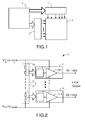
- FIG. 1 shows a block diagram for controlling a display 2.
- the Information to be displayed is stored in unit 4 or is generated by it generated.
- the display 2 has at least one column driver 1 and one row driver 2 assigned.
- Each pixel of the display is at least one TFT transistor, not shown assigned.
- the transistors in a row are activated in sequence. By applying a corresponding column voltage to the TFT transistor, the accordingly activated pixel on the gray level corresponding to the column voltage.
- FIG. 2 shows an arrangement 3 for controlling a display device according to the State of the art.
- This arrangement 3 has a voltage divider unit 33 which partial voltages depending on the data or image information to be displayed generated, which are each supplied to the column output circuits 3n.
- These column output circuits include a switching matrix 311 and an amplifier 312 Switching matrix 311 forms a digital-to-analog converter in connection with the voltage divider unit 33.
- the amplifiers 312 are connected to the supply voltage Vdd and Vss connected.
- Each column input of the display is a column output circuit assigned. This enables each column of the display to display all possible column voltage values supply. In this example, using the voltage divider unit 33 a total of 64 different partial voltages are generated, which lead to 64 different Column voltage values V0-V63 are amplified.
- the display device is in one Switched to standby mode, all amplifiers 312 and the voltage divider unit are still 33 connected to the supply voltage VDD and VSS. Since it is for the Stand-by mode is not required to generate as many column voltages as in the Normal display mode, the amplifiers 312 are controlled to be the one Supply voltages VDD or VSS supply voltage close to the output. The current consumption for operating the column output circuits and in particular the However, an amplifier is not required because the supply voltages VDD and VSS in the arrangement 3 are present.
- Figure 3 shows an arrangement according to the invention for controlling a display device.
- a voltage divider unit 43 is present in this arrangement 40, and a column output circuit 41 N is also assigned to each column output n.
- the voltage divider unit 43 can be switched off from the supply voltage V DD and V SS by means of a switching unit 15 during the stand-by mode.
- the single amplifier 412 and the switch matrices 411 in the column output circuits 41 N from the supply voltage are separable or disconnectable.
- the switching matrices 411 each form a DA converter with the voltage divider unit 43. It is intended to provide the column output circuits 41 N with switches S1-S5.
- the switches S1-S5 of the column output circuit 41 N are controlled such that the amplifier 412 and the switching matrices 411 are turned off, and thus do not consume any more current.
- the V dd or the V ss voltage is then fed to the column outputs n as the column voltage.
- Switches S1 and S2 are activated, for example, by activating the stand-by mode opened a processor, not shown. This is the respective column output circuit disconnected from the supply voltage and no longer consumes electricity.
- amplifier units 412 can also be switched off internally.
- the Switches S 1 and S2 need not be arranged in every column output circuit. It is sufficient the supply voltage supply for all column output circuits interrupt.
- the switches S3-S5 are controlled by means of simple logic circuits.
- Switch S3 is supplied with the maximum supply voltage when that of the column output circuit assigned column should be switched on in stand-by mode or the Data "111111" are pending.
- the switch S4 is only in normal mode closed, in stand-by mode it is constantly open for all column output circuits. This can be deduced by negating the two switches S5 and S3.
- the amplifiers have switches internally in the output stages, which can be used alternatively or in conjunction with the external switches to switch the V DD or the V SS to the corresponding column output. These internal switches are each connected to V DD or the V SS .
- a table is shown below in which the color mixture for one pixel is illustrated.
- a pixel consists of three sub-pixels with the colors red, green and blue.
- the recognizable color of the pixel on the display device can be varied by applying different column voltages to these three TFT transistors.
- the colors that can be displayed are shown on the display device. red green blue black 0 0 0 0 blue 0 0 1 green 0 1 0 cyan 0 1 1 1 0 1 White 1 1 1
Landscapes
- Engineering & Computer Science (AREA)
- Chemical & Material Sciences (AREA)
- Crystallography & Structural Chemistry (AREA)
- Physics & Mathematics (AREA)
- Computer Hardware Design (AREA)
- General Physics & Mathematics (AREA)
- Theoretical Computer Science (AREA)
- Control Of Indicators Other Than Cathode Ray Tubes (AREA)
- Liquid Crystal Display Device Control (AREA)
- Liquid Crystal (AREA)
Abstract
Description
- Fig. 1:
- Blockschaltbild zur Ansteuerung einer Anzeigeanordnung
- Fig.2:
- Treiberschaltung nach den Stand der Technik
- Fig.3:
- erfindungsgemäße Treiberschaltung mit Spaltenausgangschaltungen
| Rot | Grün | Blau | |
| Schwarz | 0 | 0 | 0 |
| Blau | 0 | 0 | 1 |
| Grün | 0 | 1 | 0 |
| Cyan | 0 | 1 | 1 |
| 1 | 0 | 1 | |
| Weiß | 1 | 1 | 1 |
Claims (8)
- Anordnung (1, 40) zur Ansteuerung einer Anzeigevorrichtung (2) mit Spalten und Zeilen, bei der den Spalten der Anzeigevorrichtung Spannungen in Abhängigkeit darzustellender Daten zuführbar sind,
mit zwei Versorgungsspannungsleitungen, die eine maximale und minimale Spaltenspannung (Vcolmax und Vcolmin) führen, und
bei der zwischen den Versorgungsspannungsleitungen wenigstens eine Spannungsteilereinheit (43) zur Erzeugung von Teilspannungswerten angeordnet ist, und eine Zuführung der Teilspannungswerte zu Spaltenausgangsschaltungen (41N) vorgesehen ist, wobei eine Spaltenausgangsschaltung (41N) wenigstens eine Schaltmatrix- (411) und/oder Verstärkereinheit (412) aufweist und mittels Schalter (S1, S2) die Schaltmatrix-und/oder Verstärkereinheiten von den Versorgungsspannungsleitungen abschaltbar und mittels Schalter (S3-S5) eine der Versorgungsspannungen auf einen Spaltenausgang schaltbar sind. - Anordnung zur Ansteuerung einer Anzeigevorrichtung nach Anspruch 1,
dadurch gekennzeichnet, dass die Anzeigevorrichtung (2) in einem Standby-Mode betreibbar ist, in der vorgesehen ist, den Spalten nur die Versorgungsspannungen (Vcolmax und Vcolmin) zuzuführen und die Spannungsteilereinheit, Schaltmatrix- und Verstärkereinheit von den Versorgungsspannungsleitungen zu entkoppeln. - Anordnung zur Ansteuerung einer Anzeigevorrichtung nach Anspruch 1,
dadurch gekennzeichnet, dass jeder Spalte der Anzeigevorrichtung eine Spaltenausgangsschaltung (41N) zugeordnet ist. - Anordnung zur Ansteuerung einer Anzeigevorrichtung nach Anspruch 1,
dadurch gekennzeichnet, dass eine Schalteinheit (15) zur Entkopplung der Spannungsteilereinheit (43) von den Versorgungsspannungsleitungen vorgesehen ist - Anordnung zur Ansteuerung einer Anzeigevorrichtung nach Anspruch 1,
dadurch gekennzeichnet, dass die Spannungsteilereinheit (15) mehrere in Reihe zwischen die beiden Versorgungsspannungsleitungen geschaltete Widerstandselemente enthält, die mit wenigstens einer Schaltmatrix- gekoppelt sind, die an eine Verstärkereinheit angeschlossen ist. - Anordnung zur Ansteuerung einer Anzeigevorrichtung nach Anspruch 1,
dadurch gekennzeichnet, dass der Verstärkereinheit ein analoger Spannungswert zur Verstärkung zuführbar ist und die Verstärkereinheit an beide Versorgungsspannungsleitungen angeschlossen ist. - Anordnung zur Ansteuerung einer Anzeigevorrichtung nach Anspruch 1,
dadurch gekennzeichnet,
die Verstärkungseinheiten (412) im Stand-By Mode abschaltbar sind und die Versorgungsspannungsleitungen mittels verstärkerinterner Schalter auf den Spaltenausgang schaltbar sind. - Anzeigevorrichtung mit einer Ansteuervorrichtung nach einem der Ansprüche 1 bis 6.
Applications Claiming Priority (2)
| Application Number | Priority Date | Filing Date | Title |
|---|---|---|---|
| DE10160098A DE10160098A1 (de) | 2001-12-07 | 2001-12-07 | Anordnung zur Ansteuerung einer Anzeigevorrichtung |
| DE10160098 | 2001-12-07 |
Publications (1)
| Publication Number | Publication Date |
|---|---|
| EP1318500A1 true EP1318500A1 (de) | 2003-06-11 |
Family
ID=7708338
Family Applications (1)
| Application Number | Title | Priority Date | Filing Date |
|---|---|---|---|
| EP02102691A Withdrawn EP1318500A1 (de) | 2001-12-07 | 2002-12-06 | Anordnung zur Ansteuerung einer Anzeigevorrichtung |
Country Status (5)
| Country | Link |
|---|---|
| US (1) | US7515145B2 (de) |
| EP (1) | EP1318500A1 (de) |
| JP (1) | JP2003208143A (de) |
| CN (1) | CN100407258C (de) |
| DE (1) | DE10160098A1 (de) |
Cited By (2)
| Publication number | Priority date | Publication date | Assignee | Title |
|---|---|---|---|---|
| WO2004075157A1 (en) * | 2003-02-19 | 2004-09-02 | Koninklijke Philips Electronics N. V. | Control method and device for a display device |
| EP1708168A3 (de) * | 2005-03-31 | 2009-07-01 | Himax Technologies, Inc. | Energiesparverfahren für eine Chip-on-Glass-Flüssigkristallanzeige |
Families Citing this family (7)
| Publication number | Priority date | Publication date | Assignee | Title |
|---|---|---|---|---|
| CN100365693C (zh) * | 2003-11-14 | 2008-01-30 | 矽创电子股份有限公司 | 稳压补偿型跟随器 |
| JP2006126471A (ja) * | 2004-10-28 | 2006-05-18 | Nec Micro Systems Ltd | 表示装置の駆動回路および駆動方法 |
| KR20070020778A (ko) * | 2005-08-17 | 2007-02-22 | 삼성전자주식회사 | 액정 표시 장치와 이의 검사 방법 및 이의 리페어 방법 |
| US9478186B2 (en) * | 2010-10-28 | 2016-10-25 | Sharp Kabushiki Kaisha | Display device with idle periods for data signals |
| DE102011088499A1 (de) * | 2011-12-14 | 2013-06-20 | Robert Bosch Gmbh | Schaltungsanordnung zum Einschalten eines elektronischen Gerätes |
| CN103151016B (zh) * | 2013-03-14 | 2015-07-15 | 京东方科技集团股份有限公司 | 一种显示面板维修电路 |
| CN105895041B (zh) * | 2016-06-06 | 2018-08-24 | 深圳市华星光电技术有限公司 | 公共电极驱动模块以及液晶显示面板 |
Citations (6)
| Publication number | Priority date | Publication date | Assignee | Title |
|---|---|---|---|---|
| EP0611144A2 (de) * | 1993-02-09 | 1994-08-17 | Sharp Kabushiki Kaisha | Spannungserzeugungsschaltung, Steuerungsschaltung für gemeinsame Elektrode, Steuerungsschaltung für Signalleitung und Grauskala-Spannungserzeugungsschaltung für Anzeigevorrichtungen |
| US5659371A (en) * | 1995-07-21 | 1997-08-19 | Apple Computer, Inc. | Method and apparatus for power supply startup in video monitors |
| US5751278A (en) * | 1990-08-10 | 1998-05-12 | Sharp Kabushiki Kaisha | Clocking method and apparatus for display device with calculation operation |
| US5805121A (en) * | 1996-07-01 | 1998-09-08 | Motorola, Inc. | Liquid crystal display and turn-off method therefor |
| US6124853A (en) * | 1996-09-03 | 2000-09-26 | Lear Automotive Dearborn, Inc. | Power dissipation control for a visual display screen |
| WO2001048731A1 (en) * | 1999-12-28 | 2001-07-05 | Koninklijke Philips Electronics N.V. | Lcd device |
Family Cites Families (8)
| Publication number | Priority date | Publication date | Assignee | Title |
|---|---|---|---|---|
| US5528256A (en) * | 1994-08-16 | 1996-06-18 | Vivid Semiconductor, Inc. | Power-saving circuit and method for driving liquid crystal display |
| JP3368819B2 (ja) * | 1997-01-16 | 2003-01-20 | 日本電気株式会社 | 液晶駆動回路 |
| WO1998048318A1 (en) * | 1997-04-22 | 1998-10-29 | Matsushita Electric Industrial Co., Ltd. | Drive circuit for active matrix liquid crystal display |
| US5952948A (en) * | 1997-09-24 | 1999-09-14 | Townsend And Townsend And Crew Llp | Low power liquid-crystal display driver |
| US5954820A (en) * | 1997-09-26 | 1999-09-21 | International Business Machines Corporation | Portable computer with adaptive demand-driven power management |
| US6243817B1 (en) * | 1997-12-22 | 2001-06-05 | Compaq Computer Corporation | Device and method for dynamically reducing power consumption within input buffers of a bus interface unit |
| US6118439A (en) * | 1998-02-10 | 2000-09-12 | National Semiconductor Corporation | Low current voltage supply circuit for an LCD driver |
| US6850218B2 (en) * | 2000-12-18 | 2005-02-01 | Brillian Corporation | Frame prewriting in a liquid crystal display |
-
2001
- 2001-12-07 DE DE10160098A patent/DE10160098A1/de not_active Withdrawn
-
2002
- 2002-12-04 CN CN021606285A patent/CN100407258C/zh not_active Expired - Fee Related
- 2002-12-05 US US10/310,729 patent/US7515145B2/en not_active Expired - Fee Related
- 2002-12-06 JP JP2002355570A patent/JP2003208143A/ja active Pending
- 2002-12-06 EP EP02102691A patent/EP1318500A1/de not_active Withdrawn
Patent Citations (6)
| Publication number | Priority date | Publication date | Assignee | Title |
|---|---|---|---|---|
| US5751278A (en) * | 1990-08-10 | 1998-05-12 | Sharp Kabushiki Kaisha | Clocking method and apparatus for display device with calculation operation |
| EP0611144A2 (de) * | 1993-02-09 | 1994-08-17 | Sharp Kabushiki Kaisha | Spannungserzeugungsschaltung, Steuerungsschaltung für gemeinsame Elektrode, Steuerungsschaltung für Signalleitung und Grauskala-Spannungserzeugungsschaltung für Anzeigevorrichtungen |
| US5659371A (en) * | 1995-07-21 | 1997-08-19 | Apple Computer, Inc. | Method and apparatus for power supply startup in video monitors |
| US5805121A (en) * | 1996-07-01 | 1998-09-08 | Motorola, Inc. | Liquid crystal display and turn-off method therefor |
| US6124853A (en) * | 1996-09-03 | 2000-09-26 | Lear Automotive Dearborn, Inc. | Power dissipation control for a visual display screen |
| WO2001048731A1 (en) * | 1999-12-28 | 2001-07-05 | Koninklijke Philips Electronics N.V. | Lcd device |
Cited By (3)
| Publication number | Priority date | Publication date | Assignee | Title |
|---|---|---|---|---|
| WO2004075157A1 (en) * | 2003-02-19 | 2004-09-02 | Koninklijke Philips Electronics N. V. | Control method and device for a display device |
| US7471272B2 (en) | 2003-02-19 | 2008-12-30 | Nxp B.V. | Control method and device for a display device |
| EP1708168A3 (de) * | 2005-03-31 | 2009-07-01 | Himax Technologies, Inc. | Energiesparverfahren für eine Chip-on-Glass-Flüssigkristallanzeige |
Also Published As
| Publication number | Publication date |
|---|---|
| JP2003208143A (ja) | 2003-07-25 |
| DE10160098A1 (de) | 2003-06-18 |
| US7515145B2 (en) | 2009-04-07 |
| US20030112212A1 (en) | 2003-06-19 |
| CN100407258C (zh) | 2008-07-30 |
| CN1423251A (zh) | 2003-06-11 |
Similar Documents
| Publication | Publication Date | Title |
|---|---|---|
| DE60132540T2 (de) | Anzeige, steuerverfahren dafür und tragbares endgerät | |
| DE60104927T2 (de) | Flüssigkristallanzeige mit auf digitalen Daten basierten Graustufen, tragbares Telefon und tragbarer persönlicher Hilfsrechner | |
| DE60313066T2 (de) | Referenzspannungschaltkreis | |
| DE69530060T2 (de) | Energiesparschaltung und steuerverfahren für flüssigkristallanzeige | |
| DE10025252B4 (de) | Verfahren und System zum Ansteuern von Datenleitungen und eine das Verfahren und System verwendende Flüssigkristallanzeigevorrichtung | |
| DE10010955B4 (de) | Verfahren zum Steuern von Flüssigkristallanzeigevorrichtungen | |
| DE69434493T2 (de) | Spannungserzeugungsschaltung, Steuerungsschaltung für gemeinsame Elektrode, Steuerungsschaltung für Signalleitung und Grauskala-Spannungserzeugungsschaltung für Anzeigevorrichtungen | |
| DE60121650T2 (de) | Verfahren und Einrichtung zur Graustufensteuerung von Anzeigetafeln | |
| DE69838277T2 (de) | Schaltung und verfahren zur ansteuerung einer elektrooptischen vorrichtung, elektrooptisches gerät und dieses verwendende elektronische einrichtung | |
| DE60307691T2 (de) | Referenzspannungserzeugungsverfahren und -schaltung, Anzeigesteuerschaltung und Anzeigeeinrichtung mit Gammakorrektur und reduziertem Leistungsverbrauch | |
| JP3779166B2 (ja) | 階調表示用電圧発生装置、及びそれを備えた階調表示装置 | |
| DE102008025915B4 (de) | Video-Displaytreiber mit Daten-Enable-Lernfunktion | |
| EP2564383B1 (de) | Pixelschaltung für ein aktiv-matrix oled-display | |
| DE102004040987B4 (de) | Matrix-Display mit adressierbaren Display-Elementen und Verfahren | |
| DE60111443T2 (de) | Ladungspumpen-Leistungsversorgungsschaltung und Ansteuerschaltung für Anzeigegerät und eine solche Leistungsversorgungsschalutng benutzendes Anzeigegerät | |
| US20090167747A1 (en) | Tft-lcd driver circuit and lcd devices | |
| DE102008025914A1 (de) | Video-Display mit Gamma-Steuerung | |
| DE10303427A1 (de) | Verstärker-Schaltung, Treiber-Schaltung für ein Anzeigegerät , tragbares Telefon und tragbares elektronisches Gerät | |
| DE112018004137T5 (de) | Flüssigkristall-anzeigevorrichtung, bildanzeigesystem und fahrzeug | |
| DE102004057274A1 (de) | Stromverstärkeschaltung mit stabilisierter Ausgangsspannung und Flüssigkristallanzeige, die diese beinhaltet | |
| DE102008025916A1 (de) | Video-Displaytreiber mit Teilspeicher-Steuerung | |
| DE102006058816B4 (de) | Flüssigkristallanzeige | |
| DE102017125320A1 (de) | Datentreiber und Anzeigevorrichtung, die ihn verwendet | |
| KR20030023468A (ko) | 표시 구동 장치 및 그것을 이용하는 액정 표시 장치 | |
| DE10160098A1 (de) | Anordnung zur Ansteuerung einer Anzeigevorrichtung |
Legal Events
| Date | Code | Title | Description |
|---|---|---|---|
| PUAI | Public reference made under article 153(3) epc to a published international application that has entered the european phase |
Free format text: ORIGINAL CODE: 0009012 |
|
| AK | Designated contracting states |
Designated state(s): AT BE BG CH CY CZ DE DK EE ES FI FR GB GR IE IT LI LU MC NL PT SE SI SK TR |
|
| AX | Request for extension of the european patent |
Extension state: AL LT LV MK RO |
|
| 17P | Request for examination filed |
Effective date: 20031211 |
|
| AKX | Designation fees paid |
Designated state(s): AT BE BG CH CY CZ DE DK EE ES FI FR GB GR IE IT LI LU MC NL PT SE SI SK TR |
|
| 17Q | First examination report despatched |
Effective date: 20040802 |
|
| RAP1 | Party data changed (applicant data changed or rights of an application transferred) |
Owner name: NXP B.V. |
|
| RAP1 | Party data changed (applicant data changed or rights of an application transferred) |
Owner name: TRIDENT MICROSYSTEMS (FAR EAST) LTD. |
|
| RAP1 | Party data changed (applicant data changed or rights of an application transferred) |
Owner name: ENTROPIC COMMUNICATIONS, INC. |
|
| STAA | Information on the status of an ep patent application or granted ep patent |
Free format text: STATUS: THE APPLICATION IS DEEMED TO BE WITHDRAWN |
|
| 18D | Application deemed to be withdrawn |
Effective date: 20130108 |