EP1318355A1 - Air conditioner - Google Patents
Air conditioner Download PDFInfo
- Publication number
- EP1318355A1 EP1318355A1 EP01958534A EP01958534A EP1318355A1 EP 1318355 A1 EP1318355 A1 EP 1318355A1 EP 01958534 A EP01958534 A EP 01958534A EP 01958534 A EP01958534 A EP 01958534A EP 1318355 A1 EP1318355 A1 EP 1318355A1
- Authority
- EP
- European Patent Office
- Prior art keywords
- line
- air
- indoor
- unit
- outdoor
- Prior art date
- Legal status (The legal status is an assumption and is not a legal conclusion. Google has not performed a legal analysis and makes no representation as to the accuracy of the status listed.)
- Granted
Links
Images


Classifications
-
- F—MECHANICAL ENGINEERING; LIGHTING; HEATING; WEAPONS; BLASTING
- F24—HEATING; RANGES; VENTILATING
- F24F—AIR-CONDITIONING; AIR-HUMIDIFICATION; VENTILATION; USE OF AIR CURRENTS FOR SCREENING
- F24F1/00—Room units for air-conditioning, e.g. separate or self-contained units or units receiving primary air from a central station
- F24F1/06—Separate outdoor units, e.g. outdoor unit to be linked to a separate room comprising a compressor and a heat exchanger
- F24F1/26—Refrigerant piping
- F24F1/32—Refrigerant piping for connecting the separate outdoor units to indoor units
-
- F—MECHANICAL ENGINEERING; LIGHTING; HEATING; WEAPONS; BLASTING
- F24—HEATING; RANGES; VENTILATING
- F24F—AIR-CONDITIONING; AIR-HUMIDIFICATION; VENTILATION; USE OF AIR CURRENTS FOR SCREENING
- F24F1/00—Room units for air-conditioning, e.g. separate or self-contained units or units receiving primary air from a central station
- F24F1/0003—Room units for air-conditioning, e.g. separate or self-contained units or units receiving primary air from a central station characterised by a split arrangement, wherein parts of the air-conditioning system, e.g. evaporator and condenser, are in separately located units
-
- F—MECHANICAL ENGINEERING; LIGHTING; HEATING; WEAPONS; BLASTING
- F24—HEATING; RANGES; VENTILATING
- F24F—AIR-CONDITIONING; AIR-HUMIDIFICATION; VENTILATION; USE OF AIR CURRENTS FOR SCREENING
- F24F1/00—Room units for air-conditioning, e.g. separate or self-contained units or units receiving primary air from a central station
- F24F1/02—Self-contained room units for air-conditioning, i.e. with all apparatus for treatment installed in a common casing
- F24F1/022—Self-contained room units for air-conditioning, i.e. with all apparatus for treatment installed in a common casing comprising a compressor cycle
-
- F—MECHANICAL ENGINEERING; LIGHTING; HEATING; WEAPONS; BLASTING
- F24—HEATING; RANGES; VENTILATING
- F24F—AIR-CONDITIONING; AIR-HUMIDIFICATION; VENTILATION; USE OF AIR CURRENTS FOR SCREENING
- F24F1/00—Room units for air-conditioning, e.g. separate or self-contained units or units receiving primary air from a central station
- F24F1/06—Separate outdoor units, e.g. outdoor unit to be linked to a separate room comprising a compressor and a heat exchanger
- F24F1/26—Refrigerant piping
- F24F1/34—Protection means thereof, e.g. covers for refrigerant pipes
-
- F—MECHANICAL ENGINEERING; LIGHTING; HEATING; WEAPONS; BLASTING
- F24—HEATING; RANGES; VENTILATING
- F24F—AIR-CONDITIONING; AIR-HUMIDIFICATION; VENTILATION; USE OF AIR CURRENTS FOR SCREENING
- F24F3/00—Air-conditioning systems in which conditioned primary air is supplied from one or more central stations to distributing units in the rooms or spaces where it may receive secondary treatment; Apparatus specially designed for such systems
- F24F3/12—Air-conditioning systems in which conditioned primary air is supplied from one or more central stations to distributing units in the rooms or spaces where it may receive secondary treatment; Apparatus specially designed for such systems characterised by the treatment of the air otherwise than by heating and cooling
- F24F3/14—Air-conditioning systems in which conditioned primary air is supplied from one or more central stations to distributing units in the rooms or spaces where it may receive secondary treatment; Apparatus specially designed for such systems characterised by the treatment of the air otherwise than by heating and cooling by humidification; by dehumidification
- F24F3/1411—Air-conditioning systems in which conditioned primary air is supplied from one or more central stations to distributing units in the rooms or spaces where it may receive secondary treatment; Apparatus specially designed for such systems characterised by the treatment of the air otherwise than by heating and cooling by humidification; by dehumidification by absorbing or adsorbing water, e.g. using an hygroscopic desiccant
-
- F—MECHANICAL ENGINEERING; LIGHTING; HEATING; WEAPONS; BLASTING
- F24—HEATING; RANGES; VENTILATING
- F24F—AIR-CONDITIONING; AIR-HUMIDIFICATION; VENTILATION; USE OF AIR CURRENTS FOR SCREENING
- F24F6/00—Air-humidification, e.g. cooling by humidification
-
- F—MECHANICAL ENGINEERING; LIGHTING; HEATING; WEAPONS; BLASTING
- F24—HEATING; RANGES; VENTILATING
- F24F—AIR-CONDITIONING; AIR-HUMIDIFICATION; VENTILATION; USE OF AIR CURRENTS FOR SCREENING
- F24F6/00—Air-humidification, e.g. cooling by humidification
- F24F6/02—Air-humidification, e.g. cooling by humidification by evaporation of water in the air
- F24F6/06—Air-humidification, e.g. cooling by humidification by evaporation of water in the air using moving unheated wet elements
-
- F—MECHANICAL ENGINEERING; LIGHTING; HEATING; WEAPONS; BLASTING
- F24—HEATING; RANGES; VENTILATING
- F24F—AIR-CONDITIONING; AIR-HUMIDIFICATION; VENTILATION; USE OF AIR CURRENTS FOR SCREENING
- F24F2203/00—Devices or apparatus used for air treatment
- F24F2203/10—Rotary wheel
- F24F2203/1012—Details of the casing or cover
-
- F—MECHANICAL ENGINEERING; LIGHTING; HEATING; WEAPONS; BLASTING
- F24—HEATING; RANGES; VENTILATING
- F24F—AIR-CONDITIONING; AIR-HUMIDIFICATION; VENTILATION; USE OF AIR CURRENTS FOR SCREENING
- F24F2203/00—Devices or apparatus used for air treatment
- F24F2203/10—Rotary wheel
- F24F2203/1032—Desiccant wheel
-
- F—MECHANICAL ENGINEERING; LIGHTING; HEATING; WEAPONS; BLASTING
- F24—HEATING; RANGES; VENTILATING
- F24F—AIR-CONDITIONING; AIR-HUMIDIFICATION; VENTILATION; USE OF AIR CURRENTS FOR SCREENING
- F24F2203/00—Devices or apparatus used for air treatment
- F24F2203/10—Rotary wheel
- F24F2203/1068—Rotary wheel comprising one rotor
-
- F—MECHANICAL ENGINEERING; LIGHTING; HEATING; WEAPONS; BLASTING
- F24—HEATING; RANGES; VENTILATING
- F24F—AIR-CONDITIONING; AIR-HUMIDIFICATION; VENTILATION; USE OF AIR CURRENTS FOR SCREENING
- F24F2203/00—Devices or apparatus used for air treatment
- F24F2203/10—Rotary wheel
- F24F2203/1084—Rotary wheel comprising two flow rotor segments
-
- F—MECHANICAL ENGINEERING; LIGHTING; HEATING; WEAPONS; BLASTING
- F25—REFRIGERATION OR COOLING; COMBINED HEATING AND REFRIGERATION SYSTEMS; HEAT PUMP SYSTEMS; MANUFACTURE OR STORAGE OF ICE; LIQUEFACTION SOLIDIFICATION OF GASES
- F25B—REFRIGERATION MACHINES, PLANTS OR SYSTEMS; COMBINED HEATING AND REFRIGERATION SYSTEMS; HEAT PUMP SYSTEMS
- F25B13/00—Compression machines, plants or systems, with reversible cycle
Definitions
- the present invention relates to an air conditioner that conveys humidified air to an indoor unit and regulates the humidity of the air inside a room by means of a humidification unit disposed in an outdoor unit.
- an outdoor heat exchanger disposed inside an outdoor unit is connected to an indoor heat exchanger disposed in an indoor unit via refrigerant lines, and each heat exchanger is constructed so that they conduct cooling and heating operations by functioning as a refrigerant condenser and evaporator.
- An outdoor fan that serves to generate air flow is disposed inside the outdoor unit. This outdoor fan introduces outside air into the outdoor unit, which allows heat exchange to occur between the refrigerant that flows through the interior of the outdoor heat exchanger and the air.
- an indoor fan is disposed in the indoor unit and serves to generate air flow inside the indoor unit casing.
- This indoor fan unit draws in indoor air, which allows heat exchange to occur between the refrigerant that flows through the interior of the indoor heat exchanger and the air.
- the humidifying unit is composed of a disk shaped rotor rotatably supported thereon, which is formed from a porous moisture absorbing material such as zeolite and the like that adsorbs moisture from the air, and desorbs the adsorbed moisture by means of heating.
- the humidifying unit includes a moisture absorption fan that introduces outside air and generates air flow through a part of the rotor in order to allow the rotor to adsorb moisture from the air and a humidifying fan that generates air flow in order to convey humidified air containing moisture desorbed from the rotor to the indoor unit.
- the air flow from the moisture absorption fan and the air flow from the humidifying fan are structured such that they each flow through the rotor, and the points at which each flow through the rotor are different from each other.
- a heater that heats the rotor is disposed at the point where the air flow from the humidifying fan flows through therethrough.
- the moisture contained in the air flow from the moisture absorption fan is adsorbed by the adsorbent material in the rotor.
- the rotor is driven by a motor, the moisture is desorbed from the rotor at the point in which it is heated by the heater, and the moisture from the humidifying heater can be supplied to the air flow.
- the humidifying unit described above is either installed on or nearby the outdoor unit, adsorbs the moisture from the air taken in from the outside by the moisture absorption fan, and again removes the adsorbed moisture and conveys it to the indoor unit as humidified air.
- the humidified air from the humidifying unit is supplied to the indoor unit by means of a humidified air line.
- the humidified air line is normally constructed of a polyurethane foam insulating material or the like.
- Humidifying by means of the humidification unit in Japan is mainly conducted during the winter months in Japan because the outside air is dry.
- the line running from the humidification unit to the indoor unit is exposed to the cold air outside. Because of this, the air passing through the inside of the humidified air line is refrigerated and the moisture included therein is condensed, and thus there is a danger that the appropriate amount of humidity will not be obtained.
- the air conditioner according to the present invention comprises an outdoor air conditioning unit having an outdoor refrigerant circuit, an indoor air conditioning unit having an indoor refrigerant circuit that is connected to the outdoor refrigerant circuit, and a humidifying unit that takes in moisture from the outside air, generates humidified air, and supplies the humidified air to the indoor air conditioning unit, wherein refrigerant lines that connect the outdoor refrigerant circuit and the indoor refrigerant circuit, and a humidified air line that connects the humidifying unit and indoor air conditioner, are formed inside and integral with a connecting line that insulates the lines from the outside air by means of an insulating material, and the high pressure/high temperature heating line and the humidified air line are disposed inside the same space.
- each line can be integral with the connecting line, operational efficiency during construction can be improved, and the overall diameter of the lines can be minimized.
- the high pressure/low temperature heating line can be configured such that it is disposed inside a space that is different from the space formed by the high pressure/high temperature heating line and the humidified air line.
- an electrical connection line that electrically connects the outdoor air conditioning unit and the indoor air conditioning unit is disposed inside the connecting line.
- the refrigerant lines, the humidified air line and the connecting line can be formed to be integral with each other, and operational efficiency during construction can be improved.
- FIG. 1 The exterior of an air conditioner in which a first embodiment of the present invention has been adapted is shown in Fig. 1.
- the air conditioner 1 is comprised of an indoor unit 2 that is installed on an indoor wall or the like, and an outdoor unit 3 that is disposed outdoors.
- the outdoor unit 3 is comprised of an outdoor air conditioner unit 5 that contains an outdoor heat exchanger, an outdoor fan, and the like, and a humidifying unit 4 that conveys humidified air to the indoor unit 2.
- the indoor unit 2 contains an indoor heat exchanger
- the outdoor unit 3 contains an outdoor heat exchanger
- both heat exchangers constitute a refrigerant circuit which is connected by means of a refrigerant line.
- a humidified air line for supplying humidified air from the humidifying unit 4 to the indoor unit 2 is provided between the humidifying unit 4 and the indoor unit 2.
- the refrigerant line and the humidified air line are disposed inside a connecting line 6 that is insulated from the outside air by means of an insulating material.
- FIG. 2 An example of the refrigerant circuit employed in the air conditioner 1 is shown in Fig. 2.
- the indoor heat exchanger 11 is provided in the indoor unit 2.
- the indoor heat exchanger 11 is comprised of a heat transfer line that has a plurality of curved portions on both ends thereof in the lengthwise direction, and a plurality of fins through which the heat transfer line passes, and exchanges heat with the air that comes in contact therewith.
- a cross flow fan 12 that takes in indoor air, and discharges this air indoors after heat exchange has taken place with the indoor heat exchanger 11, is provided in the indoor unit 2.
- the cross flow fan 12 is cylindrical in shape, is comprised of blades disposed around the circumferential surface of a rotary shaft, and generates air flow in a direction that is perpendicular to the rotary shaft.
- the cross flow fan 12 is driven by means of a fan motor 13 that is provided inside the indoor unit 2.
- the decompressor 25 is connected to a local line 31 via a filter 26 and a liquid shut off valve 27, and is connected to one end of the indoor heat exchanger 11 via the local line 31.
- the four way directional control valve 22 is connected to a local line 32 via a gas shut off valve 28, and is connected to the other end of the indoor heat exchanger 11 via this local line 32.
- the local lines 31, 32 are provided in the connecting line 6 shown in Fig. 1.
- a propeller fan 29 that discharges air outside after heat exchange with the outdoor heat exchanger 24 is provided in the outdoor air conditioning unit 5.
- the propeller fan 29 is driven by a fan motor 30.
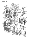
- the exploded perspective view of the outdoor unit 3 will be used to describe the construction thereof.
- the outdoor unit 3 comprises an outdoor unit casing that includes a base plate 41, a left side panel 43, a front panel 44, a protective grill 46, a top panel 47, and humidifying unit casing 48, and other components.
- a fan inlet port 45 and a dividing plate 49 are installed on the rear of the front panel 44.
- an outdoor heat exchanger 24 which is approximately L-shaped in horizontal cross-section is installed on the front surface of the protective grill 46 disposed on the rear surface of the outdoor unit casing.
- a fan motor mount 50 is installed on the front surface of the outdoor heat exchanger 24, and an outdoor fan motor 30 is fixed to this fan motor mount.
- An outdoor fan 29 is installed on the outdoor fan motor. The outdoor fan 29 is driven by means of the outdoor fan motor 30, and forms a negative pressure in the space formed by the fan intake port 45, the dividing plate 49, the left panel 43, the outdoor heat exchanger, and the base plate of the humidifying unit casing 48. After air introduced from the rear surface and the left surface comes into contact with the outdoor heat exchanger 24, it is discharged through the front of the front panel 44.
- Refrigerant circuit components such as a compressor 21, a four way directional control valve 22, an electric valve 25, a liquid shut off valve 27, and a gas shut off valve 28, are disposed in between the dividing plate 49 and the right panel 42, as well as a thermistor 51 that detects the temperature of each of these components.
- a shut off valve cover 52 is installed on the right side of the right panel 42, and serves to protect the liquid shut off valve 27 and the gas shut off valve 28.
- An electric component box 53 is installed above the outdoor fan 29, which contains a printed circuit board 54 on which is mounted circuit components for controlling each component of the outdoor unit.
- a cooling fin 55 is installed on the electrical component box 53, which serves to remove heat produced by the circuit components.
- a fire proof plate 56 for preventing a fire from spreading when it breaks out, and a drip proof plate 57 for preventing water drops from entering from the humidifying unit, are provided in the upper portion of the space in which the refrigerant circuit components, such as the compressor 21 and the like, are stored.
- the humidifying unit 4 is comprised of a humidifying unit casing 48 disposed on the top of the outdoor unit 3.
- a humidifying rotor 58 is disposed inside the humidifying unit casing 48.
- the humidifying rotor 58 adsorbs moisture from the air that it comes in contact with, and is composed of a porous, disk shaped zeolite that has the ability to desorb the adsorbed moisture by heating.
- the humidifying rotor 58 is rotatably supported on a support shaft 59 provided on the humidifying unit casing 48 via a rotor guide 60.
- Gear teeth are formed on the circumferential surface of the humidifying rotor 58, which engage with a rotor drive gear 62 that is installed on a drive shaft on a rotor drive motor 61.
- a heater assembly 64 is disposed on the upper surface of the humidifying rotor 58 such that it covers approximately half thereof.
- the heater assembly 64 is composed of a heating element 66, an upper cover 65 that covers the heating element 66, and a lower cover 69 that includes an intake port 67 for air intake and a discharge port 68 that discharges air that has been heated by the heating element 66.
- the heater assembly 64 is installed above the humidifying rotor 58 via a heater connection plate 63.
- a humidifying fan 70 is disposed below the humidifying rotor 58 in a position facing the heating assembly 64.
- the humidifying fan 70 is a centrifugal fan that is disposed inside the casing and connected to a humidifying side connection duct 72, and is integral with a humidifying fan inlet 71 that is installed below the humidifying rotor 58.
- the humidifying fan 70 discharges air that has flowed through the humidifying rotor 58 into the connection duct 72, and sends humidified air to the indoor unit 2 via a humidifying hose 73 and a humidified air line that is disposed inside the connecting line 6.
- An adsorption side connection duct 74 is provided on the upper surface of the humidifying rotor 58 such that it covers the portion thereof not covered by the heater assembly 64.
- the adsorption side connection duct 74 forms an air flow route that runs from below the humidifying rotor 58, through the humidifying rotor 58, and ends in a adsorption fan container 75 that is adjacent to the container for the humidifying rotor 58.
- a bell mouth 84 that includes a port 85 that connects to the air flow route formed by the adsorption duct 74 is provided above the adsorption fan container 75.
- An adsorption fan 81 is contained in the adsorption fan container 75 and is freely rotatable therein.
- the adsorption fan 81 is a centrifugal fan that is structured so as to take in air from the adsorption side of the bell mouth 84, and discharge this air toward the rear of the adsorption fan container 75.
- the adsorption fan 81 is driven by an adsorption fan motor 83.
- the adsorption fan motor 83 is fixed inside the humidifying unit casing 48 by means of a motor attachment mount 82.
- an air flow is generated by driving the adsorption fan 81, in which air is taken in from the outside, passes through a portion of the humidifying rotor 58, and is discharged to the rear via the adsorption connecting duct and the adsorption fan 81.
- the humidifying rotor 58 adsorbs moisture contained therein.
- an air flow is generated by driving the humidifying fan 70, in which air is taken in from the outside, passes through the humidifying rotor 58 from the lower part to the upper part thereof, is introduced into the upper cover 65 from the lower cover 69 of the intake port 67, is discharged from the discharge port 68 and passed through the humidifying rotor 58 a second time from the upper part to the lower part thereof, and is discharged to the humidifying side connecting duct 72.
- the air flow introduced from the outside comes into contact with the heating element 66 disposed inside the upper cover 65 of the heater assembly 64 and is heated.
- moisture adsorbed in the humidifying rotor 58 can be desorbed and supplied to the indoor unit 2 as humidified air by means of the air flow generated by the humidifying fan 70.
- FIG. 4 An exploded, perspective view of the indoor unit 2 is shown in Fig. 4.
- the indoor unit 2 includes a front grill assembly 101, and a front panel 102 that is mounted on the front of the front grill assembly 101.
- the front grill assembly 101 is comprised of an upper intake port 103 that is formed from a number of slit-shaped openings on the upper surface thereof.
- the front panel 102 is formed from a front intake port 104 that is open on the upper portion and side portions thereof.
- Air filters 105 are interposed between the upper intake port 103 of the front grill assembly 101 and the front intake port 104 of the front panel 102, and serve to clean the air.
- the front grill assembly 101 is installed on a base frame assembly 106 that is positioned on the rear thereof, and is configured to be a casing that contains the internal parts of the indoor unit 2.
- the casing composed of the front grill assembly 102 and the base frame assembly 106 is latched onto an installation plate 107 that is fixed onto an indoor wall, and thereby installed indoors.
- a fan container 109 that stores the cross flow fan 12 is provided in the base frame assembly 106.
- the cross flow fan 12 is installed such that it is freely rotatable via a bearing member 110, and the indoor fan motor 13 is provided on the side of the cross flow fan 12 opposite the bearing member 110.
- a side plate 111 is installed on the outer side of the indoor fan motor 13.
- the indoor heat exchanger 11 is installed such that it surrounds the cross flow fan 12 on the front, top and upper rear portion thereof.
- the indoor heat exchanger 11 includes a large number of cooling fins installed on a heat transfer line that has a plurality of curved portions on both ends thereof in the lengthwise direction. Air that has been taken in from the upper intake port 103 and the front intake port 104 by operation of the cross flow fan 12 passes through the cross flow fan 12 and exchanges heat with the refrigerant that flows inside the heat transfer line.
- the indoor heat exchanger 11 is connected to a refrigerant line 108 that branches off from the indoor heat exchanger 11.
- a drain pan 112 for receiving condensed water produced during heat exchange is provided on the lower part of the indoor heat exchanger 11.
- a drain hose 113 for discharging condensed water to the outside is installed on the drain pan 112.
- the drain pan 112 is constructed to receive the condensed water produced thereby, and drain it off via the drain hose 113.
- An electrical equipment box 114 that contains a printed circuit board that includes a control circuit and the like thereon, and an electrical equipment cover 115 that covers the front of the electrical equipment box 114, are provided on the lower front portion of the front grill assembly 101.
- a discharge port for the air flow that is generated by the cross flow fan 12 is provided on the lower portion of the electrical equipment box 114.
- Horizontal blades 116, 116, and a plurality of vertical blades 117, 117 that are connected to vertical blade connecting rods 118, are pivotably disposed on the discharge port.
- the horizontal blades 116, 116 are constructed such that they can be pivoted up and down by a horizontal blade operation motor 119, and the vertical blades 117, 117 are constructed such that they can be pivoted from left to right by a vertical blade operation motor 120.
- a duct assembly 121 is installed on one side of the base frame assembly 106.
- the duct assembly 121 is comprised of a humidifying hose connector 122 positioned on the bottom thereof, a duct formation 123 positioned in the middle thereof, and a humidified air discharge port 124 that is positioned on the upper portion thereof.
- the humidified air line that branches off from the connecting line 6 is connected to the humidifying hose connector 122 of the duct assembly 121, and introduces humidified air supplied from the humidifying unit 4.
- the duct formation 123 positioned in the middle of the duct assembly 121 forms a space in which humidified air passes therethrough. Humidified air introduced from the humidifying hose connector 122 is conveyed to the end of the duct assembly 121, and is discharged into the air flow generated by the cross flow fan 12 from the humidified air discharge port 124.
- FIG. 5 A cross-section of the connecting line 6 is shown in Fig. 5.
- a line member 161 is formed from an insulating material such as a foam polyethylene material or the like into a tube shape having hollow interior portions.
- a high pressure/low temperature heating line 162, a high pressure/high temperature heating line 163, and a humidified air line 164 are disposed in the interior of the line member 161. From amongst these, the high pressure/high temperature heating line 163 and the humidified air line 164 are disposed inside a high temperature maintenance space 165, and the high pressure/low temperature heating line 162 is disposed in a low temperature line space 166 that is separate from the high temperature maintenance space 165.
- the high pressure/low temperature heating line 162 corresponds to the local line 31 (shown in Fig. 2) that extends from the liquid shut off valve 27 of the outdoor air conditioner unit 5, and the high pressure/high temperature heating line 163 corresponds to the local line 32 (shown in Fig. 2) that extends from the gas shut off valve 28 of the outdoor air conditioner unit 5.
- the high pressure/low temperature heating line 162 is at a low temperature during heating, and because it is disposed inside the line member 161 and in the low temperature line space 166 that is insulated from the high temperature maintenance space 165, the impact that the high pressure/low temperature heating line 162 has is kept to an absolute minimum.
- the high pressure/low temperature heating line 162 the high pressure/high temperature heating line 163, and the humidified air line 164 are disposed inside one line member 161
- the overall diameter of the lines can be kept to a minimum, and can be stored inside conventional ducts for refrigerant lines.
- the air temperature inside a humidified air line can be maintained at a high level and a shortage in the amount of humidity can be prevented, because refrigerant lines that connect an outdoor refrigerant circuit and an indoor refrigerant circuit, and a humidified air line that connects the humidifying unit and the indoor air conditioner, are formed inside and integral with a connecting line that insulates these lines from the outside air by means of an insulating material, and because the high pressure/high temperature heating line and the humidified air line are disposed inside the same space.
- each line to be integral with the connecting line operational efficiency during construction can be improved, and the overall diameter of the lines can be minimized.
- the impact on the humidified air line by the temperature of the refrigerant that passes through the high pressure/low temperature heating line is minimized, and the air temperature inside the humidified air line can be maintained at a high level.
- the refrigerant lines, the humidified air line and the connecting line can be formed to be integral with each other, and operational efficiency during construction can be improved.
Abstract
Description
- The present invention relates to an air conditioner that conveys humidified air to an indoor unit and regulates the humidity of the air inside a room by means of a humidification unit disposed in an outdoor unit.
- In a separate type of air conditioner, an outdoor heat exchanger disposed inside an outdoor unit is connected to an indoor heat exchanger disposed in an indoor unit via refrigerant lines, and each heat exchanger is constructed so that they conduct cooling and heating operations by functioning as a refrigerant condenser and evaporator.
- An outdoor fan that serves to generate air flow is disposed inside the outdoor unit. This outdoor fan introduces outside air into the outdoor unit, which allows heat exchange to occur between the refrigerant that flows through the interior of the outdoor heat exchanger and the air.
- At the same time, an indoor fan is disposed in the indoor unit and serves to generate air flow inside the indoor unit casing. This indoor fan unit draws in indoor air, which allows heat exchange to occur between the refrigerant that flows through the interior of the indoor heat exchanger and the air.
- Generally speaking, there are many times when the indoor relative humidity will drastically decrease during heating operations, due to the fact that there is no supply of moisture while the indoor air temperature rises. Because of this, a humidifying unit has been proposed that is disposed in the air conditioner and supplies humidified air to the room. For example, the humidifying unit is composed of a disk shaped rotor rotatably supported thereon, which is formed from a porous moisture absorbing material such as zeolite and the like that adsorbs moisture from the air, and desorbs the adsorbed moisture by means of heating. The humidifying unit includes a moisture absorption fan that introduces outside air and generates air flow through a part of the rotor in order to allow the rotor to adsorb moisture from the air and a humidifying fan that generates air flow in order to convey humidified air containing moisture desorbed from the rotor to the indoor unit. The air flow from the moisture absorption fan and the air flow from the humidifying fan are structured such that they each flow through the rotor, and the points at which each flow through the rotor are different from each other. In addition, a heater that heats the rotor is disposed at the point where the air flow from the humidifying fan flows through therethrough.
- The moisture contained in the air flow from the moisture absorption fan is adsorbed by the adsorbent material in the rotor. The rotor is driven by a motor, the moisture is desorbed from the rotor at the point in which it is heated by the heater, and the moisture from the humidifying heater can be supplied to the air flow.
- The humidifying unit described above is either installed on or nearby the outdoor unit, adsorbs the moisture from the air taken in from the outside by the moisture absorption fan, and again removes the adsorbed moisture and conveys it to the indoor unit as humidified air.
- The humidified air from the humidifying unit is supplied to the indoor unit by means of a humidified air line. The humidified air line is normally constructed of a polyurethane foam insulating material or the like.
- Humidifying by means of the humidification unit in Japan is mainly conducted during the winter months in Japan because the outside air is dry. In addition, the line running from the humidification unit to the indoor unit is exposed to the cold air outside. Because of this, the air passing through the inside of the humidified air line is refrigerated and the moisture included therein is condensed, and thus there is a danger that the appropriate amount of humidity will not be obtained.
- In addition, there are two types of lines that run from the outdoor unit to the indoor unit, a refrigerant line and a humidified air line, and it is difficult and complex to handle these lines during construction. Moreover, a conventional refrigerant line cannot be easily inserted all the way into a duct because, as a whole, it has a large diameter.
- It is an object of the present invention to maintain the amount of humidity in an air conditioner having a humidifying unit by maintaining the humidified air from the humidifying unit to the indoor unit. at an appropriate temperature, and to devise a reduction in the overall diameter of the lines.
- The air conditioner according to the present invention comprises an outdoor air conditioning unit having an outdoor refrigerant circuit, an indoor air conditioning unit having an indoor refrigerant circuit that is connected to the outdoor refrigerant circuit, and a humidifying unit that takes in moisture from the outside air, generates humidified air, and supplies the humidified air to the indoor air conditioning unit, wherein refrigerant lines that connect the outdoor refrigerant circuit and the indoor refrigerant circuit, and a humidified air line that connects the humidifying unit and indoor air conditioner, are formed inside and integral with a connecting line that insulates the lines from the outside air by means of an insulating material, and the high pressure/high temperature heating line and the humidified air line are disposed inside the same space.
- In this situation, the air temperature inside a humidified air line can be maintained at a high level and a shortage in the amount of humidity can be prevented. In addition, by forming each line to be integral with the connecting line, operational efficiency during construction can be improved, and the overall diameter of the lines can be minimized.
- Here, from amongst the refrigerant lines, the high pressure/low temperature heating line can be configured such that it is disposed inside a space that is different from the space formed by the high pressure/high temperature heating line and the humidified air line.
- In this situation, the impact on the humidified air line by the temperature of the refrigerant that passes through the high pressure/low temperature heating line is minimized, and the air temperature inside the humidified air line can be maintained at a high level.
- In addition, an electrical connection line that electrically connects the outdoor air conditioning unit and the indoor air conditioning unit is disposed inside the connecting line.
- In this situation, the refrigerant lines, the humidified air line and the connecting line can be formed to be integral with each other, and operational efficiency during construction can be improved.
-
- Fig. 1 is a perspective view showing the exterior structure of an air conditioner in which a first embodiment of the present invention has been adapted.
- Fig. 2 is a diagram describing a refrigerant circuit.
- Fig. 3 is an exploded perspective view of a outdoor unit.
- Fig. 4 is an exploded perspective view of an indoor unit.
- Fig. 5 is a cross-sectional view of a line member.
-
- The exterior of an air conditioner in which a first embodiment of the present invention has been adapted is shown in Fig. 1.
- The
air conditioner 1 is comprised of anindoor unit 2 that is installed on an indoor wall or the like, and anoutdoor unit 3 that is disposed outdoors. Theoutdoor unit 3 is comprised of an outdoorair conditioner unit 5 that contains an outdoor heat exchanger, an outdoor fan, and the like, and ahumidifying unit 4 that conveys humidified air to theindoor unit 2. - The
indoor unit 2 contains an indoor heat exchanger, theoutdoor unit 3 contains an outdoor heat exchanger, and both heat exchangers constitute a refrigerant circuit which is connected by means of a refrigerant line. In addition, a humidified air line for supplying humidified air from the humidifyingunit 4 to theindoor unit 2 is provided between thehumidifying unit 4 and theindoor unit 2. The refrigerant line and the humidified air line are disposed inside a connectingline 6 that is insulated from the outside air by means of an insulating material. - An example of the refrigerant circuit employed in the
air conditioner 1 is shown in Fig. 2. - An
indoor heat exchanger 11 is provided in theindoor unit 2. Theindoor heat exchanger 11 is comprised of a heat transfer line that has a plurality of curved portions on both ends thereof in the lengthwise direction, and a plurality of fins through which the heat transfer line passes, and exchanges heat with the air that comes in contact therewith. - In addition, a
cross flow fan 12 that takes in indoor air, and discharges this air indoors after heat exchange has taken place with theindoor heat exchanger 11, is provided in theindoor unit 2. Thecross flow fan 12 is cylindrical in shape, is comprised of blades disposed around the circumferential surface of a rotary shaft, and generates air flow in a direction that is perpendicular to the rotary shaft. Thecross flow fan 12 is driven by means of afan motor 13 that is provided inside theindoor unit 2. - A
compressor 21, a four waydirectional control valve 22 that is connected to the discharge side of thecompressor 21, anaccumulator 23 that is connected to the intake side of thecompressor 21, anoutdoor heat exchanger 24 that is connected to the four waydirectional control valve 22, and adecompressor 25 that is an electric expansion valve and connected to theoutdoor heat exchanger 24, are provided in the outdoorair conditioning unit 5. Thedecompressor 25 is connected to alocal line 31 via afilter 26 and a liquid shut offvalve 27, and is connected to one end of theindoor heat exchanger 11 via thelocal line 31. In addition, the four waydirectional control valve 22 is connected to alocal line 32 via a gas shut offvalve 28, and is connected to the other end of theindoor heat exchanger 11 via thislocal line 32. Thelocal lines line 6 shown in Fig. 1. - A
propeller fan 29 that discharges air outside after heat exchange with theoutdoor heat exchanger 24 is provided in the outdoorair conditioning unit 5. Thepropeller fan 29 is driven by afan motor 30. - The exploded perspective view of the
outdoor unit 3 will be used to describe the construction thereof. - The
outdoor unit 3 comprises an outdoor unit casing that includes abase plate 41, aleft side panel 43, afront panel 44, aprotective grill 46, atop panel 47, and humidifying unit casing 48, and other components. - A
fan inlet port 45 and a dividingplate 49 are installed on the rear of thefront panel 44. In addition, anoutdoor heat exchanger 24 which is approximately L-shaped in horizontal cross-section is installed on the front surface of theprotective grill 46 disposed on the rear surface of the outdoor unit casing. - A
fan motor mount 50 is installed on the front surface of theoutdoor heat exchanger 24, and anoutdoor fan motor 30 is fixed to this fan motor mount. Anoutdoor fan 29 is installed on the outdoor fan motor. Theoutdoor fan 29 is driven by means of theoutdoor fan motor 30, and forms a negative pressure in the space formed by thefan intake port 45, the dividingplate 49, theleft panel 43, the outdoor heat exchanger, and the base plate of the humidifying unit casing 48. After air introduced from the rear surface and the left surface comes into contact with theoutdoor heat exchanger 24, it is discharged through the front of thefront panel 44. - Refrigerant circuit components such as a
compressor 21, a four waydirectional control valve 22, anelectric valve 25, a liquid shut offvalve 27, and a gas shut offvalve 28, are disposed in between the dividingplate 49 and theright panel 42, as well as athermistor 51 that detects the temperature of each of these components. A shut offvalve cover 52 is installed on the right side of theright panel 42, and serves to protect the liquid shut offvalve 27 and the gas shut offvalve 28. - An
electric component box 53 is installed above theoutdoor fan 29, which contains a printedcircuit board 54 on which is mounted circuit components for controlling each component of the outdoor unit. A coolingfin 55 is installed on theelectrical component box 53, which serves to remove heat produced by the circuit components. - In addition, a
fire proof plate 56 for preventing a fire from spreading when it breaks out, and adrip proof plate 57 for preventing water drops from entering from the humidifying unit, are provided in the upper portion of the space in which the refrigerant circuit components, such as thecompressor 21 and the like, are stored. - The
humidifying unit 4 is comprised of a humidifying unit casing 48 disposed on the top of theoutdoor unit 3. A humidifyingrotor 58 is disposed inside the humidifying unit casing 48. The humidifyingrotor 58 adsorbs moisture from the air that it comes in contact with, and is composed of a porous, disk shaped zeolite that has the ability to desorb the adsorbed moisture by heating. The humidifyingrotor 58 is rotatably supported on a support shaft 59 provided on the humidifying unit casing 48 via arotor guide 60. Gear teeth are formed on the circumferential surface of thehumidifying rotor 58, which engage with arotor drive gear 62 that is installed on a drive shaft on arotor drive motor 61. - A
heater assembly 64 is disposed on the upper surface of thehumidifying rotor 58 such that it covers approximately half thereof. Theheater assembly 64 is composed of aheating element 66, anupper cover 65 that covers theheating element 66, and a lower cover 69 that includes an intake port 67 for air intake and a discharge port 68 that discharges air that has been heated by theheating element 66. Theheater assembly 64 is installed above the humidifyingrotor 58 via aheater connection plate 63. - A humidifying
fan 70 is disposed below the humidifyingrotor 58 in a position facing theheating assembly 64. The humidifyingfan 70 is a centrifugal fan that is disposed inside the casing and connected to a humidifyingside connection duct 72, and is integral with a humidifyingfan inlet 71 that is installed below the humidifyingrotor 58. The humidifyingfan 70 discharges air that has flowed through the humidifyingrotor 58 into theconnection duct 72, and sends humidified air to theindoor unit 2 via a humidifying hose 73 and a humidified air line that is disposed inside the connectingline 6. - An adsorption
side connection duct 74 is provided on the upper surface of thehumidifying rotor 58 such that it covers the portion thereof not covered by theheater assembly 64. The adsorptionside connection duct 74 forms an air flow route that runs from below the humidifyingrotor 58, through the humidifyingrotor 58, and ends in aadsorption fan container 75 that is adjacent to the container for thehumidifying rotor 58. - A
bell mouth 84 that includes aport 85 that connects to the air flow route formed by theadsorption duct 74 is provided above theadsorption fan container 75. Anadsorption fan 81 is contained in theadsorption fan container 75 and is freely rotatable therein. Theadsorption fan 81 is a centrifugal fan that is structured so as to take in air from the adsorption side of thebell mouth 84, and discharge this air toward the rear of theadsorption fan container 75. Theadsorption fan 81 is driven by anadsorption fan motor 83. Theadsorption fan motor 83 is fixed inside the humidifying unit casing 48 by means of amotor attachment mount 82. - Moreover, a
power source substrate 79 an electric component casing that is made up of anelectric component box 76 and an electricalcomponent box lid 77, which contains a printedcircuit board 78 therein, are disposed inside the humidifying unit casing 48. - In this type of
humidifying unit 4, an air flow is generated by driving theadsorption fan 81, in which air is taken in from the outside, passes through a portion of thehumidifying rotor 58, and is discharged to the rear via the adsorption connecting duct and theadsorption fan 81. When the air taken in from the outside passes through the humidifyingrotor 58, the humidifyingrotor 58 adsorbs moisture contained therein. - In addition, an air flow is generated by driving the
humidifying fan 70, in which air is taken in from the outside, passes through the humidifyingrotor 58 from the lower part to the upper part thereof, is introduced into theupper cover 65 from the lower cover 69 of the intake port 67, is discharged from the discharge port 68 and passed through the humidifying rotor 58 a second time from the upper part to the lower part thereof, and is discharged to the humidifyingside connecting duct 72. When this occurs, the air flow introduced from the outside comes into contact with theheating element 66 disposed inside theupper cover 65 of theheater assembly 64 and is heated. Thus, moisture adsorbed in thehumidifying rotor 58 can be desorbed and supplied to theindoor unit 2 as humidified air by means of the air flow generated by the humidifyingfan 70. - An exploded, perspective view of the
indoor unit 2 is shown in Fig. 4. - In Fig. 4, the
indoor unit 2 includes afront grill assembly 101, and afront panel 102 that is mounted on the front of thefront grill assembly 101. Thefront grill assembly 101 is comprised of anupper intake port 103 that is formed from a number of slit-shaped openings on the upper surface thereof. In addition, thefront panel 102 is formed from afront intake port 104 that is open on the upper portion and side portions thereof. -
Air filters 105 are interposed between theupper intake port 103 of thefront grill assembly 101 and thefront intake port 104 of thefront panel 102, and serve to clean the air. - The
front grill assembly 101 is installed on abase frame assembly 106 that is positioned on the rear thereof, and is configured to be a casing that contains the internal parts of theindoor unit 2. The casing composed of thefront grill assembly 102 and thebase frame assembly 106 is latched onto aninstallation plate 107 that is fixed onto an indoor wall, and thereby installed indoors. - A
fan container 109 that stores thecross flow fan 12 is provided in thebase frame assembly 106. The cross flowfan 12 is installed such that it is freely rotatable via a bearingmember 110, and theindoor fan motor 13 is provided on the side of thecross flow fan 12 opposite the bearingmember 110. Aside plate 111 is installed on the outer side of theindoor fan motor 13. - The
indoor heat exchanger 11 is installed such that it surrounds thecross flow fan 12 on the front, top and upper rear portion thereof. Theindoor heat exchanger 11 includes a large number of cooling fins installed on a heat transfer line that has a plurality of curved portions on both ends thereof in the lengthwise direction. Air that has been taken in from theupper intake port 103 and thefront intake port 104 by operation of thecross flow fan 12 passes through thecross flow fan 12 and exchanges heat with the refrigerant that flows inside the heat transfer line. Theindoor heat exchanger 11 is connected to arefrigerant line 108 that branches off from theindoor heat exchanger 11. - A
drain pan 112 for receiving condensed water produced during heat exchange is provided on the lower part of theindoor heat exchanger 11. Adrain hose 113 for discharging condensed water to the outside is installed on thedrain pan 112. During cooling operations, moisture in the air that comes into contact with theindoor heat exchanger 11 condenses and drips downward because theindoor heat exchanger 11 acts as an evaporator. Thedrain pan 112 is constructed to receive the condensed water produced thereby, and drain it off via thedrain hose 113. - An
electrical equipment box 114 that contains a printed circuit board that includes a control circuit and the like thereon, and anelectrical equipment cover 115 that covers the front of theelectrical equipment box 114, are provided on the lower front portion of thefront grill assembly 101. In addition, a discharge port for the air flow that is generated by thecross flow fan 12 is provided on the lower portion of theelectrical equipment box 114.Horizontal blades vertical blades blade connecting rods 118, are pivotably disposed on the discharge port. Thehorizontal blades blade operation motor 119, and thevertical blades blade operation motor 120. - A
duct assembly 121 is installed on one side of thebase frame assembly 106. Theduct assembly 121 is comprised of ahumidifying hose connector 122 positioned on the bottom thereof, a duct formation 123 positioned in the middle thereof, and a humidifiedair discharge port 124 that is positioned on the upper portion thereof. The humidified air line that branches off from the connectingline 6 is connected to thehumidifying hose connector 122 of theduct assembly 121, and introduces humidified air supplied from thehumidifying unit 4. The duct formation 123 positioned in the middle of theduct assembly 121 forms a space in which humidified air passes therethrough. Humidified air introduced from thehumidifying hose connector 122 is conveyed to the end of theduct assembly 121, and is discharged into the air flow generated by thecross flow fan 12 from the humidifiedair discharge port 124. - A cross-section of the connecting
line 6 is shown in Fig. 5. - A
line member 161 is formed from an insulating material such as a foam polyethylene material or the like into a tube shape having hollow interior portions. A high pressure/lowtemperature heating line 162, a high pressure/hightemperature heating line 163, and a humidifiedair line 164 are disposed in the interior of theline member 161. From amongst these, the high pressure/hightemperature heating line 163 and the humidifiedair line 164 are disposed inside a hightemperature maintenance space 165, and the high pressure/lowtemperature heating line 162 is disposed in a lowtemperature line space 166 that is separate from the hightemperature maintenance space 165. - The high pressure/low
temperature heating line 162 corresponds to the local line 31 (shown in Fig. 2) that extends from the liquid shut offvalve 27 of the outdoorair conditioner unit 5, and the high pressure/hightemperature heating line 163 corresponds to the local line 32 (shown in Fig. 2) that extends from the gas shut offvalve 28 of the outdoorair conditioner unit 5. - When humidifying operations take place during the dry winter months, it is thought that there will be many times in which heating operations take place simultaneously because the outside air temperature is low. Thus, the refrigerant that passes through the high pressure/high
temperature heating line 163 during heating operations is at a high temperature, and the air inside the humidifiedair line 164 disposed in the same space as the high pressure/hightemperature heating line 163 can be maintained at a high temperature. Thus, the moisture in the air conveyed inside the humidifiedair line 164 will not be condensed, and a reduction in the amount of humidity can be prevented. The high pressure/lowtemperature heating line 162 is at a low temperature during heating, and because it is disposed inside theline member 161 and in the lowtemperature line space 166 that is insulated from the hightemperature maintenance space 165, the impact that the high pressure/lowtemperature heating line 162 has is kept to an absolute minimum. - In addition, because the high pressure/low
temperature heating line 162, the high pressure/hightemperature heating line 163, and the humidifiedair line 164 are disposed inside oneline member 161, the overall diameter of the lines can be kept to a minimum, and can be stored inside conventional ducts for refrigerant lines. -
- (A) In Fig. 5, a
space 168 is formed inside the hightemperature maintenance space 165, and the high pressure/hightemperature heating line 163 and the humidifiedair line 164 are stored therein in close proximity to each other. Here, the temperature is maintained at a high level by the high pressure/hightemperature heating line 163, and the amount of humidity inside the humidifiedair line 164 can be maintained. - (B) As shown in Fig. 5, an
electric connection line 167 for electrically connecting the outdoorair conditioner unit 5 and the indoorair conditioner unit 2 can be disposed inside theline member 161. In this case, it becomes possible to form the refrigerant lines, the humidified air line and the electric connection line to be integral with each other, and thus improve operational efficiency during construction. -
- With the air conditioner according to
claim 1 of the present invention, the air temperature inside a humidified air line can be maintained at a high level and a shortage in the amount of humidity can be prevented, because refrigerant lines that connect an outdoor refrigerant circuit and an indoor refrigerant circuit, and a humidified air line that connects the humidifying unit and the indoor air conditioner, are formed inside and integral with a connecting line that insulates these lines from the outside air by means of an insulating material, and because the high pressure/high temperature heating line and the humidified air line are disposed inside the same space. In addition, by forming each line to be integral with the connecting line, operational efficiency during construction can be improved, and the overall diameter of the lines can be minimized. - With the air conditioner according to
claim 2, the impact on the humidified air line by the temperature of the refrigerant that passes through the high pressure/low temperature heating line is minimized, and the air temperature inside the humidified air line can be maintained at a high level. - With the air conditioner according to
claim 3, the refrigerant lines, the humidified air line and the connecting line can be formed to be integral with each other, and operational efficiency during construction can be improved.
Claims (3)
- An air conditioner (1), comprising:wherein refrigerant lines (162, 163) that connect said outdoor refrigerant circuit and said indoor refrigerant circuit, and a humidified air line (164) that connects said humidifying unit (4) and said indoor air conditioner (2), are formed inside and integral with a connecting line (161) that insulates said lines from outside air by means of an insulating material, and said high pressure/high temperature heating line (163) and said humidified air line (164) are disposed inside the same space (165).an outdoor air conditioning unit having an outdoor refrigerant circuit (5);an indoor air conditioning unit (2) having an indoor refrigerant circuit connected to said outdoor refrigerant circuit; anda humidifying unit (4) that removes moisture from outside air and generates humidified air, and supplies said humidified air to said indoor air conditioner (2);
- The air conditioner set forth in claim 1, wherein amongst said refrigerant lines, said high pressure/low temperature line (162) is disposed inside a space (166) that is different from said space (165) in which said high pressure/high temperature heating line (163) and said humidified air line (164) are disposed.
- The air conditioner set forth in claim 1 or 2, wherein an electrical connection line (167) that electrically connects said outdoor air conditioning unit (5) and said indoor air conditioning unit (2) is disposed inside said connecting line (161).
Applications Claiming Priority (3)
| Application Number | Priority Date | Filing Date | Title |
|---|---|---|---|
| JP2000276292 | 2000-09-12 | ||
| JP2000276292A JP2002089904A (en) | 2000-09-12 | 2000-09-12 | Air conditioner |
| PCT/JP2001/007337 WO2002023095A1 (en) | 2000-09-12 | 2001-08-27 | Air conditioner |
Publications (3)
| Publication Number | Publication Date |
|---|---|
| EP1318355A1 true EP1318355A1 (en) | 2003-06-11 |
| EP1318355A4 EP1318355A4 (en) | 2005-11-16 |
| EP1318355B1 EP1318355B1 (en) | 2008-10-01 |
Family
ID=18761787
Family Applications (1)
| Application Number | Title | Priority Date | Filing Date |
|---|---|---|---|
| EP01958534A Expired - Lifetime EP1318355B1 (en) | 2000-09-12 | 2001-08-27 | Air conditioner |
Country Status (8)
| Country | Link |
|---|---|
| EP (1) | EP1318355B1 (en) |
| JP (1) | JP2002089904A (en) |
| KR (1) | KR20020061592A (en) |
| CN (1) | CN1161569C (en) |
| AT (1) | ATE409838T1 (en) |
| DE (1) | DE60135997D1 (en) |
| ES (1) | ES2312462T3 (en) |
| WO (1) | WO2002023095A1 (en) |
Cited By (1)
| Publication number | Priority date | Publication date | Assignee | Title |
|---|---|---|---|---|
| WO2015068946A1 (en) | 2013-11-11 | 2015-05-14 | Lg Electronics Inc. | Signal transmission device for air conditioner |
Families Citing this family (2)
| Publication number | Priority date | Publication date | Assignee | Title |
|---|---|---|---|---|
| CN104764094B (en) * | 2015-03-26 | 2017-06-06 | 广东美的制冷设备有限公司 | The control method of humidifying air conditioner and humidifying air conditioner |
| CN106225115B (en) * | 2016-08-26 | 2019-06-04 | 芜湖美智空调设备有限公司 | Humidifier, air-conditioning system and its control method |
Citations (5)
| Publication number | Priority date | Publication date | Assignee | Title |
|---|---|---|---|---|
| JPH02219934A (en) * | 1989-02-21 | 1990-09-03 | Daikin Ind Ltd | Humidifying device for air conditioner |
| JPH08128681A (en) * | 1994-10-28 | 1996-05-21 | Sharp Corp | Air conditioner with humidifying function |
| JPH1019303A (en) * | 1996-07-04 | 1998-01-23 | Daikin Ind Ltd | Ventilation duct structure for separate type air conditioner |
| JPH10232036A (en) * | 1997-02-20 | 1998-09-02 | Daikin Ind Ltd | Humidifying unit |
| JP2001090999A (en) * | 1999-09-27 | 2001-04-03 | Daikin Ind Ltd | Laying structure of humidifying hose |
Family Cites Families (3)
| Publication number | Priority date | Publication date | Assignee | Title |
|---|---|---|---|---|
| JPH03526U (en) * | 1989-05-24 | 1991-01-07 | ||
| JP3132940B2 (en) * | 1993-03-02 | 2001-02-05 | 松下電器産業株式会社 | Air conditioner with humidification function |
| JPH08240328A (en) * | 1995-03-02 | 1996-09-17 | Daikin Ind Ltd | Separate type air-conditioning machine |
-
2000
- 2000-09-12 JP JP2000276292A patent/JP2002089904A/en active Pending
-
2001
- 2001-08-27 DE DE60135997T patent/DE60135997D1/en not_active Expired - Lifetime
- 2001-08-27 ES ES01958534T patent/ES2312462T3/en not_active Expired - Lifetime
- 2001-08-27 AT AT01958534T patent/ATE409838T1/en not_active IP Right Cessation
- 2001-08-27 WO PCT/JP2001/007337 patent/WO2002023095A1/en active IP Right Grant
- 2001-08-27 KR KR1020027002462A patent/KR20020061592A/en not_active Application Discontinuation
- 2001-08-27 CN CNB018026117A patent/CN1161569C/en not_active Expired - Fee Related
- 2001-08-27 EP EP01958534A patent/EP1318355B1/en not_active Expired - Lifetime
Patent Citations (5)
| Publication number | Priority date | Publication date | Assignee | Title |
|---|---|---|---|---|
| JPH02219934A (en) * | 1989-02-21 | 1990-09-03 | Daikin Ind Ltd | Humidifying device for air conditioner |
| JPH08128681A (en) * | 1994-10-28 | 1996-05-21 | Sharp Corp | Air conditioner with humidifying function |
| JPH1019303A (en) * | 1996-07-04 | 1998-01-23 | Daikin Ind Ltd | Ventilation duct structure for separate type air conditioner |
| JPH10232036A (en) * | 1997-02-20 | 1998-09-02 | Daikin Ind Ltd | Humidifying unit |
| JP2001090999A (en) * | 1999-09-27 | 2001-04-03 | Daikin Ind Ltd | Laying structure of humidifying hose |
Non-Patent Citations (6)
| Title |
|---|
| PATENT ABSTRACTS OF JAPAN vol. 014, no. 523 (M-1049), 16 November 1990 (1990-11-16) & JP 02 219934 A (DAIKIN IND LTD), 3 September 1990 (1990-09-03) * |
| PATENT ABSTRACTS OF JAPAN vol. 1996, no. 09, 30 September 1996 (1996-09-30) & JP 08 128681 A (SHARP CORP), 21 May 1996 (1996-05-21) * |
| PATENT ABSTRACTS OF JAPAN vol. 1998, no. 05, 30 April 1998 (1998-04-30) & JP 10 019303 A (DAIKIN IND LTD), 23 January 1998 (1998-01-23) * |
| PATENT ABSTRACTS OF JAPAN vol. 1998, no. 14, 31 December 1998 (1998-12-31) & JP 10 232036 A (DAIKIN IND LTD), 2 September 1998 (1998-09-02) * |
| PATENT ABSTRACTS OF JAPAN vol. 2000, no. 21, 3 August 2001 (2001-08-03) & JP 2001 090999 A (DAIKIN IND LTD), 3 April 2001 (2001-04-03) * |
| See also references of WO0223095A1 * |
Cited By (3)
| Publication number | Priority date | Publication date | Assignee | Title |
|---|---|---|---|---|
| WO2015068946A1 (en) | 2013-11-11 | 2015-05-14 | Lg Electronics Inc. | Signal transmission device for air conditioner |
| EP3069085A4 (en) * | 2013-11-11 | 2017-08-30 | LG Electronics Inc. | Signal transmission device for air conditioner |
| US10381813B2 (en) | 2013-11-11 | 2019-08-13 | Lg Electronics Inc. | Signal transmission device for air conditioner |
Also Published As
| Publication number | Publication date |
|---|---|
| ES2312462T3 (en) | 2009-03-01 |
| EP1318355B1 (en) | 2008-10-01 |
| JP2002089904A (en) | 2002-03-27 |
| DE60135997D1 (en) | 2008-11-13 |
| KR20020061592A (en) | 2002-07-24 |
| ATE409838T1 (en) | 2008-10-15 |
| CN1161569C (en) | 2004-08-11 |
| WO2002023095A1 (en) | 2002-03-21 |
| CN1388883A (en) | 2003-01-01 |
| EP1318355A4 (en) | 2005-11-16 |
Similar Documents
| Publication | Publication Date | Title |
|---|---|---|
| CN105378389A (en) | Air-conditioner | |
| CN101815906A (en) | Humidity control device and ventilation device | |
| CN217082837U (en) | Air humidifying device | |
| JP3786090B2 (en) | Air conditioner and control method of air conditioner | |
| EP1318356B1 (en) | Air conditioner | |
| KR100553417B1 (en) | Ventilator | |
| JP4677658B2 (en) | Air conditioner | |
| EP1598600A2 (en) | Air conditioning system with humidity adjusting apparatus. | |
| JP3719118B2 (en) | Air conditioner | |
| CN102003747A (en) | Movable type air conditioner | |
| KR101270079B1 (en) | Indoor unit for ghp or ehp | |
| EP2016341A2 (en) | Dehumidifier | |
| EP1318355B1 (en) | Air conditioner | |
| JP5170181B2 (en) | Air conditioner | |
| JP3564525B2 (en) | Air conditioner | |
| JP5471185B2 (en) | Air conditioner | |
| JP3900004B2 (en) | Air conditioner | |
| KR200154186Y1 (en) | Airconditioner | |
| JP3564526B2 (en) | Air conditioner | |
| CN215909302U (en) | Air interchanger | |
| JP2019184124A (en) | Air conditioner | |
| JP2002089893A (en) | Air conditioner | |
| JP2008241212A (en) | Air conditioner | |
| JP2002089903A (en) | Air conditioner | |
| JP3858914B2 (en) | Ventilator and air conditioner |
Legal Events
| Date | Code | Title | Description |
|---|---|---|---|
| PUAI | Public reference made under article 153(3) epc to a published international application that has entered the european phase |
Free format text: ORIGINAL CODE: 0009012 |
|
| 17P | Request for examination filed |
Effective date: 20020516 |
|
| AK | Designated contracting states |
Designated state(s): AT BE CH CY DE DK ES FI FR GB GR IE IT LI LU MC NL PT SE TR |
|
| A4 | Supplementary search report drawn up and despatched |
Effective date: 20050929 |
|
| RIC1 | Information provided on ipc code assigned before grant |
Ipc: 7F 24F 1/00 B Ipc: 7F 24F 6/00 A Ipc: 7F 24F 3/14 B Ipc: 7F 24F 1/02 B Ipc: 7F 24F 6/06 B |
|
| 17Q | First examination report despatched |
Effective date: 20061211 |
|
| GRAP | Despatch of communication of intention to grant a patent |
Free format text: ORIGINAL CODE: EPIDOSNIGR1 |
|
| GRAS | Grant fee paid |
Free format text: ORIGINAL CODE: EPIDOSNIGR3 |
|
| GRAA | (expected) grant |
Free format text: ORIGINAL CODE: 0009210 |
|
| AK | Designated contracting states |
Kind code of ref document: B1 Designated state(s): AT BE CH CY DE DK ES FI FR GB GR IE IT LI LU MC NL PT SE TR |
|
| REG | Reference to a national code |
Ref country code: GB Ref legal event code: FG4D |
|
| REG | Reference to a national code |
Ref country code: CH Ref legal event code: EP |
|
| REG | Reference to a national code |
Ref country code: IE Ref legal event code: FG4D |
|
| REF | Corresponds to: |
Ref document number: 60135997 Country of ref document: DE Date of ref document: 20081113 Kind code of ref document: P |
|
| REG | Reference to a national code |
Ref country code: ES Ref legal event code: FG2A Ref document number: 2312462 Country of ref document: ES Kind code of ref document: T3 |
|
| NLV1 | Nl: lapsed or annulled due to failure to fulfill the requirements of art. 29p and 29m of the patents act | ||
| PG25 | Lapsed in a contracting state [announced via postgrant information from national office to epo] |
Ref country code: AT Free format text: LAPSE BECAUSE OF FAILURE TO SUBMIT A TRANSLATION OF THE DESCRIPTION OR TO PAY THE FEE WITHIN THE PRESCRIBED TIME-LIMIT Effective date: 20081001 |
|
| PG25 | Lapsed in a contracting state [announced via postgrant information from national office to epo] |
Ref country code: PT Free format text: LAPSE BECAUSE OF FAILURE TO SUBMIT A TRANSLATION OF THE DESCRIPTION OR TO PAY THE FEE WITHIN THE PRESCRIBED TIME-LIMIT Effective date: 20090302 Ref country code: NL Free format text: LAPSE BECAUSE OF FAILURE TO SUBMIT A TRANSLATION OF THE DESCRIPTION OR TO PAY THE FEE WITHIN THE PRESCRIBED TIME-LIMIT Effective date: 20081001 Ref country code: FI Free format text: LAPSE BECAUSE OF FAILURE TO SUBMIT A TRANSLATION OF THE DESCRIPTION OR TO PAY THE FEE WITHIN THE PRESCRIBED TIME-LIMIT Effective date: 20081001 |
|
| PG25 | Lapsed in a contracting state [announced via postgrant information from national office to epo] |
Ref country code: DK Free format text: LAPSE BECAUSE OF FAILURE TO SUBMIT A TRANSLATION OF THE DESCRIPTION OR TO PAY THE FEE WITHIN THE PRESCRIBED TIME-LIMIT Effective date: 20081001 Ref country code: BE Free format text: LAPSE BECAUSE OF FAILURE TO SUBMIT A TRANSLATION OF THE DESCRIPTION OR TO PAY THE FEE WITHIN THE PRESCRIBED TIME-LIMIT Effective date: 20081001 |
|
| PLBE | No opposition filed within time limit |
Free format text: ORIGINAL CODE: 0009261 |
|
| STAA | Information on the status of an ep patent application or granted ep patent |
Free format text: STATUS: NO OPPOSITION FILED WITHIN TIME LIMIT |
|
| PG25 | Lapsed in a contracting state [announced via postgrant information from national office to epo] |
Ref country code: SE Free format text: LAPSE BECAUSE OF FAILURE TO SUBMIT A TRANSLATION OF THE DESCRIPTION OR TO PAY THE FEE WITHIN THE PRESCRIBED TIME-LIMIT Effective date: 20090101 |
|
| 26N | No opposition filed |
Effective date: 20090702 |
|
| PG25 | Lapsed in a contracting state [announced via postgrant information from national office to epo] |
Ref country code: MC Free format text: LAPSE BECAUSE OF NON-PAYMENT OF DUE FEES Effective date: 20090831 |
|
| REG | Reference to a national code |
Ref country code: CH Ref legal event code: PL |
|
| PG25 | Lapsed in a contracting state [announced via postgrant information from national office to epo] |
Ref country code: LI Free format text: LAPSE BECAUSE OF NON-PAYMENT OF DUE FEES Effective date: 20090831 Ref country code: CH Free format text: LAPSE BECAUSE OF NON-PAYMENT OF DUE FEES Effective date: 20090831 |
|
| REG | Reference to a national code |
Ref country code: IE Ref legal event code: MM4A |
|
| PG25 | Lapsed in a contracting state [announced via postgrant information from national office to epo] |
Ref country code: IE Free format text: LAPSE BECAUSE OF NON-PAYMENT OF DUE FEES Effective date: 20090827 |
|
| PG25 | Lapsed in a contracting state [announced via postgrant information from national office to epo] |
Ref country code: GR Free format text: LAPSE BECAUSE OF FAILURE TO SUBMIT A TRANSLATION OF THE DESCRIPTION OR TO PAY THE FEE WITHIN THE PRESCRIBED TIME-LIMIT Effective date: 20090102 |
|
| PG25 | Lapsed in a contracting state [announced via postgrant information from national office to epo] |
Ref country code: LU Free format text: LAPSE BECAUSE OF NON-PAYMENT OF DUE FEES Effective date: 20090827 |
|
| PG25 | Lapsed in a contracting state [announced via postgrant information from national office to epo] |
Ref country code: TR Free format text: LAPSE BECAUSE OF FAILURE TO SUBMIT A TRANSLATION OF THE DESCRIPTION OR TO PAY THE FEE WITHIN THE PRESCRIBED TIME-LIMIT Effective date: 20081001 |
|
| PG25 | Lapsed in a contracting state [announced via postgrant information from national office to epo] |
Ref country code: CY Free format text: LAPSE BECAUSE OF FAILURE TO SUBMIT A TRANSLATION OF THE DESCRIPTION OR TO PAY THE FEE WITHIN THE PRESCRIBED TIME-LIMIT Effective date: 20081001 |
|
| REG | Reference to a national code |
Ref country code: FR Ref legal event code: PLFP Year of fee payment: 16 |
|
| PGFP | Annual fee paid to national office [announced via postgrant information from national office to epo] |
Ref country code: GB Payment date: 20160824 Year of fee payment: 16 Ref country code: DE Payment date: 20160823 Year of fee payment: 16 Ref country code: IT Payment date: 20160822 Year of fee payment: 16 |
|
| PGFP | Annual fee paid to national office [announced via postgrant information from national office to epo] |
Ref country code: FR Payment date: 20160712 Year of fee payment: 16 |
|
| PGFP | Annual fee paid to national office [announced via postgrant information from national office to epo] |
Ref country code: ES Payment date: 20160712 Year of fee payment: 16 |
|
| REG | Reference to a national code |
Ref country code: DE Ref legal event code: R119 Ref document number: 60135997 Country of ref document: DE |
|
| GBPC | Gb: european patent ceased through non-payment of renewal fee |
Effective date: 20170827 |
|
| REG | Reference to a national code |
Ref country code: FR Ref legal event code: ST Effective date: 20180430 |
|
| PG25 | Lapsed in a contracting state [announced via postgrant information from national office to epo] |
Ref country code: GB Free format text: LAPSE BECAUSE OF NON-PAYMENT OF DUE FEES Effective date: 20170827 Ref country code: DE Free format text: LAPSE BECAUSE OF NON-PAYMENT OF DUE FEES Effective date: 20180301 |
|
| PG25 | Lapsed in a contracting state [announced via postgrant information from national office to epo] |
Ref country code: IT Free format text: LAPSE BECAUSE OF NON-PAYMENT OF DUE FEES Effective date: 20170827 Ref country code: FR Free format text: LAPSE BECAUSE OF NON-PAYMENT OF DUE FEES Effective date: 20170831 |
|
| REG | Reference to a national code |
Ref country code: ES Ref legal event code: FD2A Effective date: 20181024 |
|
| PG25 | Lapsed in a contracting state [announced via postgrant information from national office to epo] |
Ref country code: ES Free format text: LAPSE BECAUSE OF NON-PAYMENT OF DUE FEES Effective date: 20170828 |