EP1318320A2 - Brake lining of brake device - Google Patents
Brake lining of brake device Download PDFInfo
- Publication number
- EP1318320A2 EP1318320A2 EP02257760A EP02257760A EP1318320A2 EP 1318320 A2 EP1318320 A2 EP 1318320A2 EP 02257760 A EP02257760 A EP 02257760A EP 02257760 A EP02257760 A EP 02257760A EP 1318320 A2 EP1318320 A2 EP 1318320A2
- Authority
- EP
- European Patent Office
- Prior art keywords
- friction
- brake
- brake lining
- sliding speed
- friction material
- Prior art date
- Legal status (The legal status is an assumption and is not a legal conclusion. Google has not performed a legal analysis and makes no representation as to the accuracy of the status listed.)
- Granted
Links
- 239000002783 friction material Substances 0.000 claims abstract description 70
- 230000007423 decrease Effects 0.000 claims abstract description 11
- 239000000463 material Substances 0.000 claims description 5
- 230000000881 depressing effect Effects 0.000 description 2
- 238000010438 heat treatment Methods 0.000 description 1
- 230000004048 modification Effects 0.000 description 1
- 238000012986 modification Methods 0.000 description 1
- 230000007935 neutral effect Effects 0.000 description 1
Images


Classifications
-
- F—MECHANICAL ENGINEERING; LIGHTING; HEATING; WEAPONS; BLASTING
- F16—ENGINEERING ELEMENTS AND UNITS; GENERAL MEASURES FOR PRODUCING AND MAINTAINING EFFECTIVE FUNCTIONING OF MACHINES OR INSTALLATIONS; THERMAL INSULATION IN GENERAL
- F16D—COUPLINGS FOR TRANSMITTING ROTATION; CLUTCHES; BRAKES
- F16D69/00—Friction linings; Attachment thereof; Selection of coacting friction substances or surfaces
-
- F—MECHANICAL ENGINEERING; LIGHTING; HEATING; WEAPONS; BLASTING
- F16—ENGINEERING ELEMENTS AND UNITS; GENERAL MEASURES FOR PRODUCING AND MAINTAINING EFFECTIVE FUNCTIONING OF MACHINES OR INSTALLATIONS; THERMAL INSULATION IN GENERAL
- F16D—COUPLINGS FOR TRANSMITTING ROTATION; CLUTCHES; BRAKES
- F16D65/00—Parts or details
- F16D65/0006—Noise or vibration control
-
- F—MECHANICAL ENGINEERING; LIGHTING; HEATING; WEAPONS; BLASTING
- F16—ENGINEERING ELEMENTS AND UNITS; GENERAL MEASURES FOR PRODUCING AND MAINTAINING EFFECTIVE FUNCTIONING OF MACHINES OR INSTALLATIONS; THERMAL INSULATION IN GENERAL
- F16D—COUPLINGS FOR TRANSMITTING ROTATION; CLUTCHES; BRAKES
- F16D69/00—Friction linings; Attachment thereof; Selection of coacting friction substances or surfaces
- F16D2069/002—Combination of different friction materials
Definitions
- the present invention relates to a brake lining for a vehicular brake device such as a disc brake and a drum brake.
- One typical brake lining employs a fiction material, which performs a characteristic that a friction coefficient decreases as a sliding speed between the brake lining and a rotational member of a brake device increases.
- Another type brake lining employs a friction material, which performs a characteristic that a friction coefficient increases as the sliding speed increases within a low-speed range of the sliding speed and that the friction coefficient is almost constant in a high-speed range of the sliding speed.
- the former brake lining has been yet required to suppress noise and vibration of a brake device just before vehicle stops, and the latter brake lining has been yet required to improve a feeling during the braking operation.
- An aspect of the present invention resides in a brake lining which is of a vehicular brake device for executing a braking operation by forcing the brake lining into friction contact with a rotational member and which comprises a friction material having a characteristic that a friction coefficient of the friction material decreases according to an increase of a sliding speed between the brake lining and the rotational member when the sliding speed is greater than or equal to a predetermined speed during the braking operation, and the friction coefficient is substantially constant when the sliding speed is smaller than the predetermined speed.
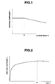
- Fig. 1 shows a relationship between a sliding speed and a friction coefficient of a friction material employed as the brake lining of a vehicular brake device in accordance with the present invention.
- sliding speed V is a speed of a rotational member (disc rotor or brake drum) in a case that the rotational member slides on the brake lining (friction element) while being forced into frictional contact with the brake lining.
- the friction material employed as the brake lining has a characteristic that the friction coefficient ⁇ is kept at about the same value when sliding speed V is within a range from 0 to a predetermined value V C , and friction coefficient ⁇ decreases according to an increase of sliding speed V when sliding speed V is greater than the predetermined value V C .
- the predetermined value V C is a speed at which the brake device generates a self-excited vibration.
- Fig. 2 shows a graph representative of a change of the friction coefficient of the friction material of the brake lining according to the elapsed time in the event that the braking is executed by applying a constant braking depressing force to the brake pedal, in a case that the brake device employs the friction material of Fig. 1 into the brake lining.
- friction coefficient ⁇ suddenly rises just after the driver depresses the brake pedal, and friction coefficient then slowly rises according to the elapse time until the elapsed time becomes a time T C . Thereafter, friction coefficient ⁇ maintains about the same value.
- time T C is a time when sliding speed V takes the predetermined value V C .
- Fig. 3 is a graph showing changes of vehicle speed V S and sliding speed V according to the elapsed time under the condition of Fig. 2.
- vehicle speed V S decreases according to the elapsed time in the curve shown in Fig. 3.
- sliding speed V decreases while vibrating with an amplitude ⁇ V.
- V S - ⁇ V a difference between vehicle speed V S and amplitude ⁇ V becomes smaller than zero (V S - ⁇ V ⁇ 0)
- V S - ⁇ V ⁇ 0 the self-excited vibration generated in the brake device increases, and the noise due to this self-excited vibration also increases.
- friction coefficient ⁇ is kept almost at a constant value so as to suppress the self-excited vibration of the brake device and to prevent the generation of the noise due to the self-excited vibration, after the moment when the difference V S - ⁇ V becomes zero, that is, when the vehicle speed V S reaches the predetermined value V C .
- Fig. 4 is a graph showing changes of braking energy E according to the elapsed time and to a change of temperature, and a change of friction coefficient ⁇ according to a change of temperature, in addition to the characteristic curve in Fig. 2.
- braking energy E is a total quantity of energy absorbed by the brake device during the elapsed time.
- Fig. 4 clearly shows that these relationships are interconnected with each other. That is, the relationship between braking energy E and friction coefficient ⁇ of the friction material of the brake lining may be designed such that friction coefficient ⁇ increases until braking energy E reaches a predetermined value, and that friction coefficient ⁇ becomes constant when braking energy E becomes greater than the predetermined value.
- the brake lining (friction member) according to the present invention employs a single kind of the friction material
- the aimed characteristic of the friction member may be obtained by combining the plural kind of friction materials which performs different characteristics, respectively.
- Fig. 5A shows a characteristic of a first friction material A wherein friction coefficient ⁇ decreases according to the increase of sliding speed V. More specifically, friction coefficient ⁇ increases according to the deceleration of the vehicle.
- Fig. 5B shows a characteristic of a second friction material B wherein friction coefficient ⁇ takes about the same value when sliding speed V is greater than a predetermined value, and friction coefficient ⁇ increases according to the increase of sliding speed V when sliding speed V is smaller than the predetermined value.
- first friction material A and second friction material B By combining first friction material A and second friction material B, the characteristic shown by a continuous line in Fig. 5C is obtained. More specifically, the combination of first and second friction materials A and B performs the characteristic that friction coefficient ⁇ takes about the same value when sliding speed V ranges from 0 to the predetermined value V C , and friction coefficient ⁇ decreases according to the increase of sliding speed V when sliding speed V is greater than or equal to the predetermined value V C . It will be understood that it is necessary to select the friction materials so that the characteristic curves of the first and second friction materials intersect at the predetermined value V C .
- Figs. 6A through 6D show various arrangements of the above-discussed first and second friction materials A and B employed as a brake lining (brake pad) of a disc brake.
- Fig. 6A shows an arrangement of a brake pad 10 of the disc brake, wherein brake pad 10 is constituted by first and second friction materials A and B.
- Brake pad 10 is constructed by arranging a first friction member 11 of first friction material A and a second friction member 12 of second friction material B side by side while having a clearance 13 between first and second friction members 11 and 12.
- the disc brake employing this brake pad 10 performs the characteristic shown by Fig. 5C.
- Fig. 6B shows another arrangement of first and second friction materials A and B as a brake pad 20 of the disc brake in accordance with the present invention.
- Brake pad 20 is constructed by arranging a first friction member 21 of first friction material A and a second friction member 22 of second friction material B side by side, as is similar to the arrangement of Fig. 6A although there is no clearance between first and second friction members 21 and 22. That is, first and second friction members 21 and 22 are integrally arranged. By this arrangement, the desired characteristic of brake pad 20 is further firmly obtained.
- Fig. 6C shows another arrangement of first and second friction materials A and B as a brake pad 30 of the disc brake in accordance with the present invention.
- Brake pad 30 is constructed by arranging two friction members 31 and 32 of first friction material A and two friction members 33 and 34 of second friction material B checkerwise as is clearly shown in Fig. 6C.
- Fig. 6D shows a further another arrangement of first and second friction materials A and B of a brake pad 40 of the disc brake in accordance with the present invention.
- Brake pad 40 of this arrangement of Fig. 6D is constructed by two friction members 41 and 42 of the first friction material A and two friction members 43 and 44 of the second friction material B by alternately arranging two kinds of friction material. More specifically, as is clearly shown in Fig. 6D, friction members 41 through 44 are arranged in the order of 41, 43, 42 and 44. By this arrangement, the desired characteristic of the brake pad is further firmly obtained.
- each brake device When the thus arranged brake pads particularly brake pads 30 are employed in the brake device, a pair of brake pads 30A and 30B are used in each brake device for each wheel. Brake pads 30A and 30B are positioned on the two sides of a disc rotor (rotational member) 50. Two brake pads 30A and 30B are arranged such that the friction members of the same friction material are oppositely disposed as shown in Fig. 7. By this arrangement of brake pads 30A and 30B onto respective shoes of each brake device, each brake device properly executes the aimed braking operation. If the different friction materials A and B are oppositely disposed in the respective brake pads, there is a possibility that undesired vibration is generated by the unbalance of the friction force and that the brake lining is worn on one side.
- first friction material 31A of brake pad 30A and the first friction material 31B of brake pad 30B are oppositely disposed while disc rotor 50 is located between brake pads 30A and 30B.
- First friction material 32A of brake pad 30A and first friction material 32B of brake pad 30B are oppositely disposed while disc rotor 50 is located between brake pads 30A and 30B.
- Second friction material 33A of brake pad 30A and second friction material 33B of brake pad 30B are oppositely disposed while disc rotor 50 is located between brake pads 30A and 30B.
- Second friction material 34A of brake pad 30A and first friction material 34B of brake pad 30B are oppositely disposed while disc rotor 50 is located between brake pads 30A and 30B. That is, friction materials A and B of brake pads 30a and 30B are put in a same-material-opposed arrangement where the same material portions of brake pad 30A are faced with the same material portions of brake pad 30B.
- disc rotor 50 When the braking is not executed or when the braking has just been finished, disc rotor 50 is positioned at a neutral position between two brake pads 30A and 30B as shown in Fig. 8A. However, if the different friction materials are oppositely disposed, disc rotor 50 may be deformed by biased heating due to the unbalance of the friction force, as shown in Fig. 8B, and consequently there is a possibility that the braking device cannot perform the desired braking characteristic in the braking operation. In order to avoid such a problem, the friction materials are arranged as shown in Fig. 7.
- the present invention is not limited to the above-discussed arrangements, and the brake pads (brake linings) may be constructed by combining three or more kinds of friction materials. Further, although the embodiment according to the present invention have been shown and described such that the friction material having the desired characteristic is adapted to the brake pad of the disc brake, it will be understood that the friction material may be adapted to a brake shoe of a drum brake.
Landscapes
- Engineering & Computer Science (AREA)
- General Engineering & Computer Science (AREA)
- Mechanical Engineering (AREA)
- Braking Arrangements (AREA)
Abstract
Description
Claims (9)
- A brake lining (10, 20, 30, 40) of a vehicular brake device, the brake device executing a braking operation by forcing the brake lining into friction contact with a rotational member, the brake lining comprising:a friction material (A and B) having a characteristic that a friction coefficient of the friction material decreases according to an increase of a sliding speed between the brake lining and the rotational member when the sliding speed is greater than or equal to a predetermined speed during the braking operation, and the friction coefficient is substantially constant when the sliding speed is smaller than the predetermined speed.
- The brake lining as claimed in claim 1, wherein the predetermined speed is a speed at which a self-excited vibration of the brake device is generated.
- The brake lining as claimed in one of claims 1 and 2, wherein a desired characteristic of the friction material is achieved by a combination of at least two frictional materials which are different in the characteristic of the friction coefficient relative to the sliding speed.
- The brake lining as claimed in claim 3, wherein the at least two friction materials are arranged such that the rotational member always frictionally slides on the brake lining when the braking operation is being executed.
- The brake lining as claimed in one of claims 3 and 4, wherein the brake includes a disc brake which produces a braking force by a clamping action of a pair of the brake linings to the rotational member.
- The brake lining as claimed in claim 5, wherein first and second friction materials are formed into first friction members and second fiction members, respectively, and the first and second friction members are arranged side by side alternately.
- The brake lining as claimed in claim 5, wherein first and second friction materials are formed into first friction members and second fiction members, respectively, and the first and second friction members are arranged checkerwise.
- The brake lining as claimed in one of claims 1 and 2, wherein the friction material is produced by a combination of first and second friction materials, the first material having a characteristic that a friction coefficient of the first friction material decreases according to an increase of the sliding speed, the second friction material having a characteristic that a friction coefficient of the second friction material takes about the same value when sliding speed is greater than a predetermined value and the friction coefficient of the second friction material increases according to the increase of the sliding speed when the sliding speed is smaller than the predetermined value.
- A disc brake of a vehicle, comprising:a disc rotor (50); anda pair of bake pads (30A and 30B) forced into fiction contact with the disc rotor, the brake pads being constructed by a friction material which has a characteristic that a friction coefficient of the friction material decreases according to an increase of a sliding speed between the brake lining and the rotational member when the sliding speed is greater than or equal to a predetermined speed during the braking operation, and the friction coefficient is substantially constant when the sliding speed is smaller than the predetermined speed.
Applications Claiming Priority (2)
| Application Number | Priority Date | Filing Date | Title |
|---|---|---|---|
| JP2001374477 | 2001-12-07 | ||
| JP2001374477A JP3744416B2 (en) | 2001-12-07 | 2001-12-07 | Friction material for brake equipment |
Publications (3)
| Publication Number | Publication Date |
|---|---|
| EP1318320A2 true EP1318320A2 (en) | 2003-06-11 |
| EP1318320A3 EP1318320A3 (en) | 2003-12-17 |
| EP1318320B1 EP1318320B1 (en) | 2008-07-02 |
Family
ID=19183032
Family Applications (1)
| Application Number | Title | Priority Date | Filing Date |
|---|---|---|---|
| EP02257760A Expired - Lifetime EP1318320B1 (en) | 2001-12-07 | 2002-11-08 | Brake lining of brake device |
Country Status (6)
| Country | Link |
|---|---|
| US (1) | US6672433B2 (en) |
| EP (1) | EP1318320B1 (en) |
| JP (1) | JP3744416B2 (en) |
| KR (1) | KR100484470B1 (en) |
| CN (1) | CN1226539C (en) |
| DE (1) | DE60227336D1 (en) |
Families Citing this family (17)
| Publication number | Priority date | Publication date | Assignee | Title |
|---|---|---|---|---|
| SE522456C2 (en) * | 2000-09-28 | 2004-02-10 | Volvo Lastvagnar Ab | Brake means and writing brake and drum brake including such means |
| JP2004125081A (en) * | 2002-10-03 | 2004-04-22 | Advics:Kk | Disc brake pad |
| US7097009B2 (en) * | 2003-10-30 | 2006-08-29 | Akebono Corporation (North America) | Friction material configuration and method of manufacture for brake applications |
| JP2005141865A (en) * | 2003-11-07 | 2005-06-02 | Toyota Motor Corp | High density recording medium |
| JP4379184B2 (en) | 2004-04-08 | 2009-12-09 | 日産自動車株式会社 | Brake control device for vehicle |
| JP2006112506A (en) * | 2004-10-14 | 2006-04-27 | Advics:Kk | Disc brake |
| DE102007000276A1 (en) * | 2006-05-18 | 2007-11-22 | Advics Co., Ltd., Kariya | Hybrid brake pads for disc brakes |
| US20080011562A1 (en) * | 2006-07-11 | 2008-01-17 | Hilbrandt William P | Multiple layer friction material brake pad |
| KR101041031B1 (en) | 2008-12-23 | 2011-06-15 | 고려대학교 산학협력단 | Fused friction material and vehicle brake including the same |
| US20110272222A1 (en) * | 2010-05-07 | 2011-11-10 | Brake Parts, Inc. | Hybrid brake pad |
| GB201218472D0 (en) | 2012-10-15 | 2012-11-28 | Jaguar Cars | A brake pad,a brake system and a vehicle |
| US10125836B2 (en) * | 2015-06-10 | 2018-11-13 | Nucap Industries Inc. | Brake pad with preformed multi-layer friction pad and shim |
| DE102015226344A1 (en) | 2015-12-21 | 2017-06-22 | Knorr-Bremse Systeme für Schienenfahrzeuge GmbH | Brake control for rail vehicles with adaptive lining characteristic |
| EP3450789B1 (en) | 2017-08-31 | 2021-05-26 | Meritor Heavy Vehicle Braking Systems (UK) Limited | A disc brake |
| US11655867B2 (en) * | 2018-08-21 | 2023-05-23 | Akebono Brake Industry Co., Ltd | Disc brake system |
| WO2022159084A1 (en) | 2021-01-20 | 2022-07-28 | Volvo Truck Corporation | Disc brake system and method for braking a vehicle |
| CN117651811A (en) | 2021-07-08 | 2024-03-05 | 日立安斯泰莫株式会社 | Drum brakes and brake components |
Family Cites Families (19)
| Publication number | Priority date | Publication date | Assignee | Title |
|---|---|---|---|---|
| US3791493A (en) * | 1970-12-05 | 1974-02-12 | Nippon Carbon Co Ltd | Friction elements for braking rotary bodies |
| JPS5833833U (en) * | 1981-08-28 | 1983-03-05 | トヨタ自動車株式会社 | Disc brake pad structure with caliper |
| JPS63190942A (en) * | 1987-02-04 | 1988-08-08 | Uedasa Chuzosho:Kk | Variable-friction coefficient brake shoe |
| JPH0312629A (en) * | 1989-06-09 | 1991-01-21 | Omron Corp | Collating system |
| US4994506A (en) * | 1989-08-31 | 1991-02-19 | Redco N.V. | Brake linings |
| US5268398A (en) * | 1989-09-01 | 1993-12-07 | Sumitomo Electric Industries, Ltd. | Friction material and method of manufacturing such material |
| US5048654A (en) * | 1990-07-20 | 1991-09-17 | Borg-Warner Automotive, Inc. | Ceramic clutch separator plates |
| DE4140220A1 (en) * | 1991-12-06 | 1993-06-09 | Alfred Teves Gmbh, 6000 Frankfurt, De | Brake disc pads - with concentric friction areas having increasing friction coefft. towards centre of disc to ensure uniform heating during braking |
| JPH05306725A (en) * | 1992-04-30 | 1993-11-19 | Isuzu Motors Ltd | Brake shoe for drum brake |
| KR970046054A (en) * | 1995-12-30 | 1997-07-26 | 한승준 | Brake of a car |
| JPH1089391A (en) * | 1996-09-19 | 1998-04-07 | Kayaba Ind Co Ltd | Friction pad for brake |
| KR19980054339U (en) * | 1996-12-31 | 1998-10-07 | 박병재 | Brake Pads for Caliper Brake |
| JPH10318307A (en) * | 1997-05-22 | 1998-12-04 | Toyota Motor Corp | Disc brake pad |
| JP3948844B2 (en) * | 1998-06-12 | 2007-07-25 | トヨタ自動車株式会社 | Wet friction material |
| JP2000063803A (en) * | 1998-08-19 | 2000-02-29 | Nsk Warner Kk | Wet type friction material |
| JP4249306B2 (en) * | 1998-11-16 | 2009-04-02 | Nskワーナー株式会社 | Wet friction material |
| JP2001247852A (en) * | 2000-03-03 | 2001-09-14 | Nisshinbo Ind Inc | Non-asbestos friction material |
| SE522456C2 (en) * | 2000-09-28 | 2004-02-10 | Volvo Lastvagnar Ab | Brake means and writing brake and drum brake including such means |
| US6499571B1 (en) * | 2001-06-07 | 2002-12-31 | Meritor Heavy Vehicle Technology, Llc | Brake pad with improved green performance |
-
2001
- 2001-12-07 JP JP2001374477A patent/JP3744416B2/en not_active Expired - Fee Related
-
2002
- 2002-11-08 EP EP02257760A patent/EP1318320B1/en not_active Expired - Lifetime
- 2002-11-08 DE DE60227336T patent/DE60227336D1/en not_active Expired - Fee Related
- 2002-11-08 US US10/290,248 patent/US6672433B2/en not_active Expired - Fee Related
- 2002-12-06 KR KR10-2002-0077130A patent/KR100484470B1/en not_active Expired - Fee Related
- 2002-12-06 CN CNB021545677A patent/CN1226539C/en not_active Expired - Fee Related
Also Published As
| Publication number | Publication date |
|---|---|
| KR20030047779A (en) | 2003-06-18 |
| US20030106749A1 (en) | 2003-06-12 |
| EP1318320B1 (en) | 2008-07-02 |
| CN1226539C (en) | 2005-11-09 |
| DE60227336D1 (en) | 2008-08-14 |
| KR100484470B1 (en) | 2005-04-20 |
| JP3744416B2 (en) | 2006-02-08 |
| US6672433B2 (en) | 2004-01-06 |
| CN1424211A (en) | 2003-06-18 |
| JP2003172385A (en) | 2003-06-20 |
| EP1318320A3 (en) | 2003-12-17 |
Similar Documents
| Publication | Publication Date | Title |
|---|---|---|
| US6672433B2 (en) | Brake lining of brake device | |
| KR100477779B1 (en) | Disk brake and brake shoe set for a disk brake | |
| EP0971146B1 (en) | Disc brake | |
| US5381875A (en) | Disc brake assembly | |
| JPH09229112A (en) | Disc brake | |
| JPH07103269A (en) | Disc brake device with shim | |
| JP2010048363A (en) | Brake caliper | |
| JPH0645712Y2 (en) | Disc brake | |
| US6206146B1 (en) | Disc brake assembly | |
| JP3209688B2 (en) | Disc brake device | |
| JPH0814280A (en) | Disc brake | |
| KR20220053371A (en) | Disk break apparatus | |
| JP2587544Y2 (en) | Pad for disc brake | |
| JPH0247775Y2 (en) | ||
| JPH09196092A (en) | Disc brake device | |
| JPH08135698A (en) | Brake pad for disc brake device | |
| JP3629859B2 (en) | Drum brake | |
| JPH0529536Y2 (en) | ||
| KR0163226B1 (en) | Drum brake | |
| JPH07208516A (en) | Disc brake shim | |
| KR100534255B1 (en) | Brake-shoe Structure of Drum Brake | |
| KR100779485B1 (en) | Disc brake | |
| JPS5947534A (en) | Brake pad set spring | |
| JPH10331881A (en) | Disc brake | |
| JPH09112599A (en) | Disc brake |
Legal Events
| Date | Code | Title | Description |
|---|---|---|---|
| PUAI | Public reference made under article 153(3) epc to a published international application that has entered the european phase |
Free format text: ORIGINAL CODE: 0009012 |
|
| 17P | Request for examination filed |
Effective date: 20021202 |
|
| AK | Designated contracting states |
Designated state(s): AT BE BG CH CY CZ DE DK EE ES FI FR GB GR IE IT LI LU MC NL PT SE SK TR |
|
| AX | Request for extension of the european patent |
Extension state: AL LT LV MK RO SI |
|
| PUAL | Search report despatched |
Free format text: ORIGINAL CODE: 0009013 |
|
| AK | Designated contracting states |
Kind code of ref document: A3 Designated state(s): AT BE BG CH CY CZ DE DK EE ES FI FR GB GR IE IT LI LU MC NL PT SE SK TR |
|
| AX | Request for extension of the european patent |
Extension state: AL LT LV MK RO SI |
|
| RIC1 | Information provided on ipc code assigned before grant |
Ipc: 7F 16D 69/02 B Ipc: 7F 16D 69/00 B Ipc: 7F 16D 65/00 A |
|
| AKX | Designation fees paid |
Designated state(s): DE FR GB |
|
| 17Q | First examination report despatched |
Effective date: 20041013 |
|
| GRAP | Despatch of communication of intention to grant a patent |
Free format text: ORIGINAL CODE: EPIDOSNIGR1 |
|
| GRAS | Grant fee paid |
Free format text: ORIGINAL CODE: EPIDOSNIGR3 |
|
| GRAA | (expected) grant |
Free format text: ORIGINAL CODE: 0009210 |
|
| AK | Designated contracting states |
Kind code of ref document: B1 Designated state(s): DE FR GB |
|
| REG | Reference to a national code |
Ref country code: GB Ref legal event code: FG4D |
|
| REF | Corresponds to: |
Ref document number: 60227336 Country of ref document: DE Date of ref document: 20080814 Kind code of ref document: P |
|
| PGFP | Annual fee paid to national office [announced via postgrant information from national office to epo] |
Ref country code: DE Payment date: 20081107 Year of fee payment: 7 |
|
| PGFP | Annual fee paid to national office [announced via postgrant information from national office to epo] |
Ref country code: FR Payment date: 20081112 Year of fee payment: 7 |
|
| PLBE | No opposition filed within time limit |
Free format text: ORIGINAL CODE: 0009261 |
|
| STAA | Information on the status of an ep patent application or granted ep patent |
Free format text: STATUS: NO OPPOSITION FILED WITHIN TIME LIMIT |
|
| 26N | No opposition filed |
Effective date: 20090403 |
|
| PGFP | Annual fee paid to national office [announced via postgrant information from national office to epo] |
Ref country code: GB Payment date: 20081105 Year of fee payment: 7 |
|
| GBPC | Gb: european patent ceased through non-payment of renewal fee |
Effective date: 20091108 |
|
| REG | Reference to a national code |
Ref country code: FR Ref legal event code: ST Effective date: 20100730 |
|
| PG25 | Lapsed in a contracting state [announced via postgrant information from national office to epo] |
Ref country code: FR Free format text: LAPSE BECAUSE OF NON-PAYMENT OF DUE FEES Effective date: 20091130 |
|
| PG25 | Lapsed in a contracting state [announced via postgrant information from national office to epo] |
Ref country code: DE Free format text: LAPSE BECAUSE OF NON-PAYMENT OF DUE FEES Effective date: 20100601 |
|
| PG25 | Lapsed in a contracting state [announced via postgrant information from national office to epo] |
Ref country code: GB Free format text: LAPSE BECAUSE OF NON-PAYMENT OF DUE FEES Effective date: 20091108 |