TECHNICAL FIELD
-
The present invention relates to an engine control
system of an internal combustion engine with both a
variable compression ratio mechanism and an exhaust-gas
recirculation (EGR) control system, and specifically to
techniques for enhancing fuel economy and engine
performance under a part load condition of a
spark-ignition internal combustion engine.
BACKGROUND ART
-
In recent years, there have been proposed and
developed various reciprocating internal combustion
engines equipped with a variable compression ratio
mechanism enabling a nominal compression ratio or a
geometrical or mechanical compression ratio denoted by
Greek letter ε (epsilon) to be continuously varied
depending on engine operating conditions. One such
variable compression ratio mechanism has been disclosed
in Japanese Patent Provisional Publication No.2000-73804
(hereinafter is referred to as "JP2000-73804"). In the
internal combustion engine of JP2000-73804, a multi-link
type piston-crank mechanism is used as a variable
compression ratio mechanism. Under a part load condition,
compression ratio ε is adjusted to a high compression
ratio in order to enhance a thermal efficiency. In
contrast, at high loads, compression ratio ε is set or
adjusted to as high a ratio as possible, taking into account
the frequency of detonation or knock. On the other hand,
Japanese Patent Provisional Publication No. 7-259655
(hereinafter is referred to as "JP7-259655") discloses
a variable compression ratio engine capable of switching
between a standard Otto-cycle operating mode and either
one of a so-called early intake-valve closing Miller-cycle
operating mode at which the intake valve is closed at
approximately 90 degrees of crankangle before BDC on the
intake stroke and a so-called late intake-valve closing
Miller-cycle operating mode at which the intake valve
is closed approximately 90 degrees of crankangle after
BDC on the intake stroke. The early intake-valve closing
Miller-cycle operating mode and late intake-valve closing
Miller-cycle operating mode both contribute to a reduction
in effective compression ratio. JP7-259655 teaches
lowering an exhaust-gas recirculation rate by switching
from the standard Otto-cycle operating mode to the
Miller-cycle operating mode. That is, JP7-259655
utilizes switching between the standard Otto-cycle
operating mode and the Miller-cycle operating mode instead
of using a variable compression ratio mechanism (a
multi-link type piston-crank mechanism) as disclosed in
JP2000-73804 that variably controls a mechanical
compression ratio ε.
SUMMARY OF THE INVENTION
-
In the spark-ignition internal combustion engine
disclosed in JP2000-73804 capable of variably controlling
a nominal compression ratio (or a mechanical compression
ratio ε), it is possible to enhance the thermal efficiency
by adjusting compression ratio ε to as high a ratio as
possible under a part load condition. However,
adjustment of the compression ratio to high results in
a rise in combustion temperature, thereby increasing
cooling loss. Thus, during part loads, a remarkable
improvement in fuel economy cannot be achieved, because,
on the one hand, the fuel consumption rate tends to reduce
due to the enhanced thermal efficiency, and, on the other
hand, the fuel consumption rate tends to increase due
to the increased cooling loss. In particular, in case
of a spark-ignition internal combustion engine employing
a variable compression ratio mechanism that mechanical
compression ratio ε is variably adjusted by changing a
top dead center (TDC) position of a piston stroke
characteristic containing both the TDC position and BDC
position with the compression ratio adjusted to high,
the TDC position tends to extremely approach to the
cylinder head in such a manner as to form an excessively
flat combustion chamber. Such an excessively flat shape
of combustion chamber leads to an increase in a so-called
S/V ratio of the surface area existing within the
combustion chamber to the volume existing within the
combustion chamber, thus increasing cooling loss. As is
generally known, in order to improve fuel economy under
a part load condition, it is very effective to add exhaust
gases recirculated. Such EGR addition contributes to a
reduction in cooing loss but leads to the problem of slow
combustion velocities. That is, combustion begins at a
late timing after TDC. Such a retardation in combustion
results in increased time loss. In particular, during
the part-load condition, there is a tendency for
combustion to occur slowly, and therefore the thermal
efficiency tends to remarkably reduce due to the increased
time loss. Additionally, a large amount of exhaust gases
recirculated causes unstable combustion.
-
In the same manner, the previously-noted
Miller-cycle, employing early intake-valve closing,
contributes to a reduction in pumping loss and cooling
loss. However, the early intake-valve closing
Miller-cycle operating mode also leads to the problem
of slow combustion velocities, that is, the increased
time loss.
-
Accordingly, it is an object of the invention to
provide an engine control system of an internal combustion
engine with a variable compression ratio mechanism and
an exhaust-gas recirculation control system, which avoids
the aforementioned disadvantages.
-
It is another object of the invention to avoid
problems of increased time loss and unstable combustion,
occurring owing to EGR and early intake-valve closing,
by properly setting a piston velocity characteristic
(linkage layout) of a multi-link type piston-crank
mechanism constructing a variable compression ratio
mechanism, and to remarkably improve fuel economy under
a part load condition by way of an optimal combination
of several ways to improve fuel economy, namely
compression ratio control, EGR control, engine valve
timing control, and improved linkage layout of the
multi-link type piston-crank mechanism.
-
It is a further object of the invention to provide
an internal combustion engine with a variable compression
ratio mechanism and an exhaust-gas recirculation control
system, capable of effectively properly using internal
EGR and/or external EGR.
-
In order to accomplish the aforementioned and other
objects of the present invention, an engine control system
for an internal combustion engine comprises a variable
compression ratio mechanism comprising a multi-link type
piston-crank mechanism having a plurality of links and
enabling a compression ratio of the engine to be varied
by changing a piston stroke characteristic by way of a
change in an attitude of a part of the links, an exhaust-gas
recirculation system enabling at least one of external
EGR and internal EGR to be controlled, the links of the
multi-link type piston-crank mechanism being laid out,
so that a piston velocity near top dead center, obtained
by the multi-link type piston-crank mechanism, is slower
than a piston velocity near top dead center, obtained
by a single-link type piston-crank mechanism having at
least the same piston stroke as the multi-link type
piston-crank mechanism, during a part load condition of
the engine, the variable compression ratio mechanism
controlling the compression ratio to a predetermined high
compression ratio, and during the part load condition,
the exhaust-gas recirculation system increasing
exhaust-gas recirculation.
-
According to another aspect of the invention, an
engine control system for an internal combustion engine
comprises a variable compression ratio mechanism
comprising a multi-link type piston-crank mechanism
having a plurality of links and enabling a compression
ratio of the engine to be varied by changing a piston
stroke characteristic by way of a change in an attitude
of apart of the links, an exhaust-gas recirculation system
enabling at least one of external EGR and internal EGR
to be controlled, the links of the multi-link type
piston-crank mechanism being laid out, so that a maximum
piston acceleration near top dead center, obtained by
the multi-link type piston-crank mechanism, is less than
a maximum piston acceleration near bottom dead center,
obtained by the multi-link type piston-crank mechanism,
during a part load condition of the engine, the variable
compression ratio mechanism controlling the compression
ratio to a predetermined high compression ratio, and
during the part load condition, the exhaust-gas
recirculation system increasing exhaust-gas
recirculation.
-
According to a further aspect of the invention, an
engine control system for an internal combustion engine
comprises variable compression ratio means comprising
a multi-link type piston-crank mechanism having a
plurality of links that enable a compression ratio of
the engine to be varied by changing a piston stroke
characteristic by way of a change in an attitude of a
part of the links, exhaust-gas recirculation means for
enabling at least one of external EGR and internal EGR
to be controlled, the links of the multi-link type
piston-crank mechanism being laid out, so that a piston
velocity near top dead center, obtained by the multi-link
type piston-crank mechanism, is slower than a piston
velocity near top dead center, obtained by a single-link
type piston-crank mechanism having at least the same
piston stroke as the multi-link type piston-crank
mechanism, during a part load condition of the engine,
the variable compression ratio means controlling the
compression ratio to a predetermined high compression
ratio, and during the part load condition, the exhaust-gas
recirculation means increasing exhaust-gas
recirculation. More preferably, the links of the
multi-link type piston-crank mechanism may be laid out,
so that a maximum piston acceleration near top dead center,
obtained by the multi-link type piston-crank mechanism,
is less than a maximum piston acceleration near bottom
dead center, obtained by the multi-link type piston-crank
mechanism.
-
The other objects and features of this invention
will become understood from the following description
with reference to the accompanying drawings.
BRIEF DESCRIPTION OF THE DRAWINGS
-
- Fig. 1 is a system block diagram illustrating the
construction of an internal combustion engine of the
embodiment, employing a variable valve operating
mechanism and a variable compression ratio mechanism.
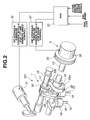
- Fig. 2 is a perspective view illustrating the
detailed structure of the variable valve operating
mechanism containing both a variable lift and working
angle control mechanism and a variable phase control
mechanism.
- Fig. 3A is an explanatory view showing the essential
linkage and valve operating mechanism layout of the
embodiment under a zero-lift condition, as viewed from
the axial direction of the crankshaft.
- Fig. 3B is an explanatory view showing the essential
linkage and valve operating mechanism layout of the
embodiment under a full-lift condition, as viewed from
the axial direction of the crankshaft.
- Fig. 4 shows lift and working angle characteristic
curves given by the variable lift and working angle control
mechanism of Fig. 2.
- Fig. 5 shows phase-change characteristic curves for
a phase of working angle that means an angular phase at
the maximum valve lift point, often called "central angle
", given by the variable phase control mechanism of Fig.
2.
- Fig. 6 is a front elevation view illustrating the
essential linkage layout of the multi-link type
reciprocating engine of the embodiment, as viewed from
the axial direction of the crankshaft.
- Fig. 7A is a characteristic curve showing a piston
stroke characteristic obtained by the multi-link type
piston-crank mechanism incorporated in the reciprocating
engine of the embodiment and serving as the variable
compression ratio mechanism.
- Fig. 7B is a characteristic curve showing a piston
velocity characteristic obtained by the multi-link type
piston-crank mechanism incorporated in the reciprocating
engine of the embodiment and serving as the variable
compression ratio mechanism.
- Fig. 8A is an explanatory view illustrating the
linkage layout of the variable compression ratio mechanism
(the multi-link type piston-crank mechanism) in a high
compression ratio operating mode, as viewed from the axial
direction of the crankshaft.
- Fig. 8B is an explanatory view illustrating the
linkage layout of the variable compression ratio mechanism
(the multi-link type piston-crank mechanism) in a low
compression ratio operating mode, as viewed from the axial
direction of the crankshaft.
- Fig. 9 shows a general control characteristic for
mechanical compression ratio ε depending on engine
operating conditions.
- Fig. 10 is an explanatory view showing a valve lift
characteristic (intake valve open timing IVO, intake valve
closure timing IVC, working angle EA, central angle )
of the intake valve, performed by the variable valve
operating mechanism incorporated in the multi-link type
reciprocating engine of the embodiment, under various
engine/vehicle operating conditions, that is, during
idling, at part load, during acceleration, at full
throttle and low speed, and at full throttle and high
speed.
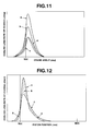
- Fig. 11 shows four crankangle versus cooling-loss
rate-of-change characteristic curves a, b, c and d under
a proper combination of (1) adjustment of mechanical
compression ratio ε to high, (2) early intake-valve
closing, (3) adequate EGR, and (4) reduced piston velocity
near TDC.
- Fig. 12 shows piston position versus cooling-loss
rate-of-change characteristic curves e and f,
respectively obtained by the multi-link type
reciprocating engine of the embodiment and a single-link
type reciprocating engine.
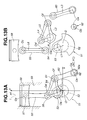
- Fig. 13A shows an example of the linkage layout of
the multi-link type reciprocating engine that the
reciprocating motion of the piston is approximate to a
simple harmonic motion.
- Fig. 13B is a disassembled view of the linkage of
the multi-link type reciprocating engine shown in Fig.
13A.
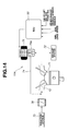
- Fig. 14 is a system block diagram of an engine control
system equipped with an EGR control system.
- Figs. 15A, 15B, 15C, 15D, and 15E are time charts
showing how the fluctuation rate of combustion pressure
Pi, cooling loss, pumping loss, and fuel consumption rate
are affected by variations in mechanical compression ratio
ε in presence of EGR.
- Figs. 16A, 16B, 16C, 16D, and 16E are time charts
showing how the fluctuation rate of combustion pressure
Pi, cooling loss, pumping loss, and fuel consumption rate
are affected by variations in piston velocity near TDC
in presence of EGR.
- Fig. 17 is an explanatory view showing a valve lift
characteristic (IVO, IVC, EA, EVO) of engine valves,
performed by the variable valve operating mechanism
incorporated in the multi-link type reciprocating engine
of the embodiment, under various engine/vehicle operating
conditions, in the presence or absence of external EGR
and/or internal EGR.
- Fig. 18 is a characteristic map showing the
relationship between a valve lift characteristic (valve
lift and working angle) and an external EGR execution
zone under various engine/vehicle operating conditions.
- Fig. 19 shows a control characteristic for mechanical
compression ratio ε variably controlled by the variable
compression ratio mechanism incorporated in the
multi-link type reciprocating engine of the embodiment,
depending on engine operating conditions.
- Figs. 20A, 20B, 20C, 20D, 20E, and 20F are time charts
showing variations in the EGR valve opening Ae, throttle
opening TVO, intake-valve working angle EA, intake-valve
central angle , intake valve open timing IVO, and intake
valve closure timing IVC, when accelerating from an idling
state to a middle acceleration rate after engine warm-up.
- Figs. 21A, 21B, 21C, 21D, 21E, and 21F are time charts
showing variations in the EGR valve opening Ae, throttle
opening TVO, intake-valve working angle EA, intake-valve
central angle , intake valve open timing IVO, and intake
valve closure timing IVC, when moderately accelerating
from an idling state to a slight acceleration rate after
engine warm-up.
- Figs. 22A, 22B, 22C, 22D, 22E, and 22F are time charts
showing variations in the EGR valve opening Ae, throttle
opening TVO, intake-valve working angle EA, intake-valve
central angle , intake valve open timing IVO, and intake
valve closure timing IVC, when accelerating from an idling
state to a middle acceleration rate with a cold engine.
-
DESCRIPTION OF THE PREFERRED EMBODIMENTS
-
Referring now to the drawings, particularly to Fig.
1, the integrated engine control system of the invention
is exemplified in an automotive spark-ignition
multi-cylinder gasoline engine. The integrated engine
control system of the embodiment has three different
control mechanisms, namely a variable valve operating
mechanism 101, a variable compression ratio mechanism
102, and an electronic ignition-timing control system
(an ignition timing advancer) 103. Variable valve
operating mechanism 101 is applied to an intake-port valve
of engine valves, and provided to variably control an
intake valve open timing IVO and an intake valve closure
timing IVC, depending on engine operating conditions.
Variable compression ratio mechanism 102 is provided to
variably control a nominal compression ratio or a
geometrical or mechanical compression ratio ε depending
on engine operating conditions. Ignition timing advancer
103 is provided to electronically retard or advance the
timing of spark. As shown in Figs . 1 and 2, variable valve
operating mechanism 101 is comprised of a variable lift
and working angle control mechanism 1 and a variable phase
control mechanism 2 combined to each other. Variable lift
and working angle control mechanism 1 functions to change
(increase or decrease) both a valve lift and a working
angle EA of an intake valve 12, depending on engine/vehicle
operating conditions. Variable phase control mechanism
2 functions to change (advance or retard) the angular
phase at the maximum valve lift point (at the central
angle ). By means of variable valve operating mechanism
101, constructed by variable lift and working angle
control mechanism 1 and variable phase control mechanism
2 combined to each other, it is possible to arbitrarily
change intake valve open timing IVO and intake valve
closure timing IVC independently of each other. In the
shown embodiment, an exhaust valve open timing EVO and
an exhaust valve closure timing EVC are both fixed. Thus,
it is possible to change the magnitude of the valve overlap
from intake valve open timing IVO to exhaust valve closure
timing EVC by changing intake valve open timing IVO. In
addition to the above, by adjusting intake valve closure
timing IVC to a timing before the BDC position on intake
stroke, it is possible to change the actual compression
ratio (an effective compression ratio ε' described later) .
Additionally, the system of the embodiment utilizes
internal EGR as well as external EGR. The external EGR
(which will be fully described later in reference to the
system block diagram shown in Fig. 14) means exhaust-gas
recirculation that is achieved by way of a conventional
EGR system whose EGR control valve allows part of exhaust
gases to enter the intake manifold (the intake port side).
On the other hand, the internal EGR means exhaust gas
or combustion gas recirculated from the exhaust port
through the engine cylinder back to the intake port during
a valve overlap period and thereafter drawn again in the
cylinder. The amount of internal EGR (combustion gas
recirculated from the exhaust port through the cylinder
back to the intake port during a valve overlap period),
mixed with fresh air, is controllable by increasing or
decreasing the valve overlap . Generally, the greater the
valve overlap period, the greater the amount of internal
EGR.
-
The operation and fundamental structure of the
essential part of variable lift and working angle control
mechanism 1 are hereunder described briefly in reference
to Figs. 3A and 3B.
-
Variable lift and working angle control mechanism
1 is comprised of a cylindrical-hollow drive shaft 13
rotatably supported by a cam bracket (not numbered)
located on the upper portion of a cylinder head (not
numbered), a first eccentric cam 15 fixedly connected
to drive shaft 13 by way of press-fitting, a control shaft
16 which is rotatably supported by the same cam bracket
above the drive shaft and arranged parallel to the drive
shaft and has a second eccentric cam 17, a rocker arm
18 oscillatingly or rockably supported on second eccentric
cam 17, and a rockable cam 20 which is in abutted-engagement
with a tappet or a valve lifter 19 of intake valve 12.
First eccentric cam 15 and rocker arm 18 are mechanically
linked to each other through a link arm 25 that rotates
relative to first eccentric cam 15. On the other hand,
rocker arm 18 and rockable cam 20 are linked to each other
through a link member 26, so that the oscillating motion
of rocker arm 18 is produced by link arm 25. As described
later, drive shaft 13 is driven by an engine crankshaft
via a timing chain or a timing belt. First eccentric cam
15 is cylindrical in shape. The central axis of the
cylindrical outer peripheral surface of first eccentric
cam 15 is eccentric to the axis of drive shaft 13 by a
predetermined eccentricity. A substantially annular
portion 25a of link arm 25 is rotatably fitted onto the
cylindrical outer peripheral surface of first eccentric
cam 15. Rocker arm 18 is oscillatingly supported at its
substantially central portion by second eccentric cam
17 of control shaft 16. A protruded portion 25b of link
arm 25 is linked to one end of rocker arm 18. The upper
end of link member 26 is linked to the other end of rocker
arm 18. The axis of second eccentric cam 17 is eccentric
to the axis of control shaft 16, and thus the center of
oscillating motion of rocker arm 18 can be varied by
changing the angular position of control shaft 16.
Rockable cam 20 is rotatably fitted onto the outer
periphery of drive shaft 13. Radially-protruding end
portion 20a of rockable cam 20 is linked to link member
26 by means of a pivot pin. Rockable cam 20 is formed
on its lower surface with a base-circle surface portion
24a being concentric to drive shaft 13 and a
moderately-curved cam surface portion 24b being
continuous with base-circle surface portion 24a and
extending toward radially-protruding end portion 20a of
rockable cam 20. Base-circle surface portion 24a and cam
surface portion 24b of rockable cam 20 are designed to
be brought into abutted-contact (sliding-contact) with
a designated point or a designated position of the upper
surface of the associated intake-valve lifter 19,
depending on an angular position of rockable cam 20
oscillating. That is, base-circle surface portion 24a
functions as a base-circle section within which a valve
lift is zero. A predetermined angular range of cam surface
portion 24b being continuous with base-circle surface
portion 24a functions as a ramp section. A predetermined
angular range of a cam nose portion of cam surface portion
24b being continuous with the ramp section functions as
a lift section. Returning again to Fig. 2, control shaft
16 of variable lift and working angle control mechanism
1 is driven within a predetermined angular range by means
of a lift and working angle control hydraulic actuator
31. A controlled pressure applied to hydraulic actuator
31 is regulated or modulated by way of a first hydraulic
control module ( a lift and working angle control hydraulic
modulator) 32 which is responsive to a control signal
from an electronic engine control unit (ECU) 33.
Hydraulic actuator 31 is designed so that the angular
position of the output shaft of hydraulic actuator 31
is forced toward and held at an initial angular position
by a return spring means with first hydraulic control
module 32 de-energized. In a state that hydraulic
actuator 31 is kept at the initial angular position, the
intake valve is operated with the valve lift reduced and
the working angle reduced. Variable lift and working
angle control mechanism 1 operates as follows.
-
During rotation of drive shaft 13, link arm 25 moves
up and down by virtue of cam action of first eccentric
cam 15. The up-and-down motion of link arm 25 causes
oscillating motion of rocker arm 18. The oscillating
motion of rocker arm 18 is transmitted via link member
26 to rockable cam 20, and thus rockable cam 20 oscillates.
By virtue of cam action of rockable cam 20 oscillating,
intake-valve lifter 19 is pushed and therefore intake
valve 12 lifts. If the angular position of control shaft
16 is varied by hydraulic actuator 31, an initial position
of rocker arm 18 varies and as a result an initial position
(or a starting point) of the oscillating motion of rockable
cam 20 also varies. Assuming that the angular position
of second eccentric cam 17 is shifted from a first angular
position that the axis of second eccentric cam 17 is located
just under the axis of control shaft 16 to a second angular
position (see Fig.3A) that the axis of second eccentric
cam 17 is located just above the axis of control shaft
16, as a whole rocker arm 18 shifts upwards . As a result,
radially-protruding end portion 20a of rockable cam 20
is relatively pulled upwards. That is, the initial
position (the starting point) of rockable cam 20 is
displaced or shifted so that the rockable cam itself is
inclined in a direction that cam surface portion 24b of
rockable cam 20 moves apart from intake-valve lifter 19.
With rocker arm 18 shifted upwards, when rockable cam
20 oscillates during rotation of drive shaft 13,
base-circle surface portion 24a is held in contact with
intake-valve lifter 19 for a comparatively long time
period. In other words, a time period within which cam
surface portion 24b is held in contact with intake-valve
lifter 19 becomes short. As a consequence, a valve lift
becomes small. Additionally, a lifted period (i.e., a
working angle EA) from intake-valve open timing IVO to
intake-valve closure timing IVC becomes reduced.
-
Conversely when the angular position of second
eccentric cam 17 is shifted from the second angular
position that the axis of second eccentric cam 17 is located
just above the axis of control shaft 16 to the first angular
position (see Fig. 3B) that the axis of second eccentric
cam 17 is located just under the axis of control shaft
16, as a whole, rocker arm 18 shifts downwards . As a result,
radially-protruding end portion 20a of rockable cam 20
is relatively pushed down. That is, the initial position
(the starting point) of rockable cam 20 is displaced or
shifted so that the rockable cam itself is inclined in
a direction that cam surface portion 24b of rockable cam
20 moves towards intake-valve lifter 19. With rocker arm
18 shifted downwards, when rockable cam 20 oscillates
during rotation of drive shaft 13, a portion that is brought
into contact with intake-valve lifter 19 is somewhat
shifted from base-circle surface portion 24a to cam
surface portion 24b. As a consequence, a valve lift
becomes large. Additionally, a lifted period (i.e., a
working angle EA) from intake-valve open timing IVO to
intake-valve closure timing IVC becomes extended. The
angular position of second eccentric cam 17 can be
continuously varied within limits by means of hydraulic
actuator 31, and thus valve lift characteristics (valve
lift and working angle) also vary continuously as shown
in Fig. 4. As can be seen from the valve lift
characteristics of Fig. 4, variable lift and working angle
control mechanism 1 can scale up and down both the valve
lift and the working angle continuously simultaneously.
As clearly seen in Fig. 4, in the variable lift and working
angle control mechanism 1 incorporated in the integrated
engine control system of the embodiment, in accordance
with a change in valve lift and a change in working angle
EA, intake-valve open timing IVO and intake-valve closure
timing IVC vary symmetrically with each other. Details
of such a variable lift and working angle control mechanism
being set forth, for example, in U.S. Pat. No. 5,988,125
(corresponding to Japanese Patent Provisional
Publication No. 11-107725) issued November 23, 1999 to
Seinosuke HARA et al., the teachings of which are hereby
incorporated by reference.
-
Returning to Fig. 2, variable phase control mechanism
2 is comprised of a cam sprocket 35 and a phase control
hydraulic actuator 36. Sprocket 35 is provided at the
front end of drive shaft 13. Phase control hydraulic
actuator 36 is provided to enable drive shaft 13 to rotate
relative to sprocket 35 within a predetermined angular
range. Sprocket 35 has a driven connection with the engine
crankshaft through a timing chain (not shown) or a timing
belt (not shown). A controlled pressure applied to
hydraulic actuator 36 is regulated or modulated by way
of a second hydraulic control module 37 (a phase control
hydraulic modulator), which is responsive to a control
signal from ECU 33. The relative rotation of drive shaft
13 to sprocket 35 in one rotational direction results
in a phase advance at the maximum intake-valve lift point
(at the central angle ). The relative rotation of drive
shaft 13 to sprocket 35 in the opposite rotational
direction results in a phase retard at the maximum
intake-valve lift point. As appreciated from the
phase-change characteristic curves shown in Fig. 5, only
the phase of working angle (i.e., the angular phase at
central angle ) is advanced (see the characteristic curve
of a central angle 1 of Fig. 5) or retarded (see the
characteristic curve of a central angle 2 of Fig. 5),
with no valve-lift change and no working-angle change.
The relative angular position of drive shaft 13 to sprocket
35 can be continuously varied within limits by means of
hydraulic actuator 36, and thus the angular phase at
central angle also varies continuously. In the shown
embodiment, each of actuators 31 and 36 are hydraulically
controlled. Alternatively, each of a lift and working
angle control actuator and a phase control actuator may
be constructed by means of an electromagnetically
controlled actuator. In lieu thereof, for variable lift
and working angle control and variable phase control,
a first sensor that detects a valve lift and working angle
EA and a second sensor that detects an angular phase at
central angle are added and variable lift and working
angle control mechanism 1 and variable phase control
mechanism 2 may be feedback-controlled respectively based
on signals from the first and second sensors at a
"closed-loop" mode. Alternatively, variable lift and
working angle control mechanism 1 and variable phase
control mechanism 2 may be merely feedforward-controlled
depending on engine/vehicle operating conditions at an
"open-loop" mode.
-
Referring now to Fig. 6, there is shown the linkage
layout of variable compression ratio mechanism (variable
piston stroke characteristic mechanism) 102 incorporated
in the integrated engine control system of the embodiment.
The variable compression ratio mechanism is comprised
of a multi-link type piston-crank mechanism. A linkage
of variable compression ratio mechanism 102 (multi-link
type piston-crank mechanism) is composed of three links,
namely an upper link 55, a lower link 54 and a control
link 60. Engine crankshaft 51 is formed with a plurality
of crank journals 52 and crankpins 53. Crank journals
52 are rotatably supported by respective main bearings
of a cylinder block 50. The axis of crankpin 53 is
eccentric to the axis of crank journal 52 by a predetermined
eccentricity. Lower link 54 (the second link) is
rotatably fitted onto crankpin 53. As can be seen in Fig.
6, lower link 54 is split into a plurality of component
parts, namely a right-hand half round portion with a
semi-cylindrical bore and a left-hand half round portion
with a semi-cylindrical bore. By way of the half round
portions of lower link 54 assembled to each other, lower
link 54 is supported on the associated crankpin so as
to permit relative rotation of the lower link about the
axis of the crankpin. Concretely, the two half round
portions are attached to the crankpin by fastening one
of the half round portions to the other with fastening
means such as mounting bolts . The lower end of upper link
55 (the first link) is rotatably connected or linked to
one end of lower link 54 via a connecting pin 56. The
upper end of upper link 55 is rotatably connected via
a piston pin 57 to a reciprocating piston 58. The piston
crown of piston 58 receives combustion pressure Pi that
causes reciprocating motion of piston 58 within a cylinder
59 of cylinder block 50. Intake valves 12 and exhaust
valves are located above each cylinder 59. The upper end
of control link 60 (the third link) is rotatably linked
to the other end of lower link 54 via a connecting pin
61. The lower end of control link 60 is rotatably linked
to the lower portion of cylinder block 50 (a part of the
engine body) via a control shaft 62. In more detail,
control shaft 62 is rotatably supported on the engine
body and extends parallel to crankshaft 51. Control shaft
62 has an eccentric cam portion 62a whose rotation center
is eccentric to the rotation center of control shaft 62
by a predetermined eccentricity. The lower end of control
link 60 is oscillatingly fitted to eccentric cam portion
62a, so as to restrict the degree of freedom of the lower
link. The previously-noted control shaft 62 is driven
by means of an electronically controlled piston-stroke
characteristic control actuator (or an electronically
controlled compression ratio control actuator) 63.
Actuator 63 is controlled in response to a control signal
from ECU 33. For instance, actuator 63 may be comprised
of a worm gear attached to the output shaft of actuator
63 and a worm wheel fixedly connected to control shaft
62 so that the worm wheel is coaxially arranged with respect
to the axis of control shaft 62, and an electric motor
driving the actuator output shaft. For variable piston
stroke characteristic control (variable compression
ratio control), a piston-stroke sensor that detects a
piston stroke of reciprocating piston 58 may be added
and variable compression ratio mechanism 102 may be
feedback-controlled based on a signal from the
piston-stroke sensor at a "closed-loop" mode. In lieu
thereof, variable compression ratio mechanism 102 may
be merely feedforward-controlled depending on
engine/vehicle operating conditions at an "open-loop"
mode. As can be appreciated from the front elevation view
of Fig. 6, when control shaft 62 is driven by actuator
63, the rotation center of eccentric cam portion 62a moves
relative to the rotation center of control shaft 62. That
is, the relative position of eccentric cam portion 62a
to the engine body varies. In other words, the center
of oscillating motion of control link 60 varies due to
rotary motion of control shaft 62. As a result, at least
one of the TDC position and the BDC position can be varied
and thus the piston stroke characteristic (the length
of piston stroke) can be varied. That is, it is possible
to increase or decrease the compression ratio, defined
as a ratio (V1+V2)/V1 of the full volume (V1+V2) existing
within the engine cylinder and combustion chamber with
the piston at BDC to the clearance-space volume (V1) with
the piston at TDC, by varying the center of oscillating
motion of control link 60. In other words, by changing
or shifting the center of oscillating motion of control
link 60, the attitude of lower link 54 changes , thus varying
at least one of the TDC position and BDC position of
reciprocating piston 58 and consequently varying the
compression ratio of the engine. Fig. 8A shows the
relative position of eccentric cam portion 62a relative
to the engine body and the linkage layout of three major
link components 55, 54, and 60 in a high compression ratio
operating mode, whereas Fig. 8B shows the relative
position of eccentric cam portion 62a relative to the
engine body and the linkage layout of three major link
components in a low compression ratio operating mode.
The compression ratio can be varied continuously between
the high compression ratio operating mode (see Fig. 8A)
and the low compression ratio operating mode (see Fig.
8B) .
-
In the previously-discussed multi-link type
piston-crank mechanism serving as variable compression
ratio mechanism 102, contriving or properly selecting
the length of each of links and the position of a fulcrum
point of each link enables the vibrating system of
reciprocating motion of piston 58 to approach to a simple
harmonic vibration (that is, a periodic motion that the
displacement with respect to time is described by a simple
sine function). In Fig. 7A, the heavy solid line indicates
the piston stroke characteristic (variations in the
position of reciprocating piston 58), obtained by the
multi-link type piston-crank mechanism incorporated in
the reciprocating engine of the embodiment, whereas the
one-dotted line indicates the piston stroke
characteristic, obtained by a conventional single-link
type piston-crank mechanism that each reciprocating
piston is connected to a crankshaft via a single link
(a connecting rod) . As can be appreciated from the piston
stroke characteristic indicated by the heavy solid line
in Fig. 7A, in case of the multi-link type piston-crank
mechanism incorporated in the reciprocating engine of
the embodiment, the reciprocating motion of piston 58
is approximate to a simple harmonic motion by contriving
or properly selecting the length of each of links and
the position of the fulcrum point of each link. On the
other hand, the characteristic curve indicated by the
heavy solid line in Fig. 7B shows the piston velocity
characteristic (a rate of change in the piston position
with respect to unit crankangle), obtained by the
multi-link type piston-crank mechanism incorporated in
the reciprocating engine of the embodiment, whereas the
characteristic curve indicated by the one-dotted line
in Fig. 7B shows the piston velocity characteristic,
obtained by the conventional single-link type
piston-crank mechanism. Generally, in the single-link
type piston-crank mechanism, the piston velocity near
the TDC position of the piston tends to be higher than
the piston velocity near the BDC position. The multi-link
type piston-crank mechanism incorporated in the
reciprocating engine of the embodiment, which the
reciprocating motion of piston 58 is approximate to a
simple harmonic motion, is advantageous with respect to
reduction in noise and vibration. In comparison with the
piston velocity near the TDC position, produced by the
single-link type piston-crank mechanism, the piston
velocity near the TDC position (near 90° crankangle in
Figs. 7A and 7B), produced by the multi-link type
piston-crank mechanism incorporated in the reciprocating
engine of the embodiment, tends to be slower. The
relatively slower piston velocity means that piston 58
is staying near the TDC position for a longer time period,
as compared to the single-link type piston-crank mechanism.
That is, the major part of combustion can be achieved
near the TDC position. The slower piston velocity near
the TDC position contributes to a reduction in time loss
under a specific condition that the combustion velocity
is slow, such as under a part load condition. As can be
appreciated from the characteristic curve indicated by
the solid line in Fig. 7B, in order for the major part
of combustion to become achieved near the TDC position,
the linkage layout of the multi-link type piston-crank
mechanism of the embodiment is set or designed so that
the rate of change in piston velocity at TDC (or near
TDC) with respect to crankangle, that is, the maximum
piston acceleration at TDC (or near TDC), is less than
the rate of change in piston velocity at BDC (or near
BDC) with respect to crankangle, that is, the maximum
piston acceleration at BDC (or near BDC).
-
In order for the reciprocating motion of piston 58
to become approximate to a simple harmonic motion, more
concretely, the multi-link type piston-crank mechanism
incorporated in the reciprocating engine of the embodiment
has the following multi-link construction, that is, the
following link dimensions, coordinates of the axis of
the control shaft, and an x-coordinate of the trace line
1 of reciprocating motion of the axis of piston pin 57.
-
As shown in Fig. 13A, on the assumption that the
rotation center of crankshaft 51, that is, the axis of
crank journal 52 is defined as the origin O, a directed
line Ox parallel to a direction (major and minor side
thrust directions) perpendicular to piston pin 57 and
a trace line 1 of reciprocating motion of the axis Oc of
piston pin 57 as viewed from the direction of the axis
Oc of piston pin 57 is taken as an x-axis, whereas a directed
line Oy parallel to the previously-noted trace line 1
of reciprocating motion of the axis Oc of piston pin 57
is taken as a y-axis. The directed lines Ox and Oy
intersect at a right angle at the origin O. The trace
line 1 of reciprocating motion of the axis Oc of piston
pin 57 generally corresponds to the cylinder centerline
of cylinder 59. In addition to the above, assuming that
the direction of rotation of crankshaft 51 is defined
as a counterclockwise direction as viewed from the front
end of the engine, in the multi-link type reciprocating
internal combustion engine of the embodiment, note that
an x-coordinate of the previously-noted trace line 1
passing through the axis Oc of piston pin 57 is set to
a negative value, whereas an x-coordinate of the axis
Oa of control-shaft eccentric cam portion 62a, whose axis
(Oa) serves as a pivot of oscillating motion of control
link 60, is set to a positive value. In more detail, as
shown in Fig. 13B, assuming that the distance | OOe |
between the rotation center O of crankshaft 51 (exactly,
the axis O of crank journal 52) and the axis Oe of crank
pin 53 is defined as L1, the distance | OeOf | between the
axis Oe of crank pin 53 and the axis (which will be
hereinafter referred to as a "first axis") Of of connecting
pin 61 is defined as L2, the length of control link 60
is defined as L3, the distance | OeOd | between the axis
Oe of crank pin 53 and the axis (which will be hereinafter
referred to as a "second axis") Od of connecting pin 56
is defined as L4, the distance | OfOd | between the first
axis Of and the second axis Od is defined as L5, the length
of upper link 55 is defined as L6, the coordinates of
the axis Oa of control-shaft eccentric cam portion 62a
(i.e., the pivot Oa of oscillating motion of control link
60) are defined as (XC, YC), and the x-coordinate of the
trace line 1 of reciprocating motion of the axis Oc of
piston pin 57 is defined as x4, these dimensions (L1,
L2, L3, L4, L5, L6), the coordinates (XC, YC) of the pivot
Oa of oscillating motion of control link 60, and the
x-coordinate x4 of the trace line 1 of reciprocating motion
of the axis Oc of piston pin 57 are set to satisfy the
following predetermined ratio.
L1:L2:L3:L4:L5:L6:XC:YC:x4
≒ 1:2.4:2.65∼3.5:0.69:3.0∼3.4:3.3∼3.55:3.2∼3.55
:-2∼-1.35:-1∼-0.6
As can be appreciated, the coordinates (XC, YC) of the
axis (or the pivot) Oa vary depending on the angular
position of control shaft 62, however, in the multi-link
type reciprocating engine of the embodiment, the
dimensions (L1, L2, L3, L4, L5, L6), the coordinates (XC,
YC) of the axis Oa, and the x-coordinate x4 of the trace
line 1 of reciprocating motion of piston-pin axis Oc are
set to satisfy the above predetermined ratio, when the
angular position of control shaft 62 is within a controlled
range. With the previously-discussed multi-link
construction, the reciprocating motion of the piston is
approximate to a simple harmonic motion, thus ensuring
a 20% slower reciprocating motion near the TDC position
of piston 58, as compared to the conventional single-link
type piston-crank mechanism.
-
Referring now to Fig. 9, there is shown the first
control characteristic for mechanical compression ratio
ε variably controlled by variable compression ratio
mechanism 102. As can be seen from the general
mechanical-compression-ratio ε control characteristic
of Fig. 9, basically, mechanical compression ratio ε is
controlled to a relatively low value such as "9" under
a high load condition, and controlled to a relatively
high value such as "18" under a part load condition.
Mechanical compression ratio ε is a geometrical
compression ratio whose control characteristic can be
determined by only a change in the full volume (V1+V2)
existing within the engine cylinder and combustion chamber
with the piston at BDC, whose volume change occurs due
to a change in piston stroke characteristic controlled
or determined by variable compression ratio mechanism
102. In case of the multi-link type reciprocating engine
of the embodiment that variable compression ratio
mechanism 102 is combined to variable valve operating
mechanism 101, the actual compression ratio is determined
depending on the change in valve lift characteristic
(valve lift and working angle) of intake valve 12 as well
as the change in piston stroke characteristic. To
distinguish mechanical compression ratio ε from the
actual compression ratio, the actual compression ratio
will be hereinafter is referred to as an "effective
compression ratio ε' ".
-
Referring now to Fig. 10, there is shown the intake
valve lift characteristic performed by variable valve
operating mechanism 101 incorporated in the multi-link
type reciprocating engine of the embodiment. As seen from
Fig. 10, the intake valve open timing IVO, intake valve
closure timing IVC, lifted period (i.e., working angle
EA) from intake-valve open timing IVO to intake-valve
closure timing IVC, and a phase of working angle that
means an angular phase at the maximum valve lift point,
often called "central angle ", given by the variable
phase control mechanism vary depending on various
engine/vehicle operating conditions, that is, during
idling, at part load whose condition is often abbreviated
to "R/L (Road/load)" substantially corresponding to a
1/4 throttle opening, during acceleration, at full
throttle and low speed, and at full throttle and high
speed. As shown in Fig. 10, at an idling condition 1 ○
and at a part load condition 2 ○, each of the valve lift
and working angle EA of the intake valve is controlled
to a comparatively small value. On the other hand, intake
valve closure timing IVC is phase-advanced to a
considerably earlier point before bottom dead center
(BBDC) on intake stroke. Due to the IVC considerably
advanced, it is possible to greatly reduce the pumping
loss. At this time, assuming that nominal compression
ratio ε is fixed to a usual level, the actual compression
ratio (effective compression ratio ε') tends to reduce
owing to the phase-advanced IVC. The reduced effective
compression ratio, on the one hand, deteriorates the
quality of combustion of the air-fuel mixture in the engine
cylinder, and on the other hand, causes a reduced tendency
of knocking and thus enables the ratio of internal EGR
to external EGR to be increased. In such a low engine-load
range (in a small engine torque range) such as under the
idling condition 1 ○ and under the part load condition 2 ○,
as can be appreciated from the engine operating conditions
(engine speed and load) versus compression ratio
characteristic curves of Fig. 9, mechanical compression
ratio ε is set or adjusted to a higher compression ratio
so as to avoid combustion from deteriorating. In addition
to the above, in order to increase the amount of internal
EGR without depending on external EGR under the part load
condition 2 ○, the engine control system of the embodiment
operates to properly advance intake valve open timing
IVO to a timing BTDC and consequently to increase the
valve overlap period.
-
Under an acceleration condition 3 ○, there is a need
to enhance the charging efficiency of intake air. Thus,
variable valve operating mechanism 101 is controlled such
that intake valve closure timing IVC approaches to BDC.
In this case, to avoid undesired combustion knock,
mechanical compression ratio ε is gradually reduced. In
the system of the embodiment, to improve fuel economy
in such a moderately accelerating region, the valve
overlap period is also increasingly compensated for, thus
realizing adequate internal EGR.
-
Under a full throttle and low speed condition 4 ○ or
under a full throttle and high speed condition 5 ○, in order
to produce the maximum intake-air quantity, working angle
EA is adequately increased so that intake valve open timing
IVO is controlled to a timing near TDC and that intake
valve closure timing IVC is controlled to a timing BDC.
As a result, effective compression ratio ε' tends to be
adjusted to a higher effective compression ratio than
the three engine operating conditions 1 ○, 2 ○ and 3 ○. For
this reason, under the full throttle condition, mechanical
compression ratio ε controlled by variable compression
ratio mechanism 102 is set to a low compression ratio
substantially identical to that of a conventional fixed
compression-ratio internal combustion engine. In
particular, under the full throttle and low speed
condition 4 ○ that there is an increased tendency for
combustion knock to occur, mechanical compression ratio
ε is controlled to a lower compression ratio. In contrast
to the above, under the full throttle and high speed
condition 5 ○, working angle EA is further increased and
additionally the phase of intake-valve central angle
is retarded such that intake valve closure timing IVC
is adjusted to a timing ABDC (after bottom dead center).
This enhances the charging efficiency of intake air.
Under the full throttle and high speed condition 5 ○,
combustion tends to be completed before a chemical
reaction for peroxide (one of factors affecting combustion
knock) develops, and thus mechanical compression ratio
ε is set to a higher compression ratio than that under
the full throttle low speed condition.
-
As set forth above, according to the system of the
embodiment, under the part load condition, basically,
mechanical compression ratio ε is controlled to high,
intake valve closure timing IVC is controlled to a timing
BBDC on intake stroke, and additionally adequate EGR is
achieved by way of internal EGR. Actually, such internal
EGR is realized by increasing the valve overlap period
by means of variable valve operating mechanism 101. In
lieu of the use of internal EGR, external EGR may be used.
Such external EGR (described later in reference to the
system block diagram shown in Fig. 14) is realized by
way of an external EGR control system 104 employing an
EGR passage 74 and an EGR control valve 75. As is generally
known, the EGR amount (or EGR rate) can be adjusted by
controlling the opening Ae of EGR control valve 75
depending on the engine/vehicle operating conditions.
In case of the use of external EGR, there is no need to
greatly increase the valve overlap period, and, therefore,
intake valve open timing IVO must be compensated for in
the timing-retardation direction as compared to the valve
lift characteristics shown in Fig. 10 corresponding to
the part load condition 2 ○ and acceleration condition 3 ○.
-
The following TABLE 1 shows how various losses,
namely cooling loss, pumping loss, and time loss, and
a thermal efficiency are affected by four factors, that
is, (1) adjustment of mechanical compression ratio ε to
high, (2) early intake-valve closing, (3) adequate EGR,
and (4) reduced piston velocity near TDC.
| | (1)HIGH COMPRESSION RATIO | (2)EARLY INTAKE-VALVE CLOSING | (3)ADEQUATE EGR | (4)REDUCED PISTON VELOCITY NEAR TDC |
| COOLING LOSS | INCREASE | DECREASE | DECREASE | INCREASE |
| PUMPING LOSS | - | DECREASE | DECREASE | - |
| TIME LOSS | - | INCREASE | INCREASE | DECREASE |
| THERMAL EFFICIENCY | BETTER | BETTER | BETTER | BETTER |
-
As can be seen from the crankangle versus
cooling-loss rate-of-change characteristic curves a, b,
c and d shown in Fig. 11, the cooling-loss reduction effect
varies depending on a proper combination of four factors
(1), (2), (3), and (4). The first characteristic curve
a shows a crankangle versus cooling-loss rate-of-change
characteristic given due to only the factor (1), that
is, adjustment of mechanical compression ratio ε to high.
The second characteristic curve b shows a crankangle
versus cooling-loss rate-of-change characteristic given
due to a combination of the two factors (1) and (2), that
is, a combination of adjustment of mechanical compression
ratio ε tohighandearlyintake-valveclosing. The third
characteristic curve c shows a crankangle versus
cooling-loss rate-of-change characteristic given due to
a combination of the three factors (1), (2), and (3),
that is, a combination of adjustment of mechanical
compression ratio ε to high, early intake-valve closing,
and adequate EGR. The fourth characteristic curve d shows
a crankangle versus cooling-loss rate-of-change
characteristic given due to a combination of the four
factors (1), (2), (3) and (4), that is, a combination
of adjustment of mechanical compression ratio ε to high,
early intake-valve closing, adequate EGR, and reduced
piston velocity near TDC. As a test condition for each
of the first, second, and third characteristic curves
a, b, and c, the piston velocity near TDC is adjusted
to be equivalent to a piston velocity near TDC, produced
by a conventional single-link type piston-crank mechanism.
As can be appreciated from TABLE 1 and the characteristic
curves of Fig. 11, on the one hand, the cooling loss tends
to increase due to (1) adjustment of mechanical
compression ratio ε to high, and on the other hand, the
cooling loss tends to decrease due to (2) early
intake-valve closing and (3) adequate EGR. Owing to the
factor (4), that is, reduced piston velocity near TDC,
the cooling loss time tends to increase. However,
combustion temperature tends to fall due to the increased
EGR, and thus the cooling loss per unit time tends to
reduce. As a whole, an increase in total cooling loss
is very little. As can be seen from the piston stroke
position versus cooling-loss rate-of-change
characteristic curves e and f shown in Fig. 12, the
time-loss reduction effect varies depending on the
presence or absence of the fourth factor (4), that is,
reduced piston velocity near TDC. The characteristic
curve e shows a piston position versus cooling-loss
rate-of-change characteristic obtained by the multi-link
type piston-crank mechanism of the embodiment that the
piston velocity can be reduced near TDC. On the other
hand, the characteristic curve f shows a piston position
versus cooling-loss rate-of-change characteristic
obtained by the conventional single-link type
piston-crank mechanism. In other words, the value of the
integral of the characteristic curve showing the rate
of change in cooling loss with respect to the piston stroke
position can be correlated to the progress of combustion.
As appreciated from the characteristic curve e obtained
by the multi-link type piston-crank mechanism of the
embodiment, the major part of combustion can be achieved
near the TDC position. Therefore, according to the
multi-link type reciprocating engine of the embodiment,
the time loss tends to reduce within two areas A and C.
On the other hand, as a whole the cooling loss tends to
slightly increase such that, on the one hand, the cooling
loss decreases within the two areas A and C in Fig. 12,
and, on the other hand, that the cooling loss increases
within an area B in Fig. 12. As discussed above, such
a slight increase in cooling loss can be effectively
suppressed by way of proper EGR.
-
To enhance the accuracy of EGR control and to assure
a sufficient EGR amount and to effectively reduce fuel
consumption, as seen from the system block diagram of
Fig. 14, the engine control system of the embodiment
employing variable valve operating mechanism 101 and
variable compression ratio mechanism 102 may use external
EGR in addition to internal EGR. As shown in Fig. 14,
in a conventional manner, EGR control system 104 includes
EGR passage 74 and EGR control valve 75. EGR passage 74
is provided to intercommunicate an exhaust-valve port
of an exhaust system 72 and an intake-valve port of an
induction system 73, both communicating a combustion
chamber 71. EGR control valve 75 is disposed in EGR passage
74 to open and close the EGR passage. EGR control valve
75 is electronically controlled in response to a control
signal from ECU 33. In the shown embodiment, an
electromagnetically-operated step motor is used as an
actuator for EGR control valve 75. The opening of a valve
body 75a of EGR control valve 75 varies depending on the
number of angular steps of the step motor. The number
of angular steps of the step motor is dependent on the
engine/vehicle operating conditions. A component part
denoted by reference sign 76 is a throttle valve located
in the upstream side of induction system 73. In the system
of the embodiment, engine speed is detected by means of
a crank angle sensor or a crank position sensor, whereas
engine load is detected by means of a throttle-opening
sensor that detects a throttle opening of throttle valve
76. Electronic engine control unit ECU 33 generally
comprises a microcomputer. ECU 33 includes an
input/output interface (I/O), memories (RAM, ROM), and
a microprocessor or a central processing unit (CPU). The
input/output interface (I/O) of ECU 33 receives input
information from various engine/vehicle sensors, namely
the crank angle sensor (engine speed sensor), the
throttle-opening sensor (engine load sensor), an
exhaust-temperature sensor, an engine vacuum sensor, an
engine temperature sensor, an engine oil temperature
sensor, an accelerator-opening sensor and the like.
Although the system of the embodiment uses the throttle
opening as engine-load indicative data, in lieu thereof
negative pressure in an intake pipe or intake manifold
vacuum or a quantity of intake air or a fuel-injection
amount may be used as engine load parameters. Within ECU
33, the central processing unit (CPU) allows the access
by the I/O interface of input informational data signals
from the previously-discussed engine/vehicle sensors.
The CPU of ECU 33 is responsible for carrying the integrated
engine combustion control program related to variable
piston stroke characteristic control (variable
compression-ratio ε control), variable intake-valve
working angle EA control, variable intake-valve central
angle control (variable intake-valve phase control),
and external EGR system control stored in memories and
is capable of performing necessary arithmetic and logic
operations. Computational results (arithmetic
calculation results), that is, calculated output signals
(drive currents) are relayed via the output interface
circuitry of the ECU to output stages , namely, the ignition
timing advancer 103, electromagnetic solenoids
constructing component parts of first and second hydraulic
control modules 32 and 37, electronically-controlled
piston-stroke characteristic control actuator 63, and
electronically-controlled EGR control valve 75.
-
Figs. 15A, 15B, 15C, 15D, and 15E show how the state
of combustion (the fluctuation rate of combustion pressure
Pi), cooling loss, pumping loss, and fuel consumption
rate vary as the EGR rate increases, at three different
mechanical compression ratio ε control modes.
Characteristic curves indicated by the broken lines in
Figs. 15B - 15E are given in the first mechanical
compression ratio control mode in which mechanical
compression ratio ε is fixed to a predetermined high
compression ratio (see the broken line in Fig. 15A).
Characteristic curves indicated by the one-dotted lines
in Figs. 15B - 15E are given in the second mechanical
compression ratio control mode in which mechanical
compression ratio ε is fixed to a predetermined low
compression ratio (see the one-dotted line in Fig. 15A).
Characteristic curves indicated by the solid lines in
Figs. 15B - 15E are given in the third mechanical
compression ratio control mode in which mechanical
compression ratio ε is variably controlled so that
mechanical compression ratio ε becomes high as the EGR
rate increases (seethe solid line in Fig. 15A). Actually,
a limit of the fluctuation rate of combustion pressure
Pi exists. A horizontal line denoted by L in Fig. 15B
is such a limit of the fluctuation rate of combustion
pressure Pi. Practically, a point that the fluctuation
rate of combustion pressure Pi reaches the limit L
corresponds to a limit of the EGR rate. As can be seen
from the characteristic curves shown in Figs. 15B and
15E, when mechanical compression ratio ε is increasingly
compensated for responsively to an increase in the EGR
rate, the fuel consumption rate reduces and also the limit
of the EGR rate is enlarged. In this manner, it is possible
to effectively improve fuel economy by gradually
controlling mechanical compression ratio ε to a higher
value as the EGR rate increases.
-
Figs. 16A, 16B, 16C, 16D, and 16E show how the state
of combustion (the fluctuation rate of combustion pressure
Pi), cooling loss, pumping loss, and fuel consumption
rate vary as the EGR rate increases, owing to the presence
or absence of the previously-discussed factor (4), i.e.,
reduced piston velocity near TDC. Characteristic curves
shown in Figs. 16B - 16E are obtained on condition that
mechanical compression ratio ε is variably controlled
such that mechanical compression ratio ε is increasingly
compensated for as the EGR rate increases (see the
characteristic curve shown in Fig. 16A). Characteristic
curves indicated by the solid lines in Figs. 16B - 16E
are characteristics of the multi-link type piston-crank
mechanism of the embodiment, given in the presence of
the factor (4) that the reciprocating motion of piston
58 is approximate to a simple harmonic motion and thus
the piston velocity near TDC is properly reduced. On the
other hand, characteristic curves indicated by the broken
lines in Figs. 16B - 16E are characteristics of the
conventional single-link type piston-crank mechanism,
given in the absence of the factor (4), that is, the piston
velocity near TDC is comparatively fast. As can be seen
from comparison between the two characteristic curves
shown in Fig. 16C and comparison between the two
characteristic curves shown in Fig. 16E, the multi-link
type piston-crank mechanism of the embodiment is inferior
to the conventional single-link type piston-crank
mechanism, with respect to reduced cooling loss and
reduced fuel consumption rate. However, a deterioration
in fuel consumption rate is slight. Additionally, as can
be appreciated from comparison between the two
characteristic curves shown in Fig. 16B and comparison
between the two characteristic curves shown in Fig. 16E,
even when the combustion velocity becomes slower due to
exhaust-gas recirculated, there is a margin until the
fluctuation rate of combustion pressure Pi reaches the
limit L, thus permitting the limit of the EGR rate to
be enlarged. The enlarged EGR rate increases the
cooling-loss reduction effect.
-
In addition to the above, the engine control system
of the embodiment effectively properly uses internal EGR
whose amount is based on the valve overlap period and/or
external EGR whose amount is based on the opening of EGR
control valve 75 of EGR control system 104. External EGR
and internal EGR, both acting as inert gas, have the same
function that a rise in combustion temperature is
effectively suppressed. However, external EGR is
different from internal EGR in that temperatures of
exhaust gases (combustion gases or burnt gases) induced
into the combustion chamber by way of external EGR are
considerably different from temperatures of exhaust gases
induced into the combustion chamber by way of internal
EGR. Although the temperatures of exhaust gases
recirculated vary depending on engine operating
conditions, generally the temperature of exhaust gas
induced into the combustion chamber by way of internal
EGR tends to be approximately 500 °C higher than that
induced into the combustion chamber by way of external
EGR. For this reason, under a specific condition that
combustion knock may easily occur in the engine, it is
desirable to use external EGR rather than using internal
EGR. In particular, in the reciprocating engine equipped
with variable compression ratio mechanism 102, if
mechanical compression ratio ε is controlled to a high
compression ratio and additionally an internal EGR rate
is high, there is an increased tendency for the combustion
chamber knocking to occur. Thus, under an engine
operating condition (for example, in a high compression
ratio state) that there is an increased tendency of engine
knock, it is desirable to generally use external EGR rather
than internal EGR. However, under a particular part load
condition properly controlled such that there is a reduced
tendency for knocking to occur, the use of internal EGR
is desirable from the viewpoint of both reduced combustion
deterioration and increased pumping-loss reduction
effect. Therefore, during the particular part-load
operation it is desirable to increase the internal EGR
rate as much as possible.
-
Fig. 17 shows the relationship among intake valve
open timing IVO, intake valve closure timing IVC, and
the presence or absence of each of internal EGR and external
EGR, performed by the multi-link type reciprocating engine
of the embodiment, under various engine/vehicle operating
conditions, that is, at an idling condition 1 ○, at a part
load condition 2 ○, under an acceleration condition 3 ○,
under a full throttle and low speed condition 4 ○, and under
a full throttle and high speed condition 5 ○. On the other
hand, Fig. 18 shows the relationship among the magnitude
of valve lift, the magnitude of working angle EA, and
the external EGR execution zone under various
engine/vehicle operating conditions. Note that there is
a one-to-one correspondence between the five operating
conditions 1 ○, 2 ○, 3 ○, 4 ○, and 5 ○ shown in Fig. 17 and the
points 1 ○, 2 ○, 3 ○, 4 ○, and 5 ○ shown in Fig. 18. Fig. 19
shows characteristic curves of mechanical compression
ratio ε variably controlled by variable compression
ratio mechanism 102 depending on engine operating
conditions, such as engine speed and engine load (engine
output torque). As appreciated from the explanatory view
of Fig. 17, in a low engine load region except the idling
condition 1 ○, such as the part load condition 2 ○ (in the
R/L region), intake valve open timing IVO is advanced
to a timing BTDC (before top dead center) in order to
lengthen the valve overlap period and consequently to
increase the internal EGR rate. On the other hand, in
the part load condition 2 ○ (in the R/L region), there is
no external EGR. The total amount of exhaust-gas
recirculated is completely dependent on the internal EGR.
In contrast, in the accelerating region, such as the
acceleration condition 3 ○, the full throttle and low speed
condition 4 ○ and the full throttle and high speed condition
5 ○, intake valve open timing IVO is controlled to a timing
near TDC so as to reduce the internal EGR rate. The reduced
internal EGR rate contributes to knocking avoidance. In
the acceleration condition 3 ○ wherein the throttle
opening TVO is adjusted to a smaller value than that of
the full throttle condition 4 ○ or 5 ○, external EGR is added
to the slight internal EGR, so that part of relatively
low temperature burnt gases is recirculated via the EGR
control valve to the intake port side. As appreciated
from the explanatory view of Fig. 17, the ratio of external
EGR to internal EGR tends to decrease as mechanical
compression ratio ε decreases.
-
As shown in Fig. 19, mechanical compression ratio
ε is set or controlled to a high compression ratio under
the part load condition 2 ○ (in the R/L region). Properly
speaking, increasing the internal EGR rate under the part
load condition 2 ○ (in the R/L region) is undesirable from
the viewpoint of knocking avoidance. However, as may be
appreciated from the explanatory view of Fig. 17, under
the part load condition 2 ○ the system of the embodiment
realizes a valve lift characteristic that the working
angle EA of intake valve 12 is reduced and intake valve
closure timing IVC is greatly advanced to a timing BBDC
(before bottom dead center) on intake stroke. Therefore,
the actual compression ratio (effective compression ratio
ε') can be effectively lowered, thereby avoiding
undesired knocking (in other words, enabling the ratio
of internal EGR to external EGR to be increased) and also
reducing pumping loss. This highly improves fuel economy.
The previously-noted setting of the valve lift
characteristic leads to the lowered charging efficiency
of intake air, and thus such setting is limited to only
the part load condition 2 ○ (the R/L region). That is,
according to the system of the embodiment, at part-load
operation, variable valve operating mechanism 101
advances intake valve closure timing IVC to a timing BBDC
(before bottom dead center) on intake stroke, and
additionally the ratio of external EGR to internal EGR
is extremely decreased responsively to the phase-advance
of intake valve closure timing IVC. Actually, as
discussed above, during the part load condition, there
is no external EGR.
-
Figs. 20A, 20B, 20C, 20D, 20E, and 20F show how the
EGR valve opening Ae of EGR control valve 75, intake-valve
working angle EA, intake-valve central angle , intake
valve open timing IVO, and intake valve closure timing
IVC have to be varied when accelerating from an idling
state (corresponding to idling condition 1 ○ in Figs. 17
and 18) to a middle acceleration rate (corresponding to
acceleration condition 3 ○ or full throttle and low speed
condition 4 ○ in Figs. 17 and 18) after engine warm-up.
As appreciated from the time charts of Figs. 20A - 20F,
the valve lift and working angle EA are increased or
enlarged (see Fig. 20C), while keeping intake-valve
central angle substantially constant (see Fig. 20D).
On the other hand, intake valve open timing IVO is merely
advanced to a timing near TDC (see Fig. 20E), and thus
the internal EGR rate is little. In contrast to the little
internal EGR, adequate external EGR is achieved by means
of EGR control system 104 (see Fig. 20A).
-
In contrast to the above, Figs. 21A, 21B, 21C, 21D,
21E, and 21F show how the EGR valve opening Ae of EGR
control valve 75, intake-valve working angle EA,
intake-valve central angle , intake valve open timing
IVO, and intake valve closure timing IVC have to be varied
when moderately accelerating from an idling state
(corresponding to idling condition 1 ○ in Figs. 17 and 18)
to a slight acceleration rate (corresponding to part load
condition 2 ○ in Figs. 17 and 18) after engine warm-up.
As appreciated from the time charts of Figs. 21A - 21F,
an increase in each of the valve lift and working angle
EA is very little (see Fig. 21C). The phase of intake-valve
central angle is greatly phase-advanced (see Fig. 21D).
Thus, intake valve open timing IVO is advanced to a timing
BTDC (before top dead center) so as to enlarge the valve
overlap period (see Fig. 21E) and consequently increase
the internal EGR rate . EGR control valve 75 of EGR control
system 104 is held fully closed and the EGR valve opening
Ae is zero (see Fig. 21A) and thus external EGR is not
achieved. On the other hand, as shown in Fig. 21F, intake
valve closure timing IVC is greatly advanced to a timing
BBDC (before bottom dead center), and as a result the
actual compression ratio (effective compression ratio
ε') can be effectively lowered.
-
Figs. 22A, 22B, 22C, 22D, 22E, and 22F show how the
EGR valve opening Ae of EGR control valve 75, intake-valve
working angle EA, intake-valve central angle , intake
valve open timing IVO, and intake valve closure timing
IVC have to be varied when accelerating from an idling
state (corresponding to idling condition 1 ○ in Figs. 17
and 18) to a middle acceleration rate (corresponding to
acceleration condition 3 ○ or full throttle and low speed
condition 4 ○ in Figs. 17 and 18) with a cold engine. As
is generally known, when the engine is cold, there is
a reduced tendency for engine knock to occur, and thus
it is possible to increase the ratio of internal EGR to
external EGR or to increase the internal EGR rate instead
of using external EGR. Induction of higher-temperature
exhaust gas into the combustion chamber by way of internal
EGR promotes fuel vaporization. For the reasons set forth
above, as appreciated from comparison between the two
time charts shown in Figs. 20C (after engine warm-up)
and 22C (before engine warm-up), with a cold engine the
valve lift and working angle EA are further increased
or enlarged (see Fig. 22C) in comparison with those shown
in Fig. 20C, while keeping intake-valve central angle
substantially constant (see Fig. 22D). Therefore, when
the engine is cold, intake valve open timing IVO is further
advanced (see Fig. 22E) in comparison with the degree
of advancement of intake valve open timing IVO (after
engine warm-up) shown in Fig. 20E. As a result, the valve
overlap period becomes large, thereby increasing the
internal EGR rate. At this time (with a cold engine),
as can be seen from the timing chart of Fig. 22A, EGR
control valve 75 of EGR control system 104 is held fully
closed and the EGR valve opening Ae is zero and thus external
EGR is not achieved. As appreciated from comparison the
time charts of Figs. 20A (after engine warm-up) and 22A
(with a cold engine), the EGR control is executed such
that the ratio of external EGR to internal EGR decreases
as the engine temperature falls.
-
As will be appreciated from the above, according
to the engine control system of the embodiment, by way
of a proper combination of (1) adjustment of mechanical
compression ratio E to high, (2) early intake-valve
closing, (3) adequate EGR, and (4) reduced piston velocity
near TDC, it is possible to effectively improve fuel
economy and to enhance combustion stability at part-load
operation. That is , the increased time loss in combustion,
occurring due to both (2) early intake-valve closing and
(3) adequate EGR, can be cancelled by way of (4) reduced
piston velocity near TDC, based on the improved linkage
layout of the multi-link type piston-crank mechanism.
By further combining these three factors (2), (3), and
(4) with the factor (1), that is , adjustment of mechanical
compression ratio ε to high, at part-load operation it
is possible to remarkably enhance the thermal efficiency
and to effectively reduce the fuel consumption rate.
Additionally, at part-load operation, the factor (4),
that is, reduced piston velocity near TDC, lengthens a
high-temperature high-in-cylinder-pressure state and
thus ensures stable combustion even during adequate EGR
addition.
-
The entire contents of Japanese Patent Application
No. P2002-123366 (filed April 25, 2002) is incorporated
herein by reference.
-
While the foregoing is a description of the preferred
embodiments carried out the invention, it will be
understood that the invention is not limited to the
particular embodiments shown and described herein, but
that various changes and modifications may be made without
departing from the scope or spirit of this invention as
defined by the following claims.