EP1317969A1 - Dispositif et procédé de traitement de matériaux mineraux tels que des terres ou des matériaux de recuperation - Google Patents
Dispositif et procédé de traitement de matériaux mineraux tels que des terres ou des matériaux de recuperation Download PDFInfo
- Publication number
- EP1317969A1 EP1317969A1 EP02292984A EP02292984A EP1317969A1 EP 1317969 A1 EP1317969 A1 EP 1317969A1 EP 02292984 A EP02292984 A EP 02292984A EP 02292984 A EP02292984 A EP 02292984A EP 1317969 A1 EP1317969 A1 EP 1317969A1
- Authority
- EP
- European Patent Office
- Prior art keywords
- screen
- section
- conveyor
- materials
- particle size
- Prior art date
- Legal status (The legal status is an assumption and is not a legal conclusion. Google has not performed a legal analysis and makes no representation as to the accuracy of the status listed.)
- Granted
Links
- 239000000463 material Substances 0.000 title claims abstract description 98
- 229910052500 inorganic mineral Inorganic materials 0.000 title claims abstract description 34
- 239000011707 mineral Substances 0.000 title claims abstract description 34
- 239000002689 soil Substances 0.000 title claims description 8
- 238000000034 method Methods 0.000 title claims description 6
- 238000009434 installation Methods 0.000 claims description 61
- 239000002245 particle Substances 0.000 claims description 53
- 238000012216 screening Methods 0.000 claims description 21
- 239000000654 additive Substances 0.000 claims description 17
- 238000011084 recovery Methods 0.000 claims description 14
- 230000000996 additive effect Effects 0.000 claims description 10
- 239000002994 raw material Substances 0.000 claims description 9
- 238000005303 weighing Methods 0.000 claims description 8
- 238000000926 separation method Methods 0.000 claims description 6
- 239000011230 binding agent Substances 0.000 claims description 5
- 239000010426 asphalt Substances 0.000 claims description 4
- 239000000839 emulsion Substances 0.000 claims description 4
- 239000007787 solid Substances 0.000 claims description 4
- XLYOFNOQVPJJNP-UHFFFAOYSA-N water Substances O XLYOFNOQVPJJNP-UHFFFAOYSA-N 0.000 claims description 4
- 239000007788 liquid Substances 0.000 claims description 3
- 239000002671 adjuvant Substances 0.000 claims description 2
- 230000008878 coupling Effects 0.000 claims description 2
- 238000010168 coupling process Methods 0.000 claims description 2
- 238000005859 coupling reaction Methods 0.000 claims description 2
- 238000000605 extraction Methods 0.000 claims 1
- 238000005259 measurement Methods 0.000 claims 1
- 239000004567 concrete Substances 0.000 abstract description 2
- 239000000047 product Substances 0.000 description 12
- 238000002156 mixing Methods 0.000 description 5
- 239000000203 mixture Substances 0.000 description 5
- 238000003860 storage Methods 0.000 description 3
- 239000006260 foam Substances 0.000 description 2
- 230000005484 gravity Effects 0.000 description 2
- 238000004519 manufacturing process Methods 0.000 description 2
- 238000002360 preparation method Methods 0.000 description 2
- 235000008733 Citrus aurantifolia Nutrition 0.000 description 1
- 235000019738 Limestone Nutrition 0.000 description 1
- 235000011941 Tilia x europaea Nutrition 0.000 description 1
- 239000000440 bentonite Substances 0.000 description 1
- 229910000278 bentonite Inorganic materials 0.000 description 1
- SVPXDRXYRYOSEX-UHFFFAOYSA-N bentoquatam Chemical compound O.O=[Si]=O.O=[Al]O[Al]=O SVPXDRXYRYOSEX-UHFFFAOYSA-N 0.000 description 1
- 239000000969 carrier Substances 0.000 description 1
- 239000004568 cement Substances 0.000 description 1
- 239000004927 clay Substances 0.000 description 1
- 238000004140 cleaning Methods 0.000 description 1
- 238000010276 construction Methods 0.000 description 1
- 238000005520 cutting process Methods 0.000 description 1
- 238000006073 displacement reaction Methods 0.000 description 1
- 239000000284 extract Substances 0.000 description 1
- 239000010440 gypsum Substances 0.000 description 1
- 229910052602 gypsum Inorganic materials 0.000 description 1
- 239000008240 homogeneous mixture Substances 0.000 description 1
- 238000000265 homogenisation Methods 0.000 description 1
- 230000010354 integration Effects 0.000 description 1
- 239000004571 lime Substances 0.000 description 1
- 239000006028 limestone Substances 0.000 description 1
- 239000002184 metal Substances 0.000 description 1
- 230000000704 physical effect Effects 0.000 description 1
- 230000006641 stabilisation Effects 0.000 description 1
- 238000011105 stabilization Methods 0.000 description 1
- 239000003381 stabilizer Substances 0.000 description 1
- 239000007858 starting material Substances 0.000 description 1
- 239000010878 waste rock Substances 0.000 description 1
Images

Classifications
-
- B—PERFORMING OPERATIONS; TRANSPORTING
- B07—SEPARATING SOLIDS FROM SOLIDS; SORTING
- B07B—SEPARATING SOLIDS FROM SOLIDS BY SIEVING, SCREENING, SIFTING OR BY USING GAS CURRENTS; SEPARATING BY OTHER DRY METHODS APPLICABLE TO BULK MATERIAL, e.g. LOOSE ARTICLES FIT TO BE HANDLED LIKE BULK MATERIAL
- B07B1/00—Sieving, screening, sifting, or sorting solid materials using networks, gratings, grids, or the like
- B07B1/005—Transportable screening plants
-
- B—PERFORMING OPERATIONS; TRANSPORTING
- B07—SEPARATING SOLIDS FROM SOLIDS; SORTING
- B07B—SEPARATING SOLIDS FROM SOLIDS BY SIEVING, SCREENING, SIFTING OR BY USING GAS CURRENTS; SEPARATING BY OTHER DRY METHODS APPLICABLE TO BULK MATERIAL, e.g. LOOSE ARTICLES FIT TO BE HANDLED LIKE BULK MATERIAL
- B07B1/00—Sieving, screening, sifting, or sorting solid materials using networks, gratings, grids, or the like
- B07B1/12—Apparatus having only parallel elements
- B07B1/14—Roller screens
- B07B1/15—Roller screens using corrugated, grooved or ribbed rollers
-
- E—FIXED CONSTRUCTIONS
- E01—CONSTRUCTION OF ROADS, RAILWAYS, OR BRIDGES
- E01C—CONSTRUCTION OF, OR SURFACES FOR, ROADS, SPORTS GROUNDS, OR THE LIKE; MACHINES OR AUXILIARY TOOLS FOR CONSTRUCTION OR REPAIR
- E01C21/00—Apparatus or processes for surface soil stabilisation for road building or like purposes, e.g. mixing local aggregate with binder
Definitions
- the invention relates to a device and a method for processing materials. minerals such as reclaimed land or materials.
- Such materials must generally be the subject, in a first processing step, a sorting and grading classification operation.
- Such sorting and grading classification operations are generally necessary when it is desired to carry out land treatment with or without liming, the supply to a commercial network of materials in a suitable particle size form or the physical stabilization of these materials for storage.
- machines for pre-sorting and processing materials which in particular comprise a receiving hopper mineral materials, a mineral material extractor contained in the hopper, from below the hopper, a screen fed with mineral materials by the extractor and at least one material transporter separated by the screen placed below the screen.
- the transporter is preferably a weighing transporter on which it is possible to incorporate certain additives into the material on which sorted.
- This first transporter can feed a installation such as a mixer or a second conveyor materials at the exit of the installation.
- Refusals reaching the exit end of the screen can be disposed of by a third transporter which supplies for example an installation crushing plant.
- Such a known installation is satisfactory, when it is desired to recover or treat a material with a uniform particle size, i.e. a material whose particle sizes are in the same slice particle size whose screen ensures selection.
- a material comprising at least two particle size fractions, that is to say a material consisting of at least minus a first fraction in a first particle size range and a second fraction in a second size range, it is necessary to use a second screen and transporters ensuring the recovery of the second size fraction which must be added to the first particle size fraction.
- the pre-sorting and processing installation must therefore be completed by additional devices which can be complex and expensive and whose integration into the installation can be difficult.
- the object of the invention is therefore to propose a treatment device mineral materials such as soil or reclaimed materials, comprising a hopper for receiving mineral materials, an extractor of mineral material contained in the hopper, from below the hopper, at least one screen supplied with mineral materials by the extractor and at least a first transporter of mineral materials separated by the screen, arranged below at least part of the screen, in one direction longitudinal of the treatment device, this device making it possible to treat materials made up of at least two different particle size fractions, while having a simple structure and a reduced bulk.
- a treatment device mineral materials such as soil or reclaimed materials, comprising a hopper for receiving mineral materials, an extractor of mineral material contained in the hopper, from below the hopper, at least one screen supplied with mineral materials by the extractor and at least a first transporter of mineral materials separated by the screen, arranged below at least part of the screen, in one direction longitudinal of the treatment device, this device making it possible to treat materials made up of at least two different particle size fractions, while having a simple structure and a
- the screen has a first separation section of a first particle size fraction of the mineral materials arranged above the first conveyor and at least a second separation section of a second particle size fraction of the mineral materials arranged following the first section, in the longitudinal direction of the device, and at least a second conveyor having one end placed above of the first conveyor is arranged, in the longitudinal direction, below the second section of the screen.
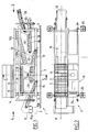
- Figure 1 is a side elevational view of the installation for to implement the invention.
- Figure 2 is a top view of the installation shown in the figure 1.
- Figure 3 is a front view along 3 of Figure 1.
- Figure 4 is a rear view along 4 of the installation of Figure 1 in a raised position.
- FIG. 5 is a transverse view along 5-5 of FIG. 1.
- Installation 1 comprises a platform 2 which is provided with feet support 4 on the site floor 1, in the installation service position 1, the platform 2 which supports all of the components of the installation being in a horizontal arrangement.
- the components of the installation 1 carried by the platform 2 comprise a loading hopper 5 into which the materials are poured minerals such as earth or cuttings, the installation of which ensures the sorting and the treatment.
- a grid 6 which extends over the entire section of the hopper 5, in a horizontal plane, in its operating position and which can be raised by a control device hydraulic allowing the grid 6 to pivot by an angle greater than 90 °, as shown in Figure 3.
- the tilting of the grid beyond the vertical position allows the release and the fall outside of the hopper, oversized blocks that could be trapped between the bars 7 of the grid 6.
- the bars 7 are mounted articulated at one of their ends along one of the longitudinal edges of the grid, so that ability to rotate to a vertical position as shown in the figure 3, to ensure the release and the fall of the blocks stuck in the grid 6.
- the hydraulic tilting means of the grid 6 can be advantageously controlled remotely, by a remote control of the type radio or infrared.
- an extractor 8 consisting of a conveyor comprising horizontal rollers and a conveyor belt driven by pulleys in a longitudinal direction of installation 1, in the direction of arrow 9, so as to send the materials contained in the loading hopper 5 to a first part end of a screening installation 10 extending in the longitudinal direction of installation 1, following the loading hopper 5, towards the front of the installation (right part in figure 1 and in figure 2).
- the longitudinal direction of the installation 1 is shown in the figure 1 by the longitudinal axis 11 common to the loading hopper 5, to the extractor 8 and the screening plant 10.
- the screening installation 10 comprises, from its first end located below and directly above the outlet end of the extractor 8, in the longitudinal direction 11, a first screen section 10a and, at the continuation of the first screen section 10a, a second screen section 10b extending from the second end of the first section 10a to the second end of the screening plant 10 or outlet end of the screening plant.
- the extractor 8 is at variable speed so that its flow can be adapted to the type of materials to be sorted contained in the loading hopper 5.
- variable speed of the extractor 8 can be obtained by hydraulic or mechanical means, for example a belt drive or with rollers, or by electromechanical means with variation of frequency or direct current.
- the first and second screen sections 10a and 10b of the installation screen 10 can be made up of two successive sections of a screen made using a known construction technique, for example two successive sections of a star screen or a disc screen.
- a star screen has a plurality of transverse direction shafts perpendicular to the longitudinal direction of product circulation in the screen placed one after the other in the longitudinal direction on which are mounted rotating parts in the shape of stars comprising elastic branches, the rotating parts carried by two successive trees being offset from each other in the transverse direction of the screening plant.
- Such star screens are offered, for example, by the company German BACKERS MASCHINENBAU, and by the Canadian company ERIN SYSTEMS.
- first section 10a and the second screen section 10b are formed in the form of two successive sections of a sieve stars
- the trees bearing the star rotating parts in the two sections screens of the screening plant are driven separately to different speeds from each other, so as to separate materials crude, successively, a first and a second particle size fraction.
- Variable speed and adjustable drive of the screen shafts at stars can be obtained by hydraulic, mechanical drive or electromechanical with frequency variation or direct current.
- a disc screen has a plurality of parallel shafts between them of transverse direction carrying metal discs, for example of polygonal shape, the corners of which are filled with anti-wear pads, spaced apart from one another in the transverse direction, the trees of the screen of transverse direction carrying the discs being arranged successively in the longitudinal direction of the screen, i.e. in the direction of circulation products to be screened and the discs of two successive trees in the longitudinal direction are offset from each other in the direction cross.
- the particle size sorting of materials passing through the screen can be adjusted by adjusting the disc spacing in the direction cross.
- Such a disc screen is offered, for example, by the German company KRONENBERGER GmbH.
- the discs carried by the trees in each successive section of the installation screens are arranged with a spacing, in the direction transverse, adapted to the particle size fraction which we want to ensure separation in the screen section.
- the discs fixed on successive rotating shafts have a first distance
- the discs fixed on successive rotary shafts have a second spacing distance.
- the fraction of separate material corresponding to a desired particle size fraction is collected below the screen, the material flowing by gravity between the rotating star elements or the screen discs.
- first screen section 10a of the installation screen 10 of the device in the form of a star screen and the second screen 10b in the form of a disc screen or conversely, the first screen 10a in the form of a disc screen and the second screen 10b in the form of a star screen.
- the setting characteristics of the star screen and the screen discs are determined so as to separate the size fractions mineral materials passing through the screen.
- a first conveyor 12 is arranged below the first screen 10a of the screening installation 10, along its entire length and below a part of the extractor 8.
- the first continuous type conveyor 12 extends and ensures a circulation of materials, in the longitudinal direction, so to be able to continuously recover the particle size fraction flowing by gravity below the first screen 10a of the screening plant 10 and transport it in the longitudinal direction towards the rear of the device 1.
- a spill hopper 13 can be placed below the first screen 10a of the screening plant 10, so as to direct the fraction particle size separated by the screen 10a towards the upper surface of the carpet of the first conveyor 12.
- the outlet end part or rear part of the first conveyor 12 is disposed above one end entry of a recovery conveyor 14 ensuring the recovery of materials dumped at the outlet of the first conveyor 12, the mixture of materials and feeding a mixer 15.
- a second conveyor 16 is placed below and directly above the second screen 10b or second section of the installation screening 10, so that the materials corresponding to the second particle size fraction separated from the raw materials from the first screen section 10a through the second screen 10b discharge, preferably via a chute 17, on the upper surface of the second conveyor belt 16 which ensures their continuous recovery.
- the second conveyor 16 has two directions of circulation, in the longitudinal direction 11 of the installation according to the invention, as represented by the double arrow 18 in FIG. 1.
- the fraction of material separated by the screen having a second particle size is poured onto the upper surface of the first conveyor 12, generally produced in the form of a weighing conveyor.
- Materials made up of the first particle size fraction flowing from the first screen 10a on the belt of the first conveyor 12 and by the second particle size fraction of the materials coming from the second screen 10b dumped on the first conveyor by the second conveyor 16 are continuously discharged at the outlet end of the first conveyor 12 on the recovery conveyor 14 which is produced in the form of a conveyor having a mixing feed conveyor which makes it possible to carry out a substantially homogeneous mixture of the two particle size fractions materials before pouring the mixture of materials into the mixer 15.
- the materials of the second particle size fraction separated by the second screen 10b are discharged at the end of exit of the second conveyor 16, for example to be scrapped or to be transferred to a crusher allowing an adjustment to be made and a particle size homogenization of the second fraction of materials separated by the second screen 10b.
- the materials crushed and whose particle size has been homogenized can be reintroduced in the installation, through a transporter to be discharged, for example on the first transporter 12, then transported with the first particle size fraction of the materials to the transporter recovery 14 which ensures their mixing.
- These crushed and homogenized materials as for their particle size can also be poured directly on the recovery conveyor 14.
- the second conveyor 16 can advantageously be produced under the form of a variable speed conveyor whose speed can be controlled to regulate the flow of transported materials.
- the installation 1 further comprises a conveyor 20 for evacuating refusals from the screening installation 10, of which a first end, or entry end, is arranged vertically and below from the outlet end of the screening plant 10, at the end outlet of the second screen section 10b.
- Refusals transported by the evacuation transporter 20 to the end before installation 1 can be removed and disposed of or transferred in a crusher, so that their particle size is adjusted and homogenized. These crushed and homogenized materials can be reintroduced into the installation, via the first conveyor 12, the second transporter 16 or the recovery transporter 14.
- the mixer 15 can be a mixer with arms and paddles with two parallel trees or even a single tree, depending on the flow of materials introduced into the mixer.
- the mixer 15 can also be a disc mixer and articulated arms.
- the type of mixer is suitable for materials introduced for their treatment in the mixer.
- the mixer 15 can be produced to be able to tilt in the transverse direction of the installation, towards the mixer outlet. We can thus adapt the mixer to the characteristics of cohesion of the mixtures produced in the mixer.
- the mixer comprises, below rotary shafts 15a and 15b carrying the mixing of the mixer, a bottom which is preferably movable in the direction vertical, thanks to hydraulic or mechanical holding cylinders, and articulated around a longitudinal steering axis so that it can be tilted so that the release and cleaning of the mixer are carried out, when needed.
- the installation 1 according to the invention comprises means for correcting the particle size or improving the characteristics physical properties of the product to be manufactured.
- the installation 1 may include, as shown in particular in FIG. 5, a metering and additive supply assembly 19 allowing an additive to be introduced into the materials which will then be introduced in the blender.
- Such an additive can be constituted for example by a solid binder such as lime, cement, gypsum or products derived from these binders or again by a stabilizer such as bentonite.
- the assembly 19 allowing the introduction into the materials of additives in metered quantity includes in particular a silo or hopper 21 and a dosing screw 22 making it possible to extract, in metered quantity, the additive contained in the silo 21 and pour it on the first conveyor 12 ensuring the transfer to the mixing conveyor 14 for the recovery of the first and the second particle size fractions of the materials, separated by the installation screening 10.
- the silo or buffer hopper 21 can be supplied by successive loads contained in bags or continuously from a storage silo outside installation 1 according to the invention.
- the assembly 19 for metering and supplying additives to the materials from the screening plant may additionally include a set supply of water in metered quantity comprising in particular a tank 23 on board the installation platform 2 to provide constant water suction conditions over time to allow optimal operation of the installation according to the invention.
- the dosing screw 22 associated with the additive silo 21 which can be of volumetric or weight type is subject to the overall flow of materials transported by the first conveyor 12 made in the form of a weighing conveyor.
- a weighing table associated with the conveyor belt first conveyor 12 provides a flow signal to an installation switch arranged in an electrical cabinet supplying power and control (reference 24 in Figure 2).
- the cabinet 24 on board the installation platform 2 contains a supply control and servo unit additive, such as screw 22 for supplying solid binder or means for supply of liquid such as water from tank 23 or other means supply of various additives which are added to the materials, quantities dosed according to the signal provided by the weighing table of the first transporter 12 or weigher transporter.
- a supply control and servo unit additive such as screw 22 for supplying solid binder or means for supply of liquid such as water from tank 23 or other means supply of various additives which are added to the materials, quantities dosed according to the signal provided by the weighing table of the first transporter 12 or weigher transporter.
- the cabinet 24 contains all the power circuits and the installation control and servo means 1.
- cable remote control means by infrared or radio wave can be associated with the installation to ensure remote control of the installation, for example for commissioning or stopping it.
- the installation may include a set preparation and dosage of a bituminous emulsion which can be by example introduced into the mixer 15 to obtain, at the outlet of the mixer 15, a product such as bass mixed with bituminous emulsion or cold mixes.
- a bituminous emulsion which can be by example introduced into the mixer 15 to obtain, at the outlet of the mixer 15, a product such as bass mixed with bituminous emulsion or cold mixes.
- bituminous emulsion preparation and dosage set can be combined with a bitumen foam production unit for manufacture a product consisting of gravel mixed with bitumen foam.
- the chassis 2 which may include, as shown in Figures 1, 2 and 4, crutches 25, for example four vertical extendable stands which can be fixed on supports transversely extending the installation, relative to the edges transverse of the platform or chassis 2, at the front and at the rear.
- the set of crutches constitutes a widening and lifting system of the platform and the whole installation, as shown in FIG. 4 which shows the crutches 25 in their deployed position ensuring the lifting of the platform 2 and of the installation 1 as a whole. In this raised position, the platform of a road trailer can be engaged under chassis 2 for loading and transferring the installation 1.
- the platform 2 can be equipped with a running gear and a fifth wheel coupling, so as to constitute in itself a road semi-trailer.
- Platform 2 can also be equipped with tracks allowing to move it on a site regardless of the nature of the site soil.
- the platform can be equipped with a shield allowing the support of a loading ramp, for example a ramp loading hopper 5 loading raw materials and / or additive storage silo 21.
- the device according to the invention makes it possible to carry out sorting and processing of very diverse materials, in particular to obtain mixtures or products containing at least two particle size fractions different extracts from a raw starting product.
- the installation according to the invention allows sorting and classification raw materials prerequisites if this sorting and classification is required. If sorting and classification is not necessary, it is possible to eliminate the passage through the screening plant 10, for example by providing for assembly of the screening installation 10 on the platform 2 allowing its displacement in the longitudinal direction, so that the raw products extracted from the loading hopper 5 are no longer spilled on the inlet end of the screen, but directly on the first carrier 12.
- the mixer 15 can be made of separable from the recovery conveyor 14 and associated with means lifting to place it in a raised position in which materials spilled by the recovery transporter no longer enter the mixer but are dumped directly to the outside and back of installation 1.
- the installation according to the invention can also make it possible to carry out products from mixtures of materials with more than two particle size fractions. It is possible to provide a screen comprising, one at the following the other, more than two screening sections, more than two fractions of different particle sizes and, below each of the sections of the successive screening plant, a transporter similar to the second carrier 16, two-way traffic, successive carriers being placed so that their respective outlet and inlet portions are superimposed, so as to recover the materials according to the different grain sizes on a single transporter which can be a transporter weigher similar to the first conveyor 12.
- the installation according to the invention therefore makes it possible to carry out numerous sorting and classification of mineral materials and many processing operations for these materials, in particular products containing at least two particle size fractions.
Landscapes
- Engineering & Computer Science (AREA)
- Architecture (AREA)
- Civil Engineering (AREA)
- Structural Engineering (AREA)
- Processing Of Solid Wastes (AREA)
Abstract
Description
Claims (16)
- Dispositif de traitement de matériaux minéraux tels que des terres ou des matériaux de récupération, comportant une trémie de réception (5) des matériaux minéraux, un extracteur (8) de matériaux minéraux contenus dans la trémie (5), par le dessous de la trémie (5), au moins un crible (10) alimenté en matériaux minéraux par l'extracteur (8) et au moins un premier transporteur (12) de matériaux minéraux séparés par le crible, disposé en-dessous d'une partie au moins du crible (10), dans une direction longitudinale (11) du dispositif de traitement (1), caractérisé par le fait que le crible (10) comporte un premier tronçon (10a) de séparation d'une première fraction granulométrique des matériaux minéraux disposé au-dessus du premier transporteur (12) et au moins un second tronçon (10b) de séparation d'une seconde fraction granulométrique des matériaux minéraux disposé à la suite du premier tronçon (10a), dans la direction longitudinale (11) du dispositif, et qu'au moins un second transporteur (16) comportant une extrémité placée au-dessus du premier transporteur (12) est disposé en-dessous du second tronçon (10b) du crible (10) dans la direction longitudinale (11).
- Dispositif suivant la revendication 1, caractérisé par le fait que le second transporteur (16) est un transporteur comportant des moyens de commande de déplacement dans l'un quelconque de deux sens de déplacement opposés (18), dans la direction longitudinale (11) du dispositif de traitement (1).
- Dispositif suivant l'une quelconque des revendications 1 et 2, caractérisé par le fait que le premier transporteur (12) est un transporteur peseur comportant une table de pesage pour la mesure d'un débit de matériaux transportés par le premier transporteur (12).
- Dispositif suivant l'une quelconque des revendications 1 à 3, caractérisé par le fait que le crible (10) est un crible à étoiles et comporte un premier tronçon (10a) et au moins un second tronçon (10b) dans lesquels des arbres de direction transversale portant des éléments rotatifs en forme d'étoile sont entraínés à des vitesses différentes, de manière à réaliser la séparation de la première fraction granulométrique des matériaux minéraux à travers le premier tronçon (10a) du crible (10) et la séparation de la seconde fraction granulométrique des matériaux minéraux à travers le second tronçon (10b) du crible (10).
- Dispositif suivant l'une quelconque des revendications 1 à 3, caractérisé par le fait que le crible (10) est un crible à disques comportant des arbres transversaux rotatifs successifs portant des disques de séparation, écartés l'un de l'autre dans la direction transversale sur chacun des arbres, les disques fixés sur les arbres rotatifs du premier tronçon (10a) du crible (10) ayant une première distance d'écartement et les disques fixés sur les arbres rotatifs successifs du second tronçon (10b) du crible (10) ayant une seconde distance d'écartement, de manière à permettre le passage, à travers le premier tronçon de crible (10a), de la première fraction granulométrique des matériaux minéraux et, à travers le second tronçon (10b) du crible (10) de la seconde fraction granulométrique des matériaux minéraux.
- Dispositif suivant l'une quelconque des revendications 1 à 3, caractérisé par le fait que le crible (10) comporte un premier tronçon (10a) constitué par l'un d'un crible à étoiles et d'un crible à disques, et un second tronçon (10b) constitué par l'un d'un crible à disques et d'un crible à étoiles, le premier tronçon (10a) du crible (10) et le second tronçon (10b) du crible (10) étant de types différents, de manière à permettre le passage, à travers le premier tronçon (10a) du crible (10), de la première fraction granulométrique des matériaux minéraux et, à travers le second tronçon (10b) du crible (10), de la seconde fraction granulométrique des matériaux minéraux.
- Dispositif suivant l'une quelconque des revendications 1 à 6, caractérisé par le fait qu'il comporte de plus, à l'une des extrémités longitudinales ou extrémité arrière du dispositif (1), un mélangeur (15) et un transporteur de reprise mélangeur (14) ayant une extrémité d'entrée à l'aplomb et en-dessous d'une extrémité de sortie du premier transporteur (12) et une seconde extrémité opposée dans la direction longitudinale (11) ou extrémité de sortie placée de manière à déverser les matériaux minéraux dans le mélangeur (15).
- Dispositif suivant l'une quelconque des revendications 1 à 7, caractérisé par le fait qu'il comporte de plus un ensemble (19) de fourniture et de dosage d'additifs constitués par l'un au moins d'un liant solide ou liquide, de l'eau, du bitume, d'une émulsion de bitume, et d'un adjuvant.
- Dispositif suivant la revendication 8, caractérisé par le fait que l'ensemble de dosage et de fourniture d'additif (19) comporte un silo (21) et une vis d'extraction et de dosage (22) pour extraire du silo (21) un additif en quantité dosée et l'incorporer aux matériaux minéraux séparés par le crible (10) et transportés par le premier transporteur (12).
- Dispositif selon la revendication 9, caractérisé par le fait que l'installation comporte des moyens de commande (24) d'un débit volumétrique ou pondéral d'additifs par la vis (22).
- Dispositif suivant la revendication 10, caractérisé par le fait que le débit d'additif de la vis doseuse (22) est asservi à une mesure de débit pondéral des matériaux minéraux séparés par le crible (10) sur le premier transporteur (12) réalisé sous la forme d'un transporteur comportant une table de pesée.
- Dispositif suivant l'une quelconque des revendications 1 à 11, caractérisé par le fait que le dispositif de traitement est porté par une plate-forme (2) ayant une disposition sensiblement horizontale en service sur le sol (3) d'un chantier.
- Dispositif suivant la revendication 12, caractérisé par le fait que la plate-forme (2) porte l'un au moins des moyens de support sur le sol (3) du chantier suivant :béquille (25) réglable en hauteur,chenille,train roulant.
- Dispositif suivant la revendication 12, caractérisé par le fait que la plate-forme (2) comporte au moins un train roulant et une sellette d'attelage, de manière à constituer une semi-remorque routière.
- Procédé de traitement de matériaux bruts tels que des terres ou des matériaux de récupération consistant à faire passer les matériaux bruts dans une installation de criblage (10) et à récupérer au moins une fraction granulométrique des matériaux bruts, caractérisé par le fait qu'on fait passer successivement les matériaux bruts à travers un premier tronçon de crible (10a) pour séparer des matériaux bruts, une première fraction granulométrique, puis à travers au moins un second tronçon de crible (10b) pour séparer des matériaux bruts au moins une seconde fraction granulométrique, et qu'on récupère la première fraction granulométrique et la seconde fraction granulométrique des matériaux, respectivement en-dessous du premier tronçon (10a) et du second tronçon de crible (10b), successivement dans une direction (11) de circulation des matériaux.
- Procédé suivant la revendication 15, caractérisé par le fait qu'on incorpore en continu l'au moins une seconde fraction granulométrique à la première fraction granulométrique des matériaux.
Applications Claiming Priority (2)
| Application Number | Priority Date | Filing Date | Title |
|---|---|---|---|
| FR0115874 | 2001-12-07 | ||
| FR0115874A FR2833194B1 (fr) | 2001-12-07 | 2001-12-07 | Dispositif et procede de traitement de materiaux mineraux tels que des terres ou des materiaux de recuperation |
Publications (2)
| Publication Number | Publication Date |
|---|---|
| EP1317969A1 true EP1317969A1 (fr) | 2003-06-11 |
| EP1317969B1 EP1317969B1 (fr) | 2006-03-08 |
Family
ID=8870245
Family Applications (1)
| Application Number | Title | Priority Date | Filing Date |
|---|---|---|---|
| EP20020292984 Expired - Lifetime EP1317969B1 (fr) | 2001-12-07 | 2002-12-03 | Dispositif et procédé de traitement de matériaux mineraux tels que des terres ou des matériaux de recuperation |
Country Status (3)
| Country | Link |
|---|---|
| EP (1) | EP1317969B1 (fr) |
| DE (1) | DE60209679D1 (fr) |
| FR (1) | FR2833194B1 (fr) |
Cited By (4)
| Publication number | Priority date | Publication date | Assignee | Title |
|---|---|---|---|---|
| EP1698732A1 (fr) * | 2005-03-02 | 2006-09-06 | Dellschau Solid Baumaschinen Gmbh | Dispositif mobile compact de traitement de sols |
| FR2899835A1 (fr) * | 2006-04-12 | 2007-10-19 | Concept Travaux Publics Sarl | Installation transportable modulaire pour la valorisation des dechets de travaux publics |
| FR2899915A1 (fr) * | 2006-04-14 | 2007-10-19 | Famatec Soc Par Actions Simpli | Procede et ensemble de traitement de materiaux mineraux provenant d'une tranchee |
| EP2362025A1 (fr) * | 2010-02-26 | 2011-08-31 | Yorkshire Water Services Limited | Appareil de recyclage de matériaux |
Families Citing this family (1)
| Publication number | Priority date | Publication date | Assignee | Title |
|---|---|---|---|---|
| FR2889096B1 (fr) | 2005-07-29 | 2007-11-02 | Recymo Sarl | Installation de traitement de deblais limoneux d'un chantier et procede de traitement de ces deblais limoneux mettant en oeuvre ladite installation |
Citations (6)
| Publication number | Priority date | Publication date | Assignee | Title |
|---|---|---|---|---|
| DE4017652A1 (de) * | 1990-06-01 | 1991-12-05 | Gaz Industrieanlagen Gmbh | Vorrichtung zum sieben von haus- und/oder industriemuell |
| DE4309671C1 (de) * | 1993-03-25 | 1994-05-05 | Gaz Industrieanlagen Gmbh | Vorrichtung zur Aufbereitung von Baustoffabfällen |
| DE4408903A1 (de) * | 1994-03-16 | 1995-09-21 | Ernst Josef Kronenberger | Sieb zur Aufbereitung bindiger Aushubmassen für den Wiedereinbau |
| FR2756769A1 (fr) * | 1996-12-11 | 1998-06-12 | Eds Equipements De Depollution | Machine mobile pour traiter les terres naturelles des sols pour pouvoir les reutiliser en remblais et pour depolluer les sols pollues |
| DE29810885U1 (de) * | 1998-06-18 | 1998-08-20 | Neuenhauser Maschinenbau Gmbh & Co. Kg, 49828 Neuenhaus | Siebanlage |
| US5975441A (en) * | 1997-12-29 | 1999-11-02 | Burkholder; Melvin M. | Apparatus for separating rocks from soil |
-
2001
- 2001-12-07 FR FR0115874A patent/FR2833194B1/fr not_active Expired - Fee Related
-
2002
- 2002-12-03 EP EP20020292984 patent/EP1317969B1/fr not_active Expired - Lifetime
- 2002-12-03 DE DE60209679T patent/DE60209679D1/de not_active Expired - Lifetime
Patent Citations (6)
| Publication number | Priority date | Publication date | Assignee | Title |
|---|---|---|---|---|
| DE4017652A1 (de) * | 1990-06-01 | 1991-12-05 | Gaz Industrieanlagen Gmbh | Vorrichtung zum sieben von haus- und/oder industriemuell |
| DE4309671C1 (de) * | 1993-03-25 | 1994-05-05 | Gaz Industrieanlagen Gmbh | Vorrichtung zur Aufbereitung von Baustoffabfällen |
| DE4408903A1 (de) * | 1994-03-16 | 1995-09-21 | Ernst Josef Kronenberger | Sieb zur Aufbereitung bindiger Aushubmassen für den Wiedereinbau |
| FR2756769A1 (fr) * | 1996-12-11 | 1998-06-12 | Eds Equipements De Depollution | Machine mobile pour traiter les terres naturelles des sols pour pouvoir les reutiliser en remblais et pour depolluer les sols pollues |
| US5975441A (en) * | 1997-12-29 | 1999-11-02 | Burkholder; Melvin M. | Apparatus for separating rocks from soil |
| DE29810885U1 (de) * | 1998-06-18 | 1998-08-20 | Neuenhauser Maschinenbau Gmbh & Co. Kg, 49828 Neuenhaus | Siebanlage |
Cited By (4)
| Publication number | Priority date | Publication date | Assignee | Title |
|---|---|---|---|---|
| EP1698732A1 (fr) * | 2005-03-02 | 2006-09-06 | Dellschau Solid Baumaschinen Gmbh | Dispositif mobile compact de traitement de sols |
| FR2899835A1 (fr) * | 2006-04-12 | 2007-10-19 | Concept Travaux Publics Sarl | Installation transportable modulaire pour la valorisation des dechets de travaux publics |
| FR2899915A1 (fr) * | 2006-04-14 | 2007-10-19 | Famatec Soc Par Actions Simpli | Procede et ensemble de traitement de materiaux mineraux provenant d'une tranchee |
| EP2362025A1 (fr) * | 2010-02-26 | 2011-08-31 | Yorkshire Water Services Limited | Appareil de recyclage de matériaux |
Also Published As
| Publication number | Publication date |
|---|---|
| DE60209679D1 (de) | 2006-05-04 |
| EP1317969B1 (fr) | 2006-03-08 |
| FR2833194B1 (fr) | 2004-09-24 |
| FR2833194A1 (fr) | 2003-06-13 |
Similar Documents
| Publication | Publication Date | Title |
|---|---|---|
| US4861461A (en) | Pipeline padding machine and method | |
| AU2018202149B2 (en) | A Transfer Conveyor Assembly For a Screening Apparatus | |
| US10683178B2 (en) | Systems and methods for processing earthen slurries | |
| EP1328355B1 (fr) | Unite mobile de criblage | |
| US20200223346A1 (en) | Improved wet plant for a sand mine | |
| US5335784A (en) | Dump platform materials screener | |
| CA2105232C (fr) | Crible; methode pour la separation de plusieurs materiaux melanges | |
| EP4267317B1 (fr) | Trémie de tamisage | |
| US6065606A (en) | Elevatable frame for transportable sorting machines | |
| US11913317B2 (en) | Proppants processing system and method | |
| EP2346617B1 (fr) | Dispositif et procede pour la recuperation de materiaux | |
| EP1317969B1 (fr) | Dispositif et procédé de traitement de matériaux mineraux tels que des terres ou des matériaux de recuperation | |
| FR2646186A1 (fr) | Machine de traitement en place de materiaux, tels que des limons et des craies pour la construction d'une couche de fondation de chaussee notamment de chaussee d'autoroute | |
| US9937637B1 (en) | Mobile mixing apparatus with adjustable mixing paddles | |
| US1611026A (en) | Crushing and screening apparatus | |
| FR2568487A1 (fr) | Installation transportable pour traiter des gravois de construction | |
| CN114515699B (zh) | 一种金桔筛选装置 | |
| FR2756769A1 (fr) | Machine mobile pour traiter les terres naturelles des sols pour pouvoir les reutiliser en remblais et pour depolluer les sols pollues | |
| JP3375588B2 (ja) | 自走式土質改良機械 | |
| JPH0711144Y2 (ja) | コンクリート、舗装用合材用砂の製造装置 | |
| FR2536771A1 (fr) | Installation pour l'alimentation volumetrique ou ponderale de materiaux, le dosage de produits pulverulents, de liants hydrauliques ou hydrocarbones, et leur malaxage pour realiser un melange destine a etre utilise pour l'amelioration et/ou la stabilisation des sols en travaux de terrassements, routes, aerodromes et barrages masses | |
| FR2815650A1 (fr) | Machine pour le traitement de terres et de materiaux analogues | |
| BE1014610A3 (nl) | Werkwijze voor het mengen van vaste materie en menger voor het toepassen van deze werkwijze. | |
| CN217249554U (zh) | 工程施工用土方破碎装置 | |
| FR2899915A1 (fr) | Procede et ensemble de traitement de materiaux mineraux provenant d'une tranchee |
Legal Events
| Date | Code | Title | Description |
|---|---|---|---|
| PUAI | Public reference made under article 153(3) epc to a published international application that has entered the european phase |
Free format text: ORIGINAL CODE: 0009012 |
|
| AK | Designated contracting states |
Designated state(s): AT BE BG CH CY CZ DE DK EE ES FI FR GB GR IE IT LI LU MC NL PT SE SI SK TR |
|
| AX | Request for extension of the european patent |
Extension state: AL LT LV MK RO |
|
| 17P | Request for examination filed |
Effective date: 20031205 |
|
| AKX | Designation fees paid |
Designated state(s): CZ DE ES FR GB IT |
|
| 17Q | First examination report despatched |
Effective date: 20040902 |
|
| GRAP | Despatch of communication of intention to grant a patent |
Free format text: ORIGINAL CODE: EPIDOSNIGR1 |
|
| GRAS | Grant fee paid |
Free format text: ORIGINAL CODE: EPIDOSNIGR3 |
|
| GRAA | (expected) grant |
Free format text: ORIGINAL CODE: 0009210 |
|
| AK | Designated contracting states |
Kind code of ref document: B1 Designated state(s): CZ DE ES FR GB IT |
|
| PG25 | Lapsed in a contracting state [announced via postgrant information from national office to epo] |
Ref country code: IT Free format text: LAPSE BECAUSE OF FAILURE TO SUBMIT A TRANSLATION OF THE DESCRIPTION OR TO PAY THE FEE WITHIN THE PRESCRIBED TIME-LIMIT;WARNING: LAPSES OF ITALIAN PATENTS WITH EFFECTIVE DATE BEFORE 2007 MAY HAVE OCCURRED AT ANY TIME BEFORE 2007. THE CORRECT EFFECTIVE DATE MAY BE DIFFERENT FROM THE ONE RECORDED. Effective date: 20060308 Ref country code: GB Free format text: LAPSE BECAUSE OF FAILURE TO SUBMIT A TRANSLATION OF THE DESCRIPTION OR TO PAY THE FEE WITHIN THE PRESCRIBED TIME-LIMIT Effective date: 20060308 |
|
| REG | Reference to a national code |
Ref country code: GB Ref legal event code: FG4D Free format text: NOT ENGLISH |
|
| REF | Corresponds to: |
Ref document number: 60209679 Country of ref document: DE Date of ref document: 20060504 Kind code of ref document: P |
|
| PG25 | Lapsed in a contracting state [announced via postgrant information from national office to epo] |
Ref country code: DE Free format text: LAPSE BECAUSE OF FAILURE TO SUBMIT A TRANSLATION OF THE DESCRIPTION OR TO PAY THE FEE WITHIN THE PRESCRIBED TIME-LIMIT Effective date: 20060609 |
|
| PG25 | Lapsed in a contracting state [announced via postgrant information from national office to epo] |
Ref country code: ES Free format text: LAPSE BECAUSE OF FAILURE TO SUBMIT A TRANSLATION OF THE DESCRIPTION OR TO PAY THE FEE WITHIN THE PRESCRIBED TIME-LIMIT Effective date: 20060619 |
|
| GBV | Gb: ep patent (uk) treated as always having been void in accordance with gb section 77(7)/1977 [no translation filed] |
Effective date: 20060308 |
|
| PLBE | No opposition filed within time limit |
Free format text: ORIGINAL CODE: 0009261 |
|
| STAA | Information on the status of an ep patent application or granted ep patent |
Free format text: STATUS: NO OPPOSITION FILED WITHIN TIME LIMIT |
|
| 26N | No opposition filed |
Effective date: 20061211 |
|
| PG25 | Lapsed in a contracting state [announced via postgrant information from national office to epo] |
Ref country code: CZ Free format text: LAPSE BECAUSE OF FAILURE TO SUBMIT A TRANSLATION OF THE DESCRIPTION OR TO PAY THE FEE WITHIN THE PRESCRIBED TIME-LIMIT Effective date: 20060308 |
|
| PGFP | Annual fee paid to national office [announced via postgrant information from national office to epo] |
Ref country code: FR Payment date: 20131212 Year of fee payment: 12 |
|
| REG | Reference to a national code |
Ref country code: FR Ref legal event code: ST Effective date: 20150831 |
|
| PG25 | Lapsed in a contracting state [announced via postgrant information from national office to epo] |
Ref country code: FR Free format text: LAPSE BECAUSE OF NON-PAYMENT OF DUE FEES Effective date: 20141231 |