EP1317050A2 - Hybrid farm tractor power train - Google Patents
Hybrid farm tractor power train Download PDFInfo
- Publication number
- EP1317050A2 EP1317050A2 EP02079634A EP02079634A EP1317050A2 EP 1317050 A2 EP1317050 A2 EP 1317050A2 EP 02079634 A EP02079634 A EP 02079634A EP 02079634 A EP02079634 A EP 02079634A EP 1317050 A2 EP1317050 A2 EP 1317050A2
- Authority
- EP
- European Patent Office
- Prior art keywords
- power train
- power
- electric machines
- shaft
- electric
- Prior art date
- Legal status (The legal status is an assumption and is not a legal conclusion. Google has not performed a legal analysis and makes no representation as to the accuracy of the status listed.)
- Granted
Links
Images
Classifications
-
- B—PERFORMING OPERATIONS; TRANSPORTING
- B60—VEHICLES IN GENERAL
- B60K—ARRANGEMENT OR MOUNTING OF PROPULSION UNITS OR OF TRANSMISSIONS IN VEHICLES; ARRANGEMENT OR MOUNTING OF PLURAL DIVERSE PRIME-MOVERS IN VEHICLES; AUXILIARY DRIVES FOR VEHICLES; INSTRUMENTATION OR DASHBOARDS FOR VEHICLES; ARRANGEMENTS IN CONNECTION WITH COOLING, AIR INTAKE, GAS EXHAUST OR FUEL SUPPLY OF PROPULSION UNITS IN VEHICLES
- B60K6/00—Arrangement or mounting of plural diverse prime-movers for mutual or common propulsion, e.g. hybrid propulsion systems comprising electric motors and internal combustion engines ; Control systems therefor, i.e. systems controlling two or more prime movers, or controlling one of these prime movers and any of the transmission, drive or drive units Informative references: mechanical gearings with secondary electric drive F16H3/72; arrangements for handling mechanical energy structurally associated with the dynamo-electric machine H02K7/00; machines comprising structurally interrelated motor and generator parts H02K51/00; dynamo-electric machines not otherwise provided for in H02K see H02K99/00
- B60K6/20—Arrangement or mounting of plural diverse prime-movers for mutual or common propulsion, e.g. hybrid propulsion systems comprising electric motors and internal combustion engines ; Control systems therefor, i.e. systems controlling two or more prime movers, or controlling one of these prime movers and any of the transmission, drive or drive units Informative references: mechanical gearings with secondary electric drive F16H3/72; arrangements for handling mechanical energy structurally associated with the dynamo-electric machine H02K7/00; machines comprising structurally interrelated motor and generator parts H02K51/00; dynamo-electric machines not otherwise provided for in H02K see H02K99/00 the prime-movers consisting of electric motors and internal combustion engines, e.g. HEVs
- B60K6/22—Arrangement or mounting of plural diverse prime-movers for mutual or common propulsion, e.g. hybrid propulsion systems comprising electric motors and internal combustion engines ; Control systems therefor, i.e. systems controlling two or more prime movers, or controlling one of these prime movers and any of the transmission, drive or drive units Informative references: mechanical gearings with secondary electric drive F16H3/72; arrangements for handling mechanical energy structurally associated with the dynamo-electric machine H02K7/00; machines comprising structurally interrelated motor and generator parts H02K51/00; dynamo-electric machines not otherwise provided for in H02K see H02K99/00 the prime-movers consisting of electric motors and internal combustion engines, e.g. HEVs characterised by apparatus, components or means specially adapted for HEVs
- B60K6/36—Arrangement or mounting of plural diverse prime-movers for mutual or common propulsion, e.g. hybrid propulsion systems comprising electric motors and internal combustion engines ; Control systems therefor, i.e. systems controlling two or more prime movers, or controlling one of these prime movers and any of the transmission, drive or drive units Informative references: mechanical gearings with secondary electric drive F16H3/72; arrangements for handling mechanical energy structurally associated with the dynamo-electric machine H02K7/00; machines comprising structurally interrelated motor and generator parts H02K51/00; dynamo-electric machines not otherwise provided for in H02K see H02K99/00 the prime-movers consisting of electric motors and internal combustion engines, e.g. HEVs characterised by apparatus, components or means specially adapted for HEVs characterised by the transmission gearings
- B60K6/365—Arrangement or mounting of plural diverse prime-movers for mutual or common propulsion, e.g. hybrid propulsion systems comprising electric motors and internal combustion engines ; Control systems therefor, i.e. systems controlling two or more prime movers, or controlling one of these prime movers and any of the transmission, drive or drive units Informative references: mechanical gearings with secondary electric drive F16H3/72; arrangements for handling mechanical energy structurally associated with the dynamo-electric machine H02K7/00; machines comprising structurally interrelated motor and generator parts H02K51/00; dynamo-electric machines not otherwise provided for in H02K see H02K99/00 the prime-movers consisting of electric motors and internal combustion engines, e.g. HEVs characterised by apparatus, components or means specially adapted for HEVs characterised by the transmission gearings with the gears having orbital motion
-
- A—HUMAN NECESSITIES
- A01—AGRICULTURE; FORESTRY; ANIMAL HUSBANDRY; HUNTING; TRAPPING; FISHING
- A01D—HARVESTING; MOWING
- A01D69/00—Driving mechanisms or parts thereof for harvesters or mowers
- A01D69/02—Driving mechanisms or parts thereof for harvesters or mowers electric
- A01D69/025—Electric hybrid systems
-
- B—PERFORMING OPERATIONS; TRANSPORTING
- B60—VEHICLES IN GENERAL
- B60K—ARRANGEMENT OR MOUNTING OF PROPULSION UNITS OR OF TRANSMISSIONS IN VEHICLES; ARRANGEMENT OR MOUNTING OF PLURAL DIVERSE PRIME-MOVERS IN VEHICLES; AUXILIARY DRIVES FOR VEHICLES; INSTRUMENTATION OR DASHBOARDS FOR VEHICLES; ARRANGEMENTS IN CONNECTION WITH COOLING, AIR INTAKE, GAS EXHAUST OR FUEL SUPPLY OF PROPULSION UNITS IN VEHICLES
- B60K6/00—Arrangement or mounting of plural diverse prime-movers for mutual or common propulsion, e.g. hybrid propulsion systems comprising electric motors and internal combustion engines ; Control systems therefor, i.e. systems controlling two or more prime movers, or controlling one of these prime movers and any of the transmission, drive or drive units Informative references: mechanical gearings with secondary electric drive F16H3/72; arrangements for handling mechanical energy structurally associated with the dynamo-electric machine H02K7/00; machines comprising structurally interrelated motor and generator parts H02K51/00; dynamo-electric machines not otherwise provided for in H02K see H02K99/00
- B60K6/20—Arrangement or mounting of plural diverse prime-movers for mutual or common propulsion, e.g. hybrid propulsion systems comprising electric motors and internal combustion engines ; Control systems therefor, i.e. systems controlling two or more prime movers, or controlling one of these prime movers and any of the transmission, drive or drive units Informative references: mechanical gearings with secondary electric drive F16H3/72; arrangements for handling mechanical energy structurally associated with the dynamo-electric machine H02K7/00; machines comprising structurally interrelated motor and generator parts H02K51/00; dynamo-electric machines not otherwise provided for in H02K see H02K99/00 the prime-movers consisting of electric motors and internal combustion engines, e.g. HEVs
- B60K6/22—Arrangement or mounting of plural diverse prime-movers for mutual or common propulsion, e.g. hybrid propulsion systems comprising electric motors and internal combustion engines ; Control systems therefor, i.e. systems controlling two or more prime movers, or controlling one of these prime movers and any of the transmission, drive or drive units Informative references: mechanical gearings with secondary electric drive F16H3/72; arrangements for handling mechanical energy structurally associated with the dynamo-electric machine H02K7/00; machines comprising structurally interrelated motor and generator parts H02K51/00; dynamo-electric machines not otherwise provided for in H02K see H02K99/00 the prime-movers consisting of electric motors and internal combustion engines, e.g. HEVs characterised by apparatus, components or means specially adapted for HEVs
- B60K6/38—Arrangement or mounting of plural diverse prime-movers for mutual or common propulsion, e.g. hybrid propulsion systems comprising electric motors and internal combustion engines ; Control systems therefor, i.e. systems controlling two or more prime movers, or controlling one of these prime movers and any of the transmission, drive or drive units Informative references: mechanical gearings with secondary electric drive F16H3/72; arrangements for handling mechanical energy structurally associated with the dynamo-electric machine H02K7/00; machines comprising structurally interrelated motor and generator parts H02K51/00; dynamo-electric machines not otherwise provided for in H02K see H02K99/00 the prime-movers consisting of electric motors and internal combustion engines, e.g. HEVs characterised by apparatus, components or means specially adapted for HEVs characterised by the driveline clutches
- B60K6/387—Actuated clutches, i.e. clutches engaged or disengaged by electric, hydraulic or mechanical actuating means
-
- B—PERFORMING OPERATIONS; TRANSPORTING
- B60—VEHICLES IN GENERAL
- B60K—ARRANGEMENT OR MOUNTING OF PROPULSION UNITS OR OF TRANSMISSIONS IN VEHICLES; ARRANGEMENT OR MOUNTING OF PLURAL DIVERSE PRIME-MOVERS IN VEHICLES; AUXILIARY DRIVES FOR VEHICLES; INSTRUMENTATION OR DASHBOARDS FOR VEHICLES; ARRANGEMENTS IN CONNECTION WITH COOLING, AIR INTAKE, GAS EXHAUST OR FUEL SUPPLY OF PROPULSION UNITS IN VEHICLES
- B60K6/00—Arrangement or mounting of plural diverse prime-movers for mutual or common propulsion, e.g. hybrid propulsion systems comprising electric motors and internal combustion engines ; Control systems therefor, i.e. systems controlling two or more prime movers, or controlling one of these prime movers and any of the transmission, drive or drive units Informative references: mechanical gearings with secondary electric drive F16H3/72; arrangements for handling mechanical energy structurally associated with the dynamo-electric machine H02K7/00; machines comprising structurally interrelated motor and generator parts H02K51/00; dynamo-electric machines not otherwise provided for in H02K see H02K99/00
- B60K6/20—Arrangement or mounting of plural diverse prime-movers for mutual or common propulsion, e.g. hybrid propulsion systems comprising electric motors and internal combustion engines ; Control systems therefor, i.e. systems controlling two or more prime movers, or controlling one of these prime movers and any of the transmission, drive or drive units Informative references: mechanical gearings with secondary electric drive F16H3/72; arrangements for handling mechanical energy structurally associated with the dynamo-electric machine H02K7/00; machines comprising structurally interrelated motor and generator parts H02K51/00; dynamo-electric machines not otherwise provided for in H02K see H02K99/00 the prime-movers consisting of electric motors and internal combustion engines, e.g. HEVs
- B60K6/22—Arrangement or mounting of plural diverse prime-movers for mutual or common propulsion, e.g. hybrid propulsion systems comprising electric motors and internal combustion engines ; Control systems therefor, i.e. systems controlling two or more prime movers, or controlling one of these prime movers and any of the transmission, drive or drive units Informative references: mechanical gearings with secondary electric drive F16H3/72; arrangements for handling mechanical energy structurally associated with the dynamo-electric machine H02K7/00; machines comprising structurally interrelated motor and generator parts H02K51/00; dynamo-electric machines not otherwise provided for in H02K see H02K99/00 the prime-movers consisting of electric motors and internal combustion engines, e.g. HEVs characterised by apparatus, components or means specially adapted for HEVs
- B60K6/40—Arrangement or mounting of plural diverse prime-movers for mutual or common propulsion, e.g. hybrid propulsion systems comprising electric motors and internal combustion engines ; Control systems therefor, i.e. systems controlling two or more prime movers, or controlling one of these prime movers and any of the transmission, drive or drive units Informative references: mechanical gearings with secondary electric drive F16H3/72; arrangements for handling mechanical energy structurally associated with the dynamo-electric machine H02K7/00; machines comprising structurally interrelated motor and generator parts H02K51/00; dynamo-electric machines not otherwise provided for in H02K see H02K99/00 the prime-movers consisting of electric motors and internal combustion engines, e.g. HEVs characterised by apparatus, components or means specially adapted for HEVs characterised by the assembly or relative disposition of components
- B60K6/405—Housings
-
- B—PERFORMING OPERATIONS; TRANSPORTING
- B60—VEHICLES IN GENERAL
- B60K—ARRANGEMENT OR MOUNTING OF PROPULSION UNITS OR OF TRANSMISSIONS IN VEHICLES; ARRANGEMENT OR MOUNTING OF PLURAL DIVERSE PRIME-MOVERS IN VEHICLES; AUXILIARY DRIVES FOR VEHICLES; INSTRUMENTATION OR DASHBOARDS FOR VEHICLES; ARRANGEMENTS IN CONNECTION WITH COOLING, AIR INTAKE, GAS EXHAUST OR FUEL SUPPLY OF PROPULSION UNITS IN VEHICLES
- B60K6/00—Arrangement or mounting of plural diverse prime-movers for mutual or common propulsion, e.g. hybrid propulsion systems comprising electric motors and internal combustion engines ; Control systems therefor, i.e. systems controlling two or more prime movers, or controlling one of these prime movers and any of the transmission, drive or drive units Informative references: mechanical gearings with secondary electric drive F16H3/72; arrangements for handling mechanical energy structurally associated with the dynamo-electric machine H02K7/00; machines comprising structurally interrelated motor and generator parts H02K51/00; dynamo-electric machines not otherwise provided for in H02K see H02K99/00
- B60K6/20—Arrangement or mounting of plural diverse prime-movers for mutual or common propulsion, e.g. hybrid propulsion systems comprising electric motors and internal combustion engines ; Control systems therefor, i.e. systems controlling two or more prime movers, or controlling one of these prime movers and any of the transmission, drive or drive units Informative references: mechanical gearings with secondary electric drive F16H3/72; arrangements for handling mechanical energy structurally associated with the dynamo-electric machine H02K7/00; machines comprising structurally interrelated motor and generator parts H02K51/00; dynamo-electric machines not otherwise provided for in H02K see H02K99/00 the prime-movers consisting of electric motors and internal combustion engines, e.g. HEVs
- B60K6/42—Arrangement or mounting of plural diverse prime-movers for mutual or common propulsion, e.g. hybrid propulsion systems comprising electric motors and internal combustion engines ; Control systems therefor, i.e. systems controlling two or more prime movers, or controlling one of these prime movers and any of the transmission, drive or drive units Informative references: mechanical gearings with secondary electric drive F16H3/72; arrangements for handling mechanical energy structurally associated with the dynamo-electric machine H02K7/00; machines comprising structurally interrelated motor and generator parts H02K51/00; dynamo-electric machines not otherwise provided for in H02K see H02K99/00 the prime-movers consisting of electric motors and internal combustion engines, e.g. HEVs characterised by the architecture of the hybrid electric vehicle
- B60K6/44—Series-parallel type
- B60K6/445—Differential gearing distribution type
-
- F—MECHANICAL ENGINEERING; LIGHTING; HEATING; WEAPONS; BLASTING
- F16—ENGINEERING ELEMENTS AND UNITS; GENERAL MEASURES FOR PRODUCING AND MAINTAINING EFFECTIVE FUNCTIONING OF MACHINES OR INSTALLATIONS; THERMAL INSULATION IN GENERAL
- F16H—GEARING
- F16H3/00—Toothed gearings for conveying rotary motion with variable gear ratio or for reversing rotary motion
- F16H3/44—Toothed gearings for conveying rotary motion with variable gear ratio or for reversing rotary motion using gears having orbital motion
- F16H3/72—Toothed gearings for conveying rotary motion with variable gear ratio or for reversing rotary motion using gears having orbital motion with a secondary drive, e.g. regulating motor, in order to vary speed continuously
- F16H3/727—Toothed gearings for conveying rotary motion with variable gear ratio or for reversing rotary motion using gears having orbital motion with a secondary drive, e.g. regulating motor, in order to vary speed continuously with at least two dynamo electric machines for creating an electric power path inside the gearing, e.g. using generator and motor for a variable power torque path
- F16H3/728—Toothed gearings for conveying rotary motion with variable gear ratio or for reversing rotary motion using gears having orbital motion with a secondary drive, e.g. regulating motor, in order to vary speed continuously with at least two dynamo electric machines for creating an electric power path inside the gearing, e.g. using generator and motor for a variable power torque path with means to change ratio in the mechanical gearing
-
- H—ELECTRICITY
- H02—GENERATION; CONVERSION OR DISTRIBUTION OF ELECTRIC POWER
- H02K—DYNAMO-ELECTRIC MACHINES
- H02K1/00—Details of the magnetic circuit
- H02K1/06—Details of the magnetic circuit characterised by the shape, form or construction
- H02K1/12—Stationary parts of the magnetic circuit
- H02K1/18—Means for mounting or fastening magnetic stationary parts on to, or to, the stator structures
- H02K1/185—Means for mounting or fastening magnetic stationary parts on to, or to, the stator structures to outer stators
-
- H—ELECTRICITY
- H02—GENERATION; CONVERSION OR DISTRIBUTION OF ELECTRIC POWER
- H02K—DYNAMO-ELECTRIC MACHINES
- H02K7/00—Arrangements for handling mechanical energy structurally associated with dynamo-electric machines, e.g. structural association with mechanical driving motors or auxiliary dynamo-electric machines
- H02K7/006—Structural association of a motor or generator with the drive train of a motor vehicle
-
- H—ELECTRICITY
- H02—GENERATION; CONVERSION OR DISTRIBUTION OF ELECTRIC POWER
- H02K—DYNAMO-ELECTRIC MACHINES
- H02K7/00—Arrangements for handling mechanical energy structurally associated with dynamo-electric machines, e.g. structural association with mechanical driving motors or auxiliary dynamo-electric machines
- H02K7/18—Structural association of electric generators with mechanical driving motors, e.g. with turbines
- H02K7/1807—Rotary generators
- H02K7/1815—Rotary generators structurally associated with reciprocating piston engines
-
- B—PERFORMING OPERATIONS; TRANSPORTING
- B60—VEHICLES IN GENERAL
- B60K—ARRANGEMENT OR MOUNTING OF PROPULSION UNITS OR OF TRANSMISSIONS IN VEHICLES; ARRANGEMENT OR MOUNTING OF PLURAL DIVERSE PRIME-MOVERS IN VEHICLES; AUXILIARY DRIVES FOR VEHICLES; INSTRUMENTATION OR DASHBOARDS FOR VEHICLES; ARRANGEMENTS IN CONNECTION WITH COOLING, AIR INTAKE, GAS EXHAUST OR FUEL SUPPLY OF PROPULSION UNITS IN VEHICLES
- B60K1/00—Arrangement or mounting of electrical propulsion units
- B60K1/02—Arrangement or mounting of electrical propulsion units comprising more than one electric motor
-
- B—PERFORMING OPERATIONS; TRANSPORTING
- B60—VEHICLES IN GENERAL
- B60Y—INDEXING SCHEME RELATING TO ASPECTS CROSS-CUTTING VEHICLE TECHNOLOGY
- B60Y2200/00—Type of vehicle
- B60Y2200/20—Off-Road Vehicles
- B60Y2200/22—Agricultural vehicles
-
- F—MECHANICAL ENGINEERING; LIGHTING; HEATING; WEAPONS; BLASTING
- F16—ENGINEERING ELEMENTS AND UNITS; GENERAL MEASURES FOR PRODUCING AND MAINTAINING EFFECTIVE FUNCTIONING OF MACHINES OR INSTALLATIONS; THERMAL INSULATION IN GENERAL
- F16H—GEARING
- F16H37/00—Combinations of mechanical gearings, not provided for in groups F16H1/00 - F16H35/00
- F16H37/02—Combinations of mechanical gearings, not provided for in groups F16H1/00 - F16H35/00 comprising essentially only toothed or friction gearings
- F16H37/06—Combinations of mechanical gearings, not provided for in groups F16H1/00 - F16H35/00 comprising essentially only toothed or friction gearings with a plurality of driving or driven shafts; with arrangements for dividing torque between two or more intermediate shafts
- F16H37/08—Combinations of mechanical gearings, not provided for in groups F16H1/00 - F16H35/00 comprising essentially only toothed or friction gearings with a plurality of driving or driven shafts; with arrangements for dividing torque between two or more intermediate shafts with differential gearing
- F16H37/0833—Combinations of mechanical gearings, not provided for in groups F16H1/00 - F16H35/00 comprising essentially only toothed or friction gearings with a plurality of driving or driven shafts; with arrangements for dividing torque between two or more intermediate shafts with differential gearing with arrangements for dividing torque between two or more intermediate shafts, i.e. with two or more internal power paths
- F16H37/084—Combinations of mechanical gearings, not provided for in groups F16H1/00 - F16H35/00 comprising essentially only toothed or friction gearings with a plurality of driving or driven shafts; with arrangements for dividing torque between two or more intermediate shafts with differential gearing with arrangements for dividing torque between two or more intermediate shafts, i.e. with two or more internal power paths at least one power path being a continuously variable transmission, i.e. CVT
- F16H2037/0866—Power split variators with distributing differentials, with the output of the CVT connected or connectable to the output shaft
- F16H2037/0873—Power split variators with distributing differentials, with the output of the CVT connected or connectable to the output shaft with switching, e.g. to change ranges
-
- Y—GENERAL TAGGING OF NEW TECHNOLOGICAL DEVELOPMENTS; GENERAL TAGGING OF CROSS-SECTIONAL TECHNOLOGIES SPANNING OVER SEVERAL SECTIONS OF THE IPC; TECHNICAL SUBJECTS COVERED BY FORMER USPC CROSS-REFERENCE ART COLLECTIONS [XRACs] AND DIGESTS
- Y02—TECHNOLOGIES OR APPLICATIONS FOR MITIGATION OR ADAPTATION AGAINST CLIMATE CHANGE
- Y02T—CLIMATE CHANGE MITIGATION TECHNOLOGIES RELATED TO TRANSPORTATION
- Y02T10/00—Road transport of goods or passengers
- Y02T10/60—Other road transportation technologies with climate change mitigation effect
- Y02T10/62—Hybrid vehicles
Definitions
- the present invention relates to a hybrid power train for farm tractors.
- hybrid power trains are known in which part of the energy produced by an internal combustion engine is converted into electric energy to improve control of the power train.
- Known hybrid engines in fact, comprise a housing containing the two electric motors/generators, each of which in turn comprises a respective casing.
- the present invention provides a hybrid power train for a vehicle, which is more compact and easier to manufacture. This object is achieved in the present invention by replacing the electric motor casings with innovative structural casings.
- the casings advantageously are made of cast iron.
- the power of the electric motors can also be increased for a given size of the overall power train. Combining increased electric power and compactness, hybrid power trains can therefore also be used to advantage on farm tractors.
- the present invention also provides a straightforward, effective solution to the problem of connecting the diesel engine mechanically to the power take-off (PTO) on the tractor, by routing the PTO shaft through a number of hollow shafts for transmitting power from the diesel engine, and to and from the two electric machines by means of a conventional epicyclic gear train.
- PTO power take-off
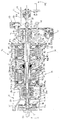
- Power train 10 which is of a hybrid type, comprises a diesel engine 11 (not shown) for rotating a shaft 17, and a number of units 12, 13, 14, 15, 16, the functions of which are explained in detail later on.
- Unit 12 is commonly known in the art, and comprises a first stage 12a for connecting/disconnecting diesel engine 11 to/from shaft 17. Stage 12a is engaged or released by the operator by means of a sleeve 18 and a lever 19 operated by further actuating means not shown. To engage and release stage 12a, sleeve 18 moves in a direction defined by an axis 20, which is also the longitudinal axis of symmetry of shaft 17.
- unit 12 Downstream of first stage 12a, unit 12 comprises a known second stage 12b comprising a clutch device 21 for connecting/disconnecting shaft 17 to/from a hollow shaft 22.
- a portion 21b of clutch device 21 by known means not shown, shaft 22, becoming integral with shaft 17, is rotated in the same direction as diesel engine 11.
- Both stages 12a, 12b are supported in a known manner by a support 27 preferably, though not necessarily, made of cast iron.
- Hollow shaft 22 houses, coaxially, a shaft 28 for powering a PTO. All shafts 17, 22, 28 have the same longitudinal axis of symmetry 20.
- Unit 13 comprises a first electric machine 29 housed in a structural casing 30, the casing 30 also housing an electric insulating element 31 on which rests a conventional stator 32.
- a rotor 33 of conventional configuration completes electric machine 29, and is defined by a pack of laminations 33a fitted to a shaft 34 supported on two ball bearings 35, 36a.
- Bearing 35 is housed in a seat 30a formed in a wall 30b of the structural casing
- bearing 36a is housed in a seat 37a formed in a plate 37 at an opening 37c.
- Structural casing 30 also advantageously, though not necessarily, made of cast iron, is bolted by known means on one side to support 27, and on the other to both plate 37 and a structural casing 38 forming part of the next unit 14. Being open on the side facing unit 14, structural casing 30 permits easy assembly of the component parts of electric machine 29.
- Two chambers 38a, 38b are defined inside structural casing 38 of unit 14, and are separated by a wall 39 having an opening 39a.
- the first chamber 38a houses an epicyclic gear train 40, the component parts of which and the way in which they are connected to the other parts of power train 10 are explained in detail later on.
- Structural casing 38 houses elements forming part of a second electric machine 41, which in principle comprises the same component parts as first electric machine 29.
- second electric machine 41 comprises an electric insulating element 42, on which rests a conventional stator 43, and is completed by a rotor 44 fitted to a shaft 45 supported on two ball bearings 46, 47.
- Shaft 45 is also hollow and coaxial with axis 20, and rotor 44 comprises a pack of laminations 44a.
- the first and second electric machines 29, 41 are connected to a battery pack (not shown).
- second chamber 38b is open, at least on one side, namely outwards towards the next unit 15, the component parts of second electric machine 41 are assembled easily inside second chamber 38b.
- actuating means operate lever 19 to engage/release sleeve 18, which can be released automatically when power train 10 is running, or manually by the user operating a lever (not shown) or a pedal (not shown) to start directly in fully electric mode when power train 10 is off.
- the tractor hydraulic circuit (not shown) is already pressurised so that enough hydraulic power is available to automatically release sleeve 18 to switch to fully electric mode.
- a manual control must be provided to release sleeve 18. Otherwise, operation of electric machines 29, 41 would rotate shaft 17, thus resulting in undesired start-up of diesel engine 11.
- Epicyclic gear train 40 comprises a planet carrier 40a integral with hollow shaft 22; and a number of planet wheels 40b, each connected to planet carrier 40a by a respective spindle 40c.
- Epicyclic gear train 40 further comprises a sun gear 40d integral with hollow shaft 34 of electric machine 29; and a ring gear 40e integral with hollow shaft 45 of second electric machine 41.
- epicyclic gear train 40 divides and recombines the mechanical power supplied by diesel engine 11, and the electric power produced by electric machines 29, 41.
- Hollow shaft 45 of second electric machine 41 acts as a real energy summing shaft in that it provides for actually adding the mechanical energy transmitted to it by ring gear 40e of epicyclic gear train 40 to the rotational energy supplied by rotor 44.
- structural casing 30, plate 37, and structural casing 38 are preferably made of cast iron and connected to one another by known fastening means, such as a number of bolts and respective nuts, so that the structural unit housing the two electric machines 29, 41 is extremely compact and solid.
- Bearing 46 is housed in a seat 46a formed in wall 39, close to opening 39a, whereas bearing 47 is housed in a seat 47a formed in a wall 48 of the next unit 15.
- the wall 48 has an opening 47b.
- Unit 15 comprises a structural casing 49 to which wall 48 belongs and housing a conventional high/low (HI/LO) transmission 50.
- HI/LO transmission 50 rotates a pinion 51 of the rear wheel differential (not shown).
- HI/LO transmission 50 comprises two clutch devices 50a, 50b, both for rotating a shaft 52 to which pinion 51 is fitted.
- Clutch device 50a substantially comprises a clutch and two gears 53, 54; gear 54 being fitted to shaft 52.
- device 50b comprises a clutch and two gears 55, 56.
- Gear 56 is also fitted to shaft 52, whereas gears 53 and 55 are fitted to a hollow shaft 53a.
- the angular speed of pinion 51 therefore depends on which of the two clutches is engaged, and therefore on which of the two pairs of gears 53, 54 or 55, 56 is rotating shaft 52.
- clutch device 50a when clutch device 50a is engaged, HI mode is selected and pinion 51 rotates at a high angular speed. In contrast, to rotate pinion 51 at low speed, clutch device 50a is simply released and device 50b engaged to select LO mode.
- Gear 56 always transmits motion to a known device 57 for transmitting motion to the front wheels (not shown).
- PTO shaft 28 rotates a gear 58 meshing with a gear 59 for transmitting motion to a shaft controlling auxiliary facilities 60 (shown only partly).
- shaft 28 is provided with a PTO clutch 61.
- Unit 16 is also housed in a structural casing 16a.
- Structural casings 49 and 16a are also advantageously made of cast iron.
Abstract
Description
- The present invention relates to a hybrid power train for farm tractors.
- In the state of the art, hybrid power trains are known in which part of the energy produced by an internal combustion engine is converted into electric energy to improve control of the power train.
- A hybrid power train of this type is described and claimed in EP-A-01203947.5 filed by the present Applicant, and to which the reader is referred for further details.
- One of the problems posed by this type of power train is its overall volume, which makes it unsuitable for use on farm tractors, in which available space is limited. Moreover, known hybrid power trains are difficult to produce and involve a large number of component parts.
- Known hybrid engines, in fact, comprise a housing containing the two electric motors/generators, each of which in turn comprises a respective casing.
- It is therefore an object of the present invention to provide a hybrid power train for a vehicle, which is more compact and easier to manufacture. This object is achieved in the present invention by replacing the electric motor casings with innovative structural casings. In a preferred embodiment, the casings advantageously are made of cast iron.
- In so doing, the power of the electric motors can also be increased for a given size of the overall power train. Combining increased electric power and compactness, hybrid power trains can therefore also be used to advantage on farm tractors.
- The present invention also provides a straightforward, effective solution to the problem of connecting the diesel engine mechanically to the power take-off (PTO) on the tractor, by routing the PTO shaft through a number of hollow shafts for transmitting power from the diesel engine, and to and from the two electric machines by means of a conventional epicyclic gear train.
- According to the present invention, therefore, there is provided a hybrid power train for a vehicle, as claimed in
Claim 1. - The present invention will now be described, by way of example, with reference to the accompanying drawing showing a non-limiting embodiment.
-
Number 10 in the accompanying drawing indicates the overall power train according to the present invention.Power train 10, which is of a hybrid type, comprises a diesel engine 11 (not shown) for rotating ashaft 17, and a number ofunits - Going over the accompanying drawing from left to right, the first unit shown is a connecting/disconnecting
unit 12.Unit 12 is commonly known in the art, and comprises afirst stage 12a for connecting/disconnectingdiesel engine 11 to/fromshaft 17.Stage 12a is engaged or released by the operator by means of asleeve 18 and alever 19 operated by further actuating means not shown. To engage and releasestage 12a,sleeve 18 moves in a direction defined by anaxis 20, which is also the longitudinal axis of symmetry ofshaft 17. - Downstream of
first stage 12a,unit 12 comprises a knownsecond stage 12b comprising aclutch device 21 for connecting/disconnectingshaft 17 to/from ahollow shaft 22. By activating aportion 21b of clutch device 21 (by known means not shown),shaft 22, becoming integral withshaft 17, is rotated in the same direction asdiesel engine 11. - Conversely, by activating a
portion 21a ofclutch device 21, the power generated bydiesel engine 11 is transmitted toshaft 22 in the opposite sense of rotation when compared to the former situation by a set of threeintermeshing gears gear 24 is idle), a shaft 25a, andgears 25c and 25b. - Both
stages support 27 preferably, though not necessarily, made of cast iron. -
Hollow shaft 22 houses, coaxially, ashaft 28 for powering a PTO. Allshafts symmetry 20. -
Unit 13 comprises a first electric machine 29 housed in astructural casing 30, thecasing 30 also housing anelectric insulating element 31 on which rests a conventional stator 32. A rotor 33 of conventional configuration completes electric machine 29, and is defined by a pack oflaminations 33a fitted to ashaft 34 supported on twoball bearings 35, 36a.Bearing 35 is housed in aseat 30a formed in awall 30b of the structural casing, and bearing 36a is housed in aseat 37a formed in a plate 37 at an opening 37c. -
Structural casing 30, also advantageously, though not necessarily, made of cast iron, is bolted by known means on one side to support 27, and on the other to both plate 37 and astructural casing 38 forming part of thenext unit 14. Being open on theside facing unit 14,structural casing 30 permits easy assembly of the component parts of electric machine 29. - Two
chambers 38a, 38b are defined insidestructural casing 38 ofunit 14, and are separated by a wall 39 having an opening 39a. - The first chamber 38a houses an epicyclic gear train 40, the component parts of which and the way in which they are connected to the other parts of
power train 10 are explained in detail later on. -
Structural casing 38, and in particular thesecond chamber 38b, houses elements forming part of a second electric machine 41, which in principle comprises the same component parts as first electric machine 29. More particularly, second electric machine 41 comprises anelectric insulating element 42, on which rests a conventional stator 43, and is completed by a rotor 44 fitted to a shaft 45 supported on twoball bearings 46, 47. Shaft 45 is also hollow and coaxial withaxis 20, and rotor 44 comprises a pack oflaminations 44a. As is conventional, the first and second electric machines 29, 41 are connected to a battery pack (not shown). - Since also
second chamber 38b is open, at least on one side, namely outwards towards thenext unit 15, the component parts of second electric machine 41 are assembled easily insidesecond chamber 38b. - As stated, actuating means (not shown) operate
lever 19 to engage/releasesleeve 18, which can be released automatically whenpower train 10 is running, or manually by the user operating a lever (not shown) or a pedal (not shown) to start directly in fully electric mode whenpower train 10 is off. Whenpower train 10 is running, in fact, the tractor hydraulic circuit (not shown) is already pressurised so that enough hydraulic power is available to automatically releasesleeve 18 to switch to fully electric mode. Conversely, whenpower train 10 is off, no hydraulic power is available to start directly in fully electric mode, so a manual control must be provided to releasesleeve 18. Otherwise, operation of electric machines 29, 41 would rotateshaft 17, thus resulting in undesired start-up ofdiesel engine 11. - Epicyclic gear train 40 comprises a planet carrier 40a integral with
hollow shaft 22; and a number of planet wheels 40b, each connected to planet carrier 40a by arespective spindle 40c. Epicyclic gear train 40 further comprises asun gear 40d integral withhollow shaft 34 of electric machine 29; and aring gear 40e integral with hollow shaft 45 of second electric machine 41. - By means of known mechanisms described in EP-A-01203947.5, epicyclic gear train 40 divides and recombines the mechanical power supplied by
diesel engine 11, and the electric power produced by electric machines 29, 41. - Hollow shaft 45 of second electric machine 41 acts as a real energy summing shaft in that it provides for actually adding the mechanical energy transmitted to it by
ring gear 40e of epicyclic gear train 40 to the rotational energy supplied by rotor 44. - As already mentioned,
structural casing 30, plate 37, andstructural casing 38 are preferably made of cast iron and connected to one another by known fastening means, such as a number of bolts and respective nuts, so that the structural unit housing the two electric machines 29, 41 is extremely compact and solid. - Bearing 46 is housed in a seat 46a formed in wall 39, close to opening 39a, whereas bearing 47 is housed in a seat 47a formed in a wall 48 of the
next unit 15. The wall 48 has an opening 47b. -
Unit 15 comprises astructural casing 49 to which wall 48 belongs and housing a conventional high/low (HI/LO)transmission 50. HI/LO transmission 50 rotates apinion 51 of the rear wheel differential (not shown). - More specifically, HI/
LO transmission 50 comprises twoclutch devices shaft 52 to whichpinion 51 is fitted.Clutch device 50a substantially comprises a clutch and twogears gear 54 being fitted toshaft 52. Similarly,device 50b comprises a clutch and twogears 55, 56.Gear 56 is also fitted toshaft 52, whereasgears 53 and 55 are fitted to a hollow shaft 53a. The angular speed ofpinion 51 therefore depends on which of the two clutches is engaged, and therefore on which of the two pairs ofgears shaft 52. - In other words, when
clutch device 50a is engaged, HI mode is selected andpinion 51 rotates at a high angular speed. In contrast, to rotatepinion 51 at low speed,clutch device 50a is simply released anddevice 50b engaged to select LO mode. - Gear 56 always transmits motion to a
known device 57 for transmitting motion to the front wheels (not shown). - As shown in the accompanying drawing,
PTO shaft 28 rotates agear 58 meshing with agear 59 for transmitting motion to a shaft controlling auxiliary facilities 60 (shown only partly). - At
unit 16,shaft 28 is provided with aPTO clutch 61.Unit 16 is also housed in astructural casing 16a.Structural casings - Operation of the hybrid power train according to the present invention is described fully in EP-A-01203947.5 to which the reader is referred for further details.
- The advantages of the hybrid power train according to the present invention are as follows:
- greater compactness for industrial use on farm tractors; according to the present invention, this is achieved by replacing the electric motor casings with innovative structural vehicle casings advantageously made of cast iron, so that, for a given size of the power train, the power of the electric motors can be increased, and the hybrid power train also can be used to advantage on farm machinery;
- small number of easy-to-assemble component parts; assembly of the component parts of the electric machines in particular is greatly simplified;
- improved disposal of heat generated by the electric machines, either directly to the outside or by means of coolant circulated in channels formed in the structural casings; and
- straightforward, effective solution to the problem of connecting the diesel engine mechanically to the PTO of the tractor, by routing the PTO shaft through a number of hollow shafts for transmitting power from the diesel engine, and to and from the two electric machines by means of a conventional epicyclic gear train.
Claims (16)
- A hybrid power train (10) for a vehicle; the power train (10) comprising an internal combustion engine (11) and at least two electric machines (29, 41) which are connected mechanically to a device (40) for dividing/recombining the power generated by said engine (11) and generated/drawn by said electric machines (29, 41), so that said electric machines (29, 41) function both as generators and as motors;
characterized in that the active elements defining at least one of said electric machines (29; 41) are housed in a structural casing (30; 38) defining the structural body of the vehicle; said structural casing (30; 38) being formed in one piece and in the form of a half-shell open on one side, so as to permit assembly of an insulating element (31; 42), a stator (32; 43), and a shaft (34; 45) provided with a rotor (33; 44) to form said at least one electric machine (29, 41). - A power train (10) according to claim 1, characterized in that said device (40) for dividing/recombining the power generated by said engine (11) and generated/drawn by said electric machines (29, 41), is interposed between said electric machines (29, 41).
- A power train (10) according to claim 1 or 2, characterized in that said device (40) for dividing/recombining the power is housed in the same structural casing (30; 38) as one of the two electric machines (29; 41).
- A power train (10) according to any of the preceding claims, characterized in that said engine (11) is connected mechanically by a further shaft (22) to the planet carrier (40a) of said device (40); wherein a first (34) of said shafts (34, 45) of a first (29) of said electric machines (29, 41) is connected mechanically to a sun gear (40d) of said device (40); and wherein a second (45) of said shafts (34, 45) of a second (41) of said electric machines (29, 41) is connected mechanically to a ring gear (40e) of said device (40).
- A power train (10) according to claim 4, characterized in that said second shaft (45) of said second electric machine (41) adds up the energy transmitted mechanically to it by said ring gear (40e) to the rotational energy supplied by the rotor (44) of said second electric machine (41).
- A power train (10) according to claim 4 or 5, characterized in that said shafts (34, 45) and said further shaft (22) are coaxial with an axis (20), are hollow, and house a shaft (28) for powering a PTO.
- A power train (10) according to claims 4 to 6, characterized in that said further shaft (22) is housed in said shaft (34) provided with a rotor (33).
- A power train (10) according to any of the preceding claims, characterized in that the power train comprises a support (27) and a number of structural casings (30, 38, 49, 16a) made of cast iron.
- A power train (10) according to any of the preceding claims, characterized in that conduits for the cooling fluid of said electric machines (29; 41) are formed integrally in said structural casings (30; 38).
- A power train (10) according to any of the preceding claims, characterized in that actuating means are provided to engage/release a sleeve (18) for connecting/disconnecting a first part (11) of the power train (10) generating purely mechanical power to/from a second part (13, 14) generating purely electric power; said sleeve (18) being engageable/releasable on the one hand automatically when the power train (10) is running, or on the other hand manually by an operator when the power train (10) is not running enabling to start directly in fully electric operating mode.
- A power train according to any of the preceding claims, characterized in that the insulating element (31, 42) is provided inbetween said structural casing (30, 38) and said stator (32, 43).
- A power train according to any of the preceding claims, characterized in that the internal combustion engine (11) is a diesel engine.
- A power train according to any of the preceding claims, characterized in that the vehicle is an agricultural tractor.
- A power train according to any of the preceding claims, characterized in that an inverter (21) for changing the drive direction is provided inbetween said engine (11) and said at least two electric machines (29, 41).
- A power train according to claim 3 and any claim dependent therefrom, characterized in that a closure plate (37) is operable to close both said structural casing (30) housing said at least one of said electric machines (29) and said structural casing (38) housing said device (40) for dividing/recombining the power.
- A power train according to claim 3 and any claim dependent therefrom, characterized in that a separation wall (39), integral with said structural casing (38) containing said device (40) for dividing/recombining the power, is provided inbetween said device (40) and the electric machine (41) contained in said casing (38).
Applications Claiming Priority (2)
| Application Number | Priority Date | Filing Date | Title |
|---|---|---|---|
| ITBO20010734 | 2001-11-30 | ||
| IT2001BO000734A ITBO20010734A1 (en) | 2001-11-30 | 2001-11-30 | HYBRID PROPULSION GROUP FOR AGRICULTURAL TRACTORS |
Publications (3)
| Publication Number | Publication Date |
|---|---|
| EP1317050A2 true EP1317050A2 (en) | 2003-06-04 |
| EP1317050A3 EP1317050A3 (en) | 2006-05-24 |
| EP1317050B1 EP1317050B1 (en) | 2013-06-05 |
Family
ID=11439717
Family Applications (1)
| Application Number | Title | Priority Date | Filing Date |
|---|---|---|---|
| EP02079634.8A Expired - Lifetime EP1317050B1 (en) | 2001-11-30 | 2002-11-07 | Hybrid farm tractor power train |
Country Status (3)
| Country | Link |
|---|---|
| US (2) | US6899190B2 (en) |
| EP (1) | EP1317050B1 (en) |
| IT (1) | ITBO20010734A1 (en) |
Cited By (13)
| Publication number | Priority date | Publication date | Assignee | Title |
|---|---|---|---|---|
| US6899190B2 (en) | 2001-11-30 | 2005-05-31 | Cnh America Llc | Tractor powertrain including plurality of structural casings |
| WO2006097818A1 (en) * | 2005-03-15 | 2006-09-21 | Toyota Jidosha Kabushiki Kaisha | Drive unit and vehicle including the same |
| WO2007000848A1 (en) * | 2005-06-27 | 2007-01-04 | Toyota Jidosha Kabushiki Kaisha | Power transmission apparatus of hybrid vehicle |
| WO2007017719A2 (en) * | 2005-08-05 | 2007-02-15 | Bordini Engineering Srl | Hybrid traction system |
| EP1894764A1 (en) * | 2005-06-24 | 2008-03-05 | Toyota Jidosha Kabushiki Kaisha | Drive device for vehicle and method of assembling the same |
| EP1944526A1 (en) * | 2005-10-26 | 2008-07-16 | Aisin Aw Co., Ltd. | Hybrid drive device |
| WO2008122862A1 (en) * | 2007-04-05 | 2008-10-16 | Bordini Engineering Srl | Hybrid traction system |
| CN101203396B (en) * | 2005-06-24 | 2010-06-16 | 丰田自动车株式会社 | Drive device for vehicle and method of assembling the same |
| DE102016204727A1 (en) * | 2016-03-22 | 2017-09-28 | Zf Friedrichshafen Ag | Continuously power split transmission with at least one driving range |
| DE102016204725A1 (en) * | 2016-03-22 | 2017-09-28 | Zf Friedrichshafen Ag | Continuously power split transmission with at least one driving range |
| WO2019100133A1 (en) * | 2017-11-27 | 2019-05-31 | CNH Industrial Brasil Ltda. | Power transmission unit for shafts and vehicles for carrying passengers and goods |
| IT201900004719A1 (en) * | 2019-03-29 | 2020-09-29 | Ecothea S R L | Hybrid transmission group for a tractor and tractor including this group |
| WO2023067494A1 (en) * | 2021-10-18 | 2023-04-27 | Ecothea S.R.L. | Electric traction motor unit, drive unit and agricultural vehicle comprising the same, and electric traction kit and assembly method thereof |
Families Citing this family (28)
| Publication number | Priority date | Publication date | Assignee | Title |
|---|---|---|---|---|
| DE10248715A1 (en) * | 2002-10-18 | 2004-05-13 | Compact Dynamics Gmbh | Hybrid drive for a motor vehicle |
| JP4233338B2 (en) * | 2003-01-30 | 2009-03-04 | 株式会社 神崎高級工機製作所 | Vehicle frame structure |
| US7364409B2 (en) * | 2004-02-11 | 2008-04-29 | Haldex Hydraulics Corporation | Piston assembly for rotary hydraulic machines |
| US7380490B2 (en) * | 2004-02-11 | 2008-06-03 | Haldex Hydraulics Corporation | Housing for rotary hydraulic machines |
| US7402027B2 (en) * | 2004-02-11 | 2008-07-22 | Haldex Hydraulics Corporation | Rotating group of a hydraulic machine |
| US7086225B2 (en) * | 2004-02-11 | 2006-08-08 | Haldex Hydraulics Corporation | Control valve supply for rotary hydraulic machine |
| WO2006030948A1 (en) * | 2004-09-14 | 2006-03-23 | Toyota Jidosha Kabushiki Kaisha | Drive device for vehicle |
| WO2006035981A1 (en) * | 2004-09-27 | 2006-04-06 | Toyota Jidosha Kabushiki Kaisha | Drive device for vehicle |
| US7357203B2 (en) * | 2004-09-28 | 2008-04-15 | Oshkosh Truck Corporation | Self-contained axle module |
| US8561735B2 (en) * | 2004-09-28 | 2013-10-22 | Oshkosh Corporation | Self-contained axle module |
| US7448460B2 (en) | 2004-09-28 | 2008-11-11 | Oshkosh Corporation | Power takeoff for an electric vehicle |
| JP4059876B2 (en) * | 2004-10-14 | 2008-03-12 | トヨタ自動車株式会社 | Hybrid drive device |
| US7753149B2 (en) * | 2004-11-22 | 2010-07-13 | Toyota Jidosha Kabushiki Kaisha | Vehicle driving apparatus |
| KR20070086781A (en) * | 2004-12-01 | 2007-08-27 | 할덱스 하이드럴릭스 코포레이션 | Hydraulic drive system |
| US7801653B2 (en) * | 2006-09-08 | 2010-09-21 | Deere & Company | System and method for boosting torque output of a drive train |
| US7949442B2 (en) * | 2006-09-08 | 2011-05-24 | Deere & Company | System and method for boosting torque output of a drive train |
| US7276806B1 (en) * | 2006-09-08 | 2007-10-02 | Deere & Company | System and method for boosting torque output of a drive train |
| US8478466B2 (en) * | 2007-12-27 | 2013-07-02 | Byd Co. Ltd. | Hybrid vehicle having multi-mode controller |
| US8104288B2 (en) * | 2008-09-25 | 2012-01-31 | Honeywell International Inc. | Effusion cooling techniques for combustors in engine assemblies |
| US8701806B2 (en) * | 2009-03-18 | 2014-04-22 | Kanzaki Kokyukoki Mfg. Co., Ltd. | Electric transaxle unit |
| GB201007566D0 (en) * | 2010-05-06 | 2010-06-23 | Agco Sa | Tractor with hybrid power system |
| DE102010017393B4 (en) | 2010-06-16 | 2023-02-16 | Dr. Ing. H.C. F. Porsche Aktiengesellschaft | powertrain and chassis |
| DE102012024452A1 (en) * | 2011-12-15 | 2013-06-20 | Bomag Gmbh | A construction machine or agricultural machine with a rotating working device and method for driving the rotating Arbeitseinrchtung |
| DE102012011573A1 (en) * | 2012-06-13 | 2013-12-19 | Claas Selbstfahrende Erntemaschinen Gmbh | Steering axle for agricultural vehicles |
| US9637000B2 (en) | 2012-11-06 | 2017-05-02 | Agco Sa | Tractor with hybrid power system |
| CN105576895A (en) * | 2015-04-17 | 2016-05-11 | 林天宇 | Energy-saving power generation device capable of improving generator efficiency |
| DE102017211711A1 (en) * | 2017-07-10 | 2019-01-10 | Ford Global Technologies, Llc | Hybrid powertrain for a motor vehicle |
| JP7070240B2 (en) * | 2018-08-23 | 2022-05-18 | トヨタ自動車株式会社 | Hybrid vehicle |
Citations (4)
| Publication number | Priority date | Publication date | Assignee | Title |
|---|---|---|---|---|
| GB1255036A (en) | 1968-11-19 | 1971-11-24 | British Motor Corp Ltd | Motor vehicles with hydrostatic power transmission |
| EP1092581A2 (en) | 1999-10-12 | 2001-04-18 | Toyota Jidosha Kabushiki Kaisha | Hybrid vehicle and method of controlling the same |
| DE10025089A1 (en) | 2000-05-20 | 2001-11-22 | Still Gmbh | Electric drive for fork lift vehicle, includes generator and travel motor assembled as common electro-converter unit in common casing |
| EP1203947A2 (en) | 2000-11-06 | 2002-05-08 | Kabushiki Kaisha Toshiba | Pattern detection, processing and testing apparatus |
Family Cites Families (14)
| Publication number | Priority date | Publication date | Assignee | Title |
|---|---|---|---|---|
| US3693035A (en) * | 1970-09-15 | 1972-09-19 | Black & Decker Mfg Co | Double insulated field mounting for universal motor |
| IT1228264B (en) * | 1987-07-10 | 1991-06-05 | Bcs Spa | VEHICLE FOR GARDENING AND AGRICULTURAL WORK |
| JP2967103B2 (en) * | 1993-05-24 | 1999-10-25 | 株式会社エクォス・リサーチ | Hybrid vehicle |
| JP3129204B2 (en) * | 1995-10-18 | 2001-01-29 | トヨタ自動車株式会社 | Hybrid drive |
| US6121707A (en) * | 1998-01-22 | 2000-09-19 | Reliance Electric Technologies, Llc | Electric motor and electric motor stator and method for making same |
| DE19841828C2 (en) * | 1998-09-12 | 2002-05-29 | Daimler Chrysler Ag | Hybrid drive, especially for vehicles |
| US6338391B1 (en) * | 1999-03-01 | 2002-01-15 | Paice Corporation | Hybrid vehicles incorporating turbochargers |
| JP2000324857A (en) * | 1999-03-11 | 2000-11-24 | Toyota Motor Corp | Variety of power units, and equipment, motor driver, and hybrid vehicle provided with the same |
| JP3654128B2 (en) * | 2000-04-06 | 2005-06-02 | 日産自動車株式会社 | Vehicle control device |
| JP4592143B2 (en) * | 2000-04-06 | 2010-12-01 | パナソニック株式会社 | Compressor and electric motor |
| JP4492989B2 (en) * | 2000-09-18 | 2010-06-30 | 株式会社 神崎高級工機製作所 | Shifting operation mechanism |
| ITBO20000607A1 (en) | 2000-10-18 | 2002-04-18 | New Holland Italia Spa | PROPULSION GROUP FOR A SELF-PROPELLED VEHICLE |
| US6453222B1 (en) * | 2000-10-31 | 2002-09-17 | Volvo Car Corporation | Method and arrangement in a hybrid vehicle for matching engine and generator torques at times of engagement and disengagement |
| ITBO20010734A1 (en) | 2001-11-30 | 2003-05-30 | New Holland Italia Spa | HYBRID PROPULSION GROUP FOR AGRICULTURAL TRACTORS |
-
2001
- 2001-11-30 IT IT2001BO000734A patent/ITBO20010734A1/en unknown
-
2002
- 2002-10-28 US US10/281,606 patent/US6899190B2/en not_active Expired - Lifetime
- 2002-11-07 EP EP02079634.8A patent/EP1317050B1/en not_active Expired - Lifetime
-
2004
- 2004-10-28 US US10/976,017 patent/US20050150700A1/en not_active Abandoned
Patent Citations (4)
| Publication number | Priority date | Publication date | Assignee | Title |
|---|---|---|---|---|
| GB1255036A (en) | 1968-11-19 | 1971-11-24 | British Motor Corp Ltd | Motor vehicles with hydrostatic power transmission |
| EP1092581A2 (en) | 1999-10-12 | 2001-04-18 | Toyota Jidosha Kabushiki Kaisha | Hybrid vehicle and method of controlling the same |
| DE10025089A1 (en) | 2000-05-20 | 2001-11-22 | Still Gmbh | Electric drive for fork lift vehicle, includes generator and travel motor assembled as common electro-converter unit in common casing |
| EP1203947A2 (en) | 2000-11-06 | 2002-05-08 | Kabushiki Kaisha Toshiba | Pattern detection, processing and testing apparatus |
Cited By (24)
| Publication number | Priority date | Publication date | Assignee | Title |
|---|---|---|---|---|
| US6899190B2 (en) | 2001-11-30 | 2005-05-31 | Cnh America Llc | Tractor powertrain including plurality of structural casings |
| KR100904968B1 (en) * | 2005-03-15 | 2009-06-26 | 도요타 지도샤(주) | Drive unit and vehicle including the same |
| WO2006097818A1 (en) * | 2005-03-15 | 2006-09-21 | Toyota Jidosha Kabushiki Kaisha | Drive unit and vehicle including the same |
| US7811190B2 (en) | 2005-06-24 | 2010-10-12 | Toyota Jidsoha Kabushiki Kaisha | Drive device for vehicle and method of assembling the same |
| EP1894764A1 (en) * | 2005-06-24 | 2008-03-05 | Toyota Jidosha Kabushiki Kaisha | Drive device for vehicle and method of assembling the same |
| EP1894764A4 (en) * | 2005-06-24 | 2008-07-02 | Toyota Motor Co Ltd | Drive device for vehicle and method of assembling the same |
| CN101203396B (en) * | 2005-06-24 | 2010-06-16 | 丰田自动车株式会社 | Drive device for vehicle and method of assembling the same |
| US8142317B2 (en) | 2005-06-27 | 2012-03-27 | Toyota Jidosha Kabushiki Kaisha | Power transmission apparatus of hybrid vehicle |
| JP2007039000A (en) * | 2005-06-27 | 2007-02-15 | Toyota Motor Corp | Power transmission apparatus of hybrid vehicle |
| WO2007000848A1 (en) * | 2005-06-27 | 2007-01-04 | Toyota Jidosha Kabushiki Kaisha | Power transmission apparatus of hybrid vehicle |
| WO2007017719A3 (en) * | 2005-08-05 | 2007-04-26 | Bordini Engineering Srl | Hybrid traction system |
| WO2007017719A2 (en) * | 2005-08-05 | 2007-02-15 | Bordini Engineering Srl | Hybrid traction system |
| US8091660B2 (en) | 2005-08-05 | 2012-01-10 | Bordini Engineering S.R.L. | Hybrid traction system |
| CN101272925B (en) * | 2005-08-05 | 2012-03-21 | 博尔迪尼工程有限责任公司 | Hybrid traction system |
| EP1944526A1 (en) * | 2005-10-26 | 2008-07-16 | Aisin Aw Co., Ltd. | Hybrid drive device |
| EP1944526A4 (en) * | 2005-10-26 | 2010-12-01 | Aisin Aw Co | Hybrid drive device |
| WO2008122862A1 (en) * | 2007-04-05 | 2008-10-16 | Bordini Engineering Srl | Hybrid traction system |
| DE102016204727A1 (en) * | 2016-03-22 | 2017-09-28 | Zf Friedrichshafen Ag | Continuously power split transmission with at least one driving range |
| DE102016204725A1 (en) * | 2016-03-22 | 2017-09-28 | Zf Friedrichshafen Ag | Continuously power split transmission with at least one driving range |
| WO2019100133A1 (en) * | 2017-11-27 | 2019-05-31 | CNH Industrial Brasil Ltda. | Power transmission unit for shafts and vehicles for carrying passengers and goods |
| US11571962B2 (en) | 2017-11-27 | 2023-02-07 | Iveco S.P.A. | Power transmission unit for shafts and vehicle for carrying passengers and goods |
| IT201900004719A1 (en) * | 2019-03-29 | 2020-09-29 | Ecothea S R L | Hybrid transmission group for a tractor and tractor including this group |
| WO2020201978A1 (en) * | 2019-03-29 | 2020-10-08 | Ecothea S.R.L. | Hybrid transmission unit for a tractor and tractor comprising the same |
| WO2023067494A1 (en) * | 2021-10-18 | 2023-04-27 | Ecothea S.R.L. | Electric traction motor unit, drive unit and agricultural vehicle comprising the same, and electric traction kit and assembly method thereof |
Also Published As
| Publication number | Publication date |
|---|---|
| US20050150700A1 (en) | 2005-07-14 |
| ITBO20010734A0 (en) | 2001-11-30 |
| ITBO20010734A1 (en) | 2003-05-30 |
| EP1317050B1 (en) | 2013-06-05 |
| US20030102174A1 (en) | 2003-06-05 |
| EP1317050A3 (en) | 2006-05-24 |
| US6899190B2 (en) | 2005-05-31 |
Similar Documents
| Publication | Publication Date | Title |
|---|---|---|
| EP1317050B1 (en) | Hybrid farm tractor power train | |
| US7238132B2 (en) | Electrically variable transmission arrangement with transfer gear between motor/generators | |
| JP3525412B2 (en) | Hybrid drive | |
| US7220200B2 (en) | Electrically variable transmission arrangement with spaced-apart simple planetary gear sets | |
| US7261660B2 (en) | Electrically variable transmission arrangement with transfer gear between gear sets and clutches | |
| US10124668B2 (en) | Center differential gear assembly for a drive device of a motor vehicle | |
| JP3536837B2 (en) | Drive unit for hybrid vehicle | |
| JP4234947B2 (en) | Drive unit for hydraulic pressure generator | |
| CN107199874B (en) | Drive assembly for hybrid vehicle | |
| US7222686B2 (en) | Drive train for series/parallel hybrid vehicle | |
| GB2290363A (en) | Drive unit | |
| US11173779B2 (en) | Drive unit for a powertrain of an electrically driveable motor vehicle, and drive assembly | |
| JP2015521255A (en) | Electric axle | |
| KR20220088491A (en) | drive unit and drive assembly | |
| JP2004353780A (en) | Driving device for vehicle, and fr type hybrid automobile loading the same | |
| FR2781727B1 (en) | HYBRID DRIVE GROUP COMPRISING TWO ELECTRIC MACHINES | |
| CN112368166A (en) | Drive unit and drive assembly for a drive train of an electrically driven motor vehicle | |
| US20230322071A1 (en) | Drive unit and drive assembly | |
| JP2007153114A (en) | Driving device of hybrid vehicle | |
| CN112141074B (en) | hybrid vehicle | |
| US4896550A (en) | Construction of starter motor for taking off power to outside | |
| JP3373082B2 (en) | Hybrid vehicle | |
| JP2023503681A (en) | Straddle-type hybrid propulsion vehicle | |
| JP2004114945A (en) | Driving device for vehicle and its assembling method | |
| JP2001161104A (en) | Hybrid tending machine |
Legal Events
| Date | Code | Title | Description |
|---|---|---|---|
| PUAI | Public reference made under article 153(3) epc to a published international application that has entered the european phase |
Free format text: ORIGINAL CODE: 0009012 |
|
| AK | Designated contracting states |
Designated state(s): AT BE BG CH CY CZ DE DK EE ES FI FR GB GR IE IT LI LU MC NL PT SE SK TR |
|
| AX | Request for extension of the european patent |
Extension state: AL LT LV MK RO SI |
|
| PUAL | Search report despatched |
Free format text: ORIGINAL CODE: 0009013 |
|
| AK | Designated contracting states |
Kind code of ref document: A3 Designated state(s): AT BE BG CH CY CZ DE DK EE ES FI FR GB GR IE IT LI LU MC NL PT SE SK TR |
|
| AX | Request for extension of the european patent |
Extension state: AL LT LV MK RO SI |
|
| 17P | Request for examination filed |
Effective date: 20061026 |
|
| AKX | Designation fees paid |
Designated state(s): AT BE BG CH CY CZ DE DK EE ES FI FR GB GR IE IT LI LU MC NL PT SE SK TR |
|
| RAP1 | Party data changed (applicant data changed or rights of an application transferred) |
Owner name: CNH ITALIA S.P.A. |
|
| RAP1 | Party data changed (applicant data changed or rights of an application transferred) |
Owner name: CNH ITALIA S.P.A. |
|
| 17Q | First examination report despatched |
Effective date: 20110126 |
|
| REG | Reference to a national code |
Ref country code: DE Ref legal event code: R079 Ref document number: 60245060 Country of ref document: DE Free format text: PREVIOUS MAIN CLASS: H02K0007180000 Ipc: H02K0007000000 |
|
| RIC1 | Information provided on ipc code assigned before grant |
Ipc: H02K 1/18 20060101ALI20120224BHEP Ipc: B60K 6/405 20071001ALI20120224BHEP Ipc: B60K 6/445 20071001ALI20120224BHEP Ipc: B60K 6/387 20071001ALI20120224BHEP Ipc: B60K 6/365 20071001ALI20120224BHEP Ipc: F16H 3/72 20060101ALI20120224BHEP Ipc: H02K 7/18 20060101ALI20120224BHEP Ipc: H02K 7/00 20060101AFI20120224BHEP |
|
| GRAP | Despatch of communication of intention to grant a patent |
Free format text: ORIGINAL CODE: EPIDOSNIGR1 |
|
| GRAS | Grant fee paid |
Free format text: ORIGINAL CODE: EPIDOSNIGR3 |
|
| GRAA | (expected) grant |
Free format text: ORIGINAL CODE: 0009210 |
|
| AK | Designated contracting states |
Kind code of ref document: B1 Designated state(s): AT BE BG CH CY CZ DE DK EE ES FI FR GB GR IE IT LI LU MC NL PT SE SK TR |
|
| REG | Reference to a national code |
Ref country code: GB Ref legal event code: FG4D |
|
| REG | Reference to a national code |
Ref country code: CH Ref legal event code: EP |
|
| REG | Reference to a national code |
Ref country code: AT Ref legal event code: REF Ref document number: 616160 Country of ref document: AT Kind code of ref document: T Effective date: 20130615 |
|
| REG | Reference to a national code |
Ref country code: IE Ref legal event code: FG4D |
|
| REG | Reference to a national code |
Ref country code: DE Ref legal event code: R096 Ref document number: 60245060 Country of ref document: DE Effective date: 20130801 |
|
| REG | Reference to a national code |
Ref country code: AT Ref legal event code: MK05 Ref document number: 616160 Country of ref document: AT Kind code of ref document: T Effective date: 20130605 |
|
| PG25 | Lapsed in a contracting state [announced via postgrant information from national office to epo] |
Ref country code: FI Free format text: LAPSE BECAUSE OF FAILURE TO SUBMIT A TRANSLATION OF THE DESCRIPTION OR TO PAY THE FEE WITHIN THE PRESCRIBED TIME-LIMIT Effective date: 20130605 Ref country code: ES Free format text: LAPSE BECAUSE OF FAILURE TO SUBMIT A TRANSLATION OF THE DESCRIPTION OR TO PAY THE FEE WITHIN THE PRESCRIBED TIME-LIMIT Effective date: 20130916 Ref country code: GR Free format text: LAPSE BECAUSE OF FAILURE TO SUBMIT A TRANSLATION OF THE DESCRIPTION OR TO PAY THE FEE WITHIN THE PRESCRIBED TIME-LIMIT Effective date: 20130906 Ref country code: AT Free format text: LAPSE BECAUSE OF FAILURE TO SUBMIT A TRANSLATION OF THE DESCRIPTION OR TO PAY THE FEE WITHIN THE PRESCRIBED TIME-LIMIT Effective date: 20130605 Ref country code: SE Free format text: LAPSE BECAUSE OF FAILURE TO SUBMIT A TRANSLATION OF THE DESCRIPTION OR TO PAY THE FEE WITHIN THE PRESCRIBED TIME-LIMIT Effective date: 20130605 |
|
| REG | Reference to a national code |
Ref country code: NL Ref legal event code: VDEP Effective date: 20130605 |
|
| PG25 | Lapsed in a contracting state [announced via postgrant information from national office to epo] |
Ref country code: BG Free format text: LAPSE BECAUSE OF FAILURE TO SUBMIT A TRANSLATION OF THE DESCRIPTION OR TO PAY THE FEE WITHIN THE PRESCRIBED TIME-LIMIT Effective date: 20130905 |
|
| PG25 | Lapsed in a contracting state [announced via postgrant information from national office to epo] |
Ref country code: SK Free format text: LAPSE BECAUSE OF FAILURE TO SUBMIT A TRANSLATION OF THE DESCRIPTION OR TO PAY THE FEE WITHIN THE PRESCRIBED TIME-LIMIT Effective date: 20130605 Ref country code: EE Free format text: LAPSE BECAUSE OF FAILURE TO SUBMIT A TRANSLATION OF THE DESCRIPTION OR TO PAY THE FEE WITHIN THE PRESCRIBED TIME-LIMIT Effective date: 20130605 Ref country code: CZ Free format text: LAPSE BECAUSE OF FAILURE TO SUBMIT A TRANSLATION OF THE DESCRIPTION OR TO PAY THE FEE WITHIN THE PRESCRIBED TIME-LIMIT Effective date: 20130605 Ref country code: PT Free format text: LAPSE BECAUSE OF FAILURE TO SUBMIT A TRANSLATION OF THE DESCRIPTION OR TO PAY THE FEE WITHIN THE PRESCRIBED TIME-LIMIT Effective date: 20131007 Ref country code: BE Free format text: LAPSE BECAUSE OF FAILURE TO SUBMIT A TRANSLATION OF THE DESCRIPTION OR TO PAY THE FEE WITHIN THE PRESCRIBED TIME-LIMIT Effective date: 20130605 |
|
| PG25 | Lapsed in a contracting state [announced via postgrant information from national office to epo] |
Ref country code: NL Free format text: LAPSE BECAUSE OF FAILURE TO SUBMIT A TRANSLATION OF THE DESCRIPTION OR TO PAY THE FEE WITHIN THE PRESCRIBED TIME-LIMIT Effective date: 20130605 |
|
| PLBE | No opposition filed within time limit |
Free format text: ORIGINAL CODE: 0009261 |
|
| STAA | Information on the status of an ep patent application or granted ep patent |
Free format text: STATUS: NO OPPOSITION FILED WITHIN TIME LIMIT |
|
| PG25 | Lapsed in a contracting state [announced via postgrant information from national office to epo] |
Ref country code: DK Free format text: LAPSE BECAUSE OF FAILURE TO SUBMIT A TRANSLATION OF THE DESCRIPTION OR TO PAY THE FEE WITHIN THE PRESCRIBED TIME-LIMIT Effective date: 20130605 |
|
| 26N | No opposition filed |
Effective date: 20140306 |
|
| REG | Reference to a national code |
Ref country code: DE Ref legal event code: R097 Ref document number: 60245060 Country of ref document: DE Effective date: 20140306 |
|
| REG | Reference to a national code |
Ref country code: DE Ref legal event code: R082 Ref document number: 60245060 Country of ref document: DE Representative=s name: PATENTANWAELTE WALLACH, KOCH & PARTNER, DE |
|
| REG | Reference to a national code |
Ref country code: CH Ref legal event code: PL |
|
| PG25 | Lapsed in a contracting state [announced via postgrant information from national office to epo] |
Ref country code: MC Free format text: LAPSE BECAUSE OF FAILURE TO SUBMIT A TRANSLATION OF THE DESCRIPTION OR TO PAY THE FEE WITHIN THE PRESCRIBED TIME-LIMIT Effective date: 20130605 Ref country code: LI Free format text: LAPSE BECAUSE OF NON-PAYMENT OF DUE FEES Effective date: 20131130 Ref country code: CH Free format text: LAPSE BECAUSE OF NON-PAYMENT OF DUE FEES Effective date: 20131130 |
|
| REG | Reference to a national code |
Ref country code: DE Ref legal event code: R081 Ref document number: 60245060 Country of ref document: DE Owner name: CNH INDUSTRIAL ITALIA S.P.A., IT Free format text: FORMER OWNER: CNH ITALIA S.P.A., MODENA, IT Effective date: 20130606 Ref country code: DE Ref legal event code: R082 Ref document number: 60245060 Country of ref document: DE Representative=s name: PATENTANWAELTE WALLACH, KOCH & PARTNER, DE Effective date: 20140623 Ref country code: DE Ref legal event code: R081 Ref document number: 60245060 Country of ref document: DE Owner name: CNH INDUSTRIAL ITALIA S.P.A., IT Free format text: FORMER OWNER: CNH ITALIA S.P.A., TORINO, IT Effective date: 20140623 Ref country code: DE Ref legal event code: R082 Ref document number: 60245060 Country of ref document: DE Representative=s name: PATENTANWAELTE WALLACH, KOCH, DR. HAIBACH, FEL, DE Effective date: 20140623 |
|
| REG | Reference to a national code |
Ref country code: IE Ref legal event code: MM4A |
|
| PG25 | Lapsed in a contracting state [announced via postgrant information from national office to epo] |
Ref country code: IE Free format text: LAPSE BECAUSE OF NON-PAYMENT OF DUE FEES Effective date: 20131107 |
|
| REG | Reference to a national code |
Ref country code: FR Ref legal event code: CD Owner name: CNH INDUSTRIAL ITALIA S.P.A. Effective date: 20150313 |
|
| PG25 | Lapsed in a contracting state [announced via postgrant information from national office to epo] |
Ref country code: CY Free format text: LAPSE BECAUSE OF FAILURE TO SUBMIT A TRANSLATION OF THE DESCRIPTION OR TO PAY THE FEE WITHIN THE PRESCRIBED TIME-LIMIT Effective date: 20130605 Ref country code: TR Free format text: LAPSE BECAUSE OF FAILURE TO SUBMIT A TRANSLATION OF THE DESCRIPTION OR TO PAY THE FEE WITHIN THE PRESCRIBED TIME-LIMIT Effective date: 20130605 |
|
| PG25 | Lapsed in a contracting state [announced via postgrant information from national office to epo] |
Ref country code: LU Free format text: LAPSE BECAUSE OF NON-PAYMENT OF DUE FEES Effective date: 20131107 |
|
| REG | Reference to a national code |
Ref country code: FR Ref legal event code: PLFP Year of fee payment: 14 |
|
| REG | Reference to a national code |
Ref country code: FR Ref legal event code: PLFP Year of fee payment: 15 |
|
| REG | Reference to a national code |
Ref country code: FR Ref legal event code: PLFP Year of fee payment: 16 |
|
| REG | Reference to a national code |
Ref country code: FR Ref legal event code: PLFP Year of fee payment: 17 |
|
| PGFP | Annual fee paid to national office [announced via postgrant information from national office to epo] |
Ref country code: ES Payment date: 20181127 Year of fee payment: 12 |
|
| PGFP | Annual fee paid to national office [announced via postgrant information from national office to epo] |
Ref country code: DE Payment date: 20191128 Year of fee payment: 18 |
|
| PGFP | Annual fee paid to national office [announced via postgrant information from national office to epo] |
Ref country code: FR Payment date: 20191124 Year of fee payment: 18 |
|
| PGFP | Annual fee paid to national office [announced via postgrant information from national office to epo] |
Ref country code: GB Payment date: 20191122 Year of fee payment: 18 |
|
| REG | Reference to a national code |
Ref country code: DE Ref legal event code: R082 Ref document number: 60245060 Country of ref document: DE Representative=s name: MEISSNER BOLTE PATENTANWAELTE RECHTSANWAELTE P, DE |
|
| PG25 | Lapsed in a contracting state [announced via postgrant information from national office to epo] |
Ref country code: IT Free format text: LAPSE BECAUSE OF NON-PAYMENT OF DUE FEES Effective date: 20191107 |
|
| REG | Reference to a national code |
Ref country code: DE Ref legal event code: R119 Ref document number: 60245060 Country of ref document: DE |
|
| GBPC | Gb: european patent ceased through non-payment of renewal fee |
Effective date: 20201107 |
|
| PG25 | Lapsed in a contracting state [announced via postgrant information from national office to epo] |
Ref country code: FR Free format text: LAPSE BECAUSE OF NON-PAYMENT OF DUE FEES Effective date: 20201130 |
|
| PG25 | Lapsed in a contracting state [announced via postgrant information from national office to epo] |
Ref country code: GB Free format text: LAPSE BECAUSE OF NON-PAYMENT OF DUE FEES Effective date: 20201107 Ref country code: DE Free format text: LAPSE BECAUSE OF NON-PAYMENT OF DUE FEES Effective date: 20210601 |