EP1317045B1 - Battery power source device and current detection method therefor - Google Patents
Battery power source device and current detection method therefor Download PDFInfo
- Publication number
- EP1317045B1 EP1317045B1 EP02258186A EP02258186A EP1317045B1 EP 1317045 B1 EP1317045 B1 EP 1317045B1 EP 02258186 A EP02258186 A EP 02258186A EP 02258186 A EP02258186 A EP 02258186A EP 1317045 B1 EP1317045 B1 EP 1317045B1
- Authority
- EP
- European Patent Office
- Prior art keywords
- battery
- battery pack
- current
- electronic control
- charge
- Prior art date
- Legal status (The legal status is an assumption and is not a legal conclusion. Google has not performed a legal analysis and makes no representation as to the accuracy of the status listed.)
- Expired - Lifetime
Links
Images


Classifications
-
- H—ELECTRICITY
- H02—GENERATION; CONVERSION OR DISTRIBUTION OF ELECTRIC POWER
- H02J—ELECTRIC POWER NETWORKS; CIRCUIT ARRANGEMENTS OR SYSTEMS FOR SUPPLYING OR DISTRIBUTING ELECTRIC POWER; SYSTEMS FOR STORING ELECTRIC ENERGY
- H02J7/00—Circuit arrangements for charging or discharging batteries or for supplying loads from batteries
- H02J7/50—Circuit arrangements for charging or discharging batteries or for supplying loads from batteries acting upon multiple batteries simultaneously or sequentially
- H02J7/575—Parallel/serial switching of connection of batteries to charge or load circuit
-
- G—PHYSICS
- G01—MEASURING; TESTING
- G01R—MEASURING ELECTRIC VARIABLES; MEASURING MAGNETIC VARIABLES
- G01R19/00—Arrangements for measuring currents or voltages or for indicating presence or sign thereof
- G01R19/165—Indicating that current or voltage is either above or below a predetermined value or within or outside a predetermined range of values
- G01R19/16533—Indicating that current or voltage is either above or below a predetermined value or within or outside a predetermined range of values characterised by the application
- G01R19/16538—Indicating that current or voltage is either above or below a predetermined value or within or outside a predetermined range of values characterised by the application in AC or DC supplies
- G01R19/16542—Indicating that current or voltage is either above or below a predetermined value or within or outside a predetermined range of values characterised by the application in AC or DC supplies for batteries
-
- G—PHYSICS
- G01—MEASURING; TESTING
- G01R—MEASURING ELECTRIC VARIABLES; MEASURING MAGNETIC VARIABLES
- G01R31/00—Arrangements for testing electric properties; Arrangements for locating electric faults; Arrangements for electrical testing characterised by what is being tested not provided for elsewhere
- G01R31/36—Arrangements for testing, measuring or monitoring the electrical condition of accumulators or electric batteries, e.g. capacity or state of charge [SoC]
- G01R31/382—Arrangements for monitoring battery or accumulator variables, e.g. SoC
- G01R31/3828—Arrangements for monitoring battery or accumulator variables, e.g. SoC using current integration
-
- G—PHYSICS
- G01—MEASURING; TESTING
- G01R—MEASURING ELECTRIC VARIABLES; MEASURING MAGNETIC VARIABLES
- G01R31/00—Arrangements for testing electric properties; Arrangements for locating electric faults; Arrangements for electrical testing characterised by what is being tested not provided for elsewhere
- G01R31/36—Arrangements for testing, measuring or monitoring the electrical condition of accumulators or electric batteries, e.g. capacity or state of charge [SoC]
- G01R31/396—Acquisition or processing of data for testing or for monitoring individual cells or groups of cells within a battery
-
- H—ELECTRICITY
- H02—GENERATION; CONVERSION OR DISTRIBUTION OF ELECTRIC POWER
- H02J—ELECTRIC POWER NETWORKS; CIRCUIT ARRANGEMENTS OR SYSTEMS FOR SUPPLYING OR DISTRIBUTING ELECTRIC POWER; SYSTEMS FOR STORING ELECTRIC ENERGY
- H02J7/00—Circuit arrangements for charging or discharging batteries or for supplying loads from batteries
- H02J7/50—Circuit arrangements for charging or discharging batteries or for supplying loads from batteries acting upon multiple batteries simultaneously or sequentially
-
- H—ELECTRICITY
- H02—GENERATION; CONVERSION OR DISTRIBUTION OF ELECTRIC POWER
- H02J—ELECTRIC POWER NETWORKS; CIRCUIT ARRANGEMENTS OR SYSTEMS FOR SUPPLYING OR DISTRIBUTING ELECTRIC POWER; SYSTEMS FOR STORING ELECTRIC ENERGY
- H02J7/00—Circuit arrangements for charging or discharging batteries or for supplying loads from batteries
- H02J7/80—Circuit arrangements for charging or discharging batteries or for supplying loads from batteries including monitoring or indicating arrangements
-
- G—PHYSICS
- G01—MEASURING; TESTING
- G01R—MEASURING ELECTRIC VARIABLES; MEASURING MAGNETIC VARIABLES
- G01R31/00—Arrangements for testing electric properties; Arrangements for locating electric faults; Arrangements for electrical testing characterised by what is being tested not provided for elsewhere
- G01R31/36—Arrangements for testing, measuring or monitoring the electrical condition of accumulators or electric batteries, e.g. capacity or state of charge [SoC]
- G01R31/374—Arrangements for testing, measuring or monitoring the electrical condition of accumulators or electric batteries, e.g. capacity or state of charge [SoC] with means for correcting the measurement for temperature or ageing
-
- H—ELECTRICITY
- H02—GENERATION; CONVERSION OR DISTRIBUTION OF ELECTRIC POWER
- H02J—ELECTRIC POWER NETWORKS; CIRCUIT ARRANGEMENTS OR SYSTEMS FOR SUPPLYING OR DISTRIBUTING ELECTRIC POWER; SYSTEMS FOR STORING ELECTRIC ENERGY
- H02J7/00—Circuit arrangements for charging or discharging batteries or for supplying loads from batteries
- H02J7/80—Circuit arrangements for charging or discharging batteries or for supplying loads from batteries including monitoring or indicating arrangements
- H02J7/82—Control of state of charge [SOC]
-
- Y—GENERAL TAGGING OF NEW TECHNOLOGICAL DEVELOPMENTS; GENERAL TAGGING OF CROSS-SECTIONAL TECHNOLOGIES SPANNING OVER SEVERAL SECTIONS OF THE IPC; TECHNICAL SUBJECTS COVERED BY FORMER USPC CROSS-REFERENCE ART COLLECTIONS [XRACs] AND DIGESTS
- Y02—TECHNOLOGIES OR APPLICATIONS FOR MITIGATION OR ADAPTATION AGAINST CLIMATE CHANGE
- Y02T—CLIMATE CHANGE MITIGATION TECHNOLOGIES RELATED TO TRANSPORTATION
- Y02T10/00—Road transport of goods or passengers
- Y02T10/60—Other road transportation technologies with climate change mitigation effect
- Y02T10/70—Energy storage systems for electromobility, e.g. batteries
Definitions
- the present invention relates to a battery power source device including a plurality of battery pack blocks, each of which is constituted by connecting a plurality of rechargeable batteries in series, and battery ECUs for controlling the operation state of the battery pack blocks.
- the plurality of battery pack blocks are connected with one another in parallel or by a combination of serial connection and parallel connection (in series-parallel).
- the invention also relates to a current detection method therefor.
- a battery power source device applied as a power source for an electric vehicle or hybrid car must supply large electric power.
- the device is therefore configured as a battery pack system.
- a plurality of (six for example) rechargeable batteries are connected together in series to constitute a battery module, and a plurality of (30 for example) such battery modules are connected together in series to constitute a battery pack block.
- a battery ECU Electronic Control Unit
- the battery ECU detects the voltage, current, and temperature of each battery pack block and carry out abnormality detection and various control based on the detection results. To meet a demand for significantly large power for a large-sized vehicle, for example, connecting such battery pack systems together in series, parallel or in series-parallel has been considered.
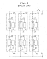
- Fig. 3 is a diagram showing the configuration of a battery power source device having six battery pack systems connected together in series-parallel.
- the battery pack systems all have the same arrangement including a battery pack block 21 and a battery ECU 22.
- the battery pack blocks 21 connected in series-parallel are each connected with a positive electrode charge/discharge terminal 23 and a negative electrode charge/discharge terminal 24.
- the operation state of each of the battery pack blocks 21 is monitored and controlled by the corresponding battery ECU 22.
- the battery pack block 21 is provided with sensors to detect voltage per battery module, charge/discharge current to/from the battery pack block 21, battery temperature per battery module, and the ambient temperature of the battery pack block 21, and the detection outputs of the sensors are input to the corresponding battery ECU 22.
- the battery ECU 22 monitors the operation state or abnormality of the battery pack block 21 based on the input voltage, current, and temperature detection outputs. Meanwhile, the battery ECU 22 controls a cooling device such as a blower fan provided at the battery pack block 21 based on the temperature detection output.
- the battery ECU 22 also calculates SOC (State Of Charge: accumulated electrical quantity relative to battery capacity) based on the voltage, current, and temperature detection outputs.
- SOC and the detection output such as voltage are externally output as the operation state data of the battery pack block 21, so as to be input to a vehicle ECU in a hybrid car for example and used for controlling charge/discharge to/from the battery power source device.
- the total charge/discharge current I can be detected by a special current sensor for high current provided at a charge/discharge circuit connected with the positive electrode charge/discharge terminal 23 or the negative electrode charge/discharge terminal 24 of the battery power source device.
- a special current sensor for high current provided at a charge/discharge circuit connected with the positive electrode charge/discharge terminal 23 or the negative electrode charge/discharge terminal 24 of the battery power source device.
- a processing circuit for processing and amplifying the detection output of the current sensor is necessary, which increases the cost.
- the battery pack blocks 21 are each provided with a current sensor 25, and the charge/discharge current is separately detected for each battery pack block 21 by the corresponding battery ECU 22. Consequently, when the charge/discharge current values at the battery pack blocks 21 connected in parallel are added up, the total charge/discharge current I should be produced. However, the detected current is used to calculate the SOC as described above.
- the current is input to the battery ECU 22, it is amplified by an amplification circuit 16, then A/D-converted by an A/D conversion circuit 17, and input to a microcomputer 18 for digital processing.
- the A/D-converted current data cannot be in synchronization with each other among the battery pack systems A1 to A6, and it is therefore impossible to produce the total charge/discharge current I simply by adding them up.
- US 5,504,415 discloses a method and an apparatus for equalizing the state of charge among a plurality of series-connected batteries.
- a module is connected in parallel with each of the batteries, respectively.
- Each module contains a voltage divider circuit so that the voltage across a battery may be measured to determine the state of charge, and a circuit which selectively shunts charging current around a battery or applies a discharging current to a battery.
- a charging transistor applies a charging current to the series of batteries and, depending upon the state of charge of each battery, a portion of the charging current may be shunted around the battery by its associated module so as to prevent overcharging of the battery.
- a controller monitors the state of charge of each of the batteries and a temperature of each of the batteries and adjusts the portion of the charging shunted around an individual battery so as to rapidly equalize to state of charge among the different batteries. Accordingly, this known arrangement does not detect a total charge/discharge current in a battery power source device including a plurality of battery pack systems connected in parallel or series-parallel.
- the charge acceptance parameter comprises a terminal voltage profile which is determined during a variation in a diagnostic current.
- the slope of the terminal voltage profile is used in the charging process to assess the charge acceptance ability of the battery and thereby control the charging current.
- the terminal voltage profile is characterised by an increasing profile slope as the charge acceptance ability of the battery is reached.
- the terminal voltage profile is characterized by a profile slope which approaches zero as the charge acceptance ability of the battery is reached.
- the present invention is directed to a method for detecting a total charge/discharge current in a battery power source device.
- the battery power source device includes a plurality of battery pack systems connected in parallel.
- Each of the battery pack systems includes a battery pack block having a plurality of rechargeable batteries connected in series; a battery electronic control unit that detects a current, a voltage, and a temperature and controls an operation state of the battery pack block based on the detection result; and a charge/discharge circuit for connecting the battery pack block.
- the method for detecting a total charge/discharge current includes detecting currents at the respective charge/discharge circuits of the battery pack systems detected by the corresponding battery electronic control units provided at the battery pack systems connected in parallel; and adding up the currents in an analog data state by an addition unit comprised in the battery electronic control unit.
- the total charge/discharge current in the battery power source device is obtained without having to provide current detection means and a processing circuit.
- Current data after A/D conversion may not accurately be added, while analog data before A/D conversion are accurately added. Consequently, charge/discharge currents detected by the battery ECUs in the battery pack systems connected in parallel can be added up to obtain the total charge/discharge current in the battery power source device.
- An implementation of the invention is directed to a battery power source device, comprising a plurality of battery pack systems connected in parallel.
- the battery pack systems each includes a battery pack block having a plurality of rechargeable batteries connected in series; a battery electronic control unit for detecting a current, a voltage, and a temperature and for controlling an operation state of the battery pack block based on the detection result; and a charge/discharge circuit for connecting the battery pack block, the charge/discharge circuit including a current sensor.
- the battery electronic control unit includes an amplification circuit for processing and amplifying a current detection output from the current sensor, and an A/D conversion circuit for receiving and A/D-converting an output value from the amplification circuit for output as a detection value for the current to be used for controlling an operation state of the battery pack system.
- the power source device further includes an addition unit for adding up the output values of the amplification circuits of the battery electronic control units in the battery pack systems connected in parallel to detect the total charge/discharge current value.
- the addition unit collects and adds up the output values of the amplification circuits of the battery electronic control units provided at the battery pack systems connected in parallel.
- the addition unit is provided as an addition circuit at each of the battery electronic control units , and an arbitrary one of the battery electronic control units serves as a master and the output values of the amplification circuits in the other battery electronic control units serving as slaves are input to the addition circuit in the master battery electronic control unit for addition.
- all the battery electronic control units can have the same arrangement. In this way, the production management is efficient and the output values are collected to the addition unit in the master battery electronic control unit by the interconnection.
- the total charge/discharge current data can be provided to equipment that uses the battery power source device.
- a battery power source device is applied to a hybrid car, particularly to a large-sized hybrid car using both a motor and an engine.
- battery pack blocks 1a and 1b, 1c and 1d, and 1e and 1f are connected in series, and then the three sets of the series connections are connected in parallel, in other words, the battery pack blocks are connected in series-parallel. In this way, large output voltage and large output current are supplied.
- the battery pack blocks 1a to 1f each include 40 battery modules connected in series.
- the battery modules each include six nickel-metal hydride rechargeable batteries connected in series.
- the battery pack blocks 1a to 1f each include detectors such as a current sensor, a voltage sensor and a temperature sensor and a cooling fan for cooling the batteries.
- the battery pack blocks 1a to 1f are connected with battery ECUs 2a to 2f, respectively and in this way, battery pack systems A to F are formed.
- the battery pack systems A to F all have the same structure, while the interconnection between them is provided so that the battery pack system A serves as a master and the other battery pack systems B to F serve as slaves.
- the charge/discharge current and voltage at the battery pack blocks 1a to 1f, voltage and temperature on a battery module basis, and the air temperature (ambient temperature) for cooling the battery pack blocks 1a to 1f are detected by the current sensor, the voltage sensor, and the temperature sensor.
- the battery ECUs 2a to 2f monitor the operation state of the battery pack blocks 1a to 1f based on these detection outputs.
- the battery ECUs 2a to 2f control the rotation of the cooling fans, also calculate the SOC, and request the vehicle ECU, the control device of the vehicle to provide charge/discharge to keep the SOC appropriate.
- the voltage, current, and temperature data and the resultant SOC are output to the vehicle ECU as operation state information.
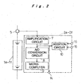
- Fig. 2 is a diagram for use in illustration of how current is detected in the battery ECUs 2a to 2f.
- Each ECU includes an amplification circuit 7, an A/D conversion circuit 8, an external output terminal 14, and an addition circuit 10.
- the amplification circuit 7 processes and amplifies a detection output from a current sensor 5 provided at the charge/discharge circuit at each of the battery pack blocks 1a to 1f.
- the A/D conversion circuit 8 A/D-converts an output from the amplification circuit 7.
- the external output terminal 14 externally outputs an output from the amplification circuit 7.
- the addition circuit 10 adds up the output from the amplification circuit 7 and the input from the external input terminals 15 and 16.
- the digitally converted current data output from the A/D conversion circuit 8 is input to a microcomputer 9, and used for current detection at the battery pack blocks 1a to 1f and calculating the SOC.
- the connection to the external output terminal 14 and the external input terminals 15 and 16 is made as shown in Fig. 1 .
- the external output terminal 14 In the battery ECU 2a in the battery pack system A serving as the master, the external output terminal 14 is in an open state with no connection. Meanwhile among the slave battery pack systems B to F, in the battery pack systems C and E connected in parallel with the battery pack system A, the external input terminals 15 and 16 are in an open state with no connection.
- the external output terminals 14 in the battery pack systems C and E are connected to the external input terminals 15 and 16 in the battery ECU 2a, respectively.
- the battery pack systems A, C, and E and the battery pack systems B, D, and F connected in series with them have common charge/discharge current, and therefore the addition circuit 10 provided at the battery ECUs 2b, 2d, and 2f in the battery pack systems B, D, and F are not used.
- the external output terminals 14 and the external input terminals 15 and 16 are kept open.
- a current value I 2 based on the charge/discharge current detected at the battery pack blocks 1c and 1d by the battery ECU 2c and a current value I 3 based on the charge/discharge current detected at the battery pack blocks 1e and 1f by the battery ECU 2e are input to the external input terminals 15 and 16 in the battery ECU 2a from the external output terminals 14.
- the addition circuit 10 in the battery ECU 2a adds a current value I 1 based on the charge/discharge current detected at the battery pack blocks 1a and 1b output from their respective amplification circuits 7, and the current values I 2 and I 3 .
- the current values I 1 + I 2 + I 3 total charge/discharge current I, and therefore the total charge/discharge current I is obtained without providing an additional current sensor or an associated processing/amplification circuit.
- the battery ECUs 2a to 2f all have the same structure, and the interconnection between them enables the total charge/discharge current I to be calculated by the master battery ECU 2a.
- the battery power source device is formed using a plurality of battery pack systems A to F, a prescribed number of battery pack systems having the same structure as described above need only be prepared and appropriately interconnected.
- the battery ECUs 2a to 2F are compatible, so that the management cost for production management and maintenance service is reduced.
- the total charge/discharge current I produced by the addition circuit 10 in the battery ECU 2a as described above can be output as analog data, while the current may be A/D-converted for input to the microcomputer 9, then used as management data or output to the vehicle ECU as digital data.
- the battery ECUs 2a, 2c, and 2e on the preceding side of the series connection carry out the calculation (addition) for obtaining the total charge/discharge current I, while it is understood that the same result is provided by interconnecting the battery ECUs 2b, 2d, and 2f on the succeeding side for carrying out the addition.
- the total charge/discharge current in the battery power source device having a plurality of battery pack blocks connected in parallel or series-parallel is produced by adding up currents at the charge/discharge circuits at the battery pack blocks connected in parallel.
Landscapes
- Engineering & Computer Science (AREA)
- Power Engineering (AREA)
- Physics & Mathematics (AREA)
- General Physics & Mathematics (AREA)
- Secondary Cells (AREA)
- Electric Propulsion And Braking For Vehicles (AREA)
- Charge And Discharge Circuits For Batteries Or The Like (AREA)
- Tests Of Electric Status Of Batteries (AREA)
Description
- The present invention relates to a battery power source device including a plurality of battery pack blocks, each of which is constituted by connecting a plurality of rechargeable batteries in series, and battery ECUs for controlling the operation state of the battery pack blocks. The plurality of battery pack blocks are connected with one another in parallel or by a combination of serial connection and parallel connection (in series-parallel). The invention also relates to a current detection method therefor.
- A battery power source device applied as a power source for an electric vehicle or hybrid car must supply large electric power. The device is therefore configured as a battery pack system. In the system, a plurality of (six for example) rechargeable batteries are connected together in series to constitute a battery module, and a plurality of (30 for example) such battery modules are connected together in series to constitute a battery pack block. A battery ECU (Electronic Control Unit) is also provided in order to control the operation state of the battery pack block. The battery ECU detects the voltage, current, and temperature of each battery pack block and carry out abnormality detection and various control based on the detection results. To meet a demand for significantly large power for a large-sized vehicle, for example, connecting such battery pack systems together in series, parallel or in series-parallel has been considered.
-
Fig. 3 is a diagram showing the configuration of a battery power source device having six battery pack systems connected together in series-parallel. The battery pack systems all have the same arrangement including abattery pack block 21 and abattery ECU 22. Thebattery pack blocks 21 connected in series-parallel are each connected with a positive electrode charge/discharge terminal 23 and a negative electrode charge/discharge terminal 24. The operation state of each of thebattery pack blocks 21 is monitored and controlled by thecorresponding battery ECU 22. - The
battery pack block 21 is provided with sensors to detect voltage per battery module, charge/discharge current to/from thebattery pack block 21, battery temperature per battery module, and the ambient temperature of thebattery pack block 21, and the detection outputs of the sensors are input to thecorresponding battery ECU 22. Thebattery ECU 22 monitors the operation state or abnormality of thebattery pack block 21 based on the input voltage, current, and temperature detection outputs. Meanwhile, thebattery ECU 22 controls a cooling device such as a blower fan provided at thebattery pack block 21 based on the temperature detection output. Thebattery ECU 22 also calculates SOC (State Of Charge: accumulated electrical quantity relative to battery capacity) based on the voltage, current, and temperature detection outputs. The SOC and the detection output such as voltage are externally output as the operation state data of thebattery pack block 21, so as to be input to a vehicle ECU in a hybrid car for example and used for controlling charge/discharge to/from the battery power source device. - For example in a hybrid car using the battery power source device having a plurality of battery pack blocks connected in series-parallel as described above as the power source, there is a request that the total charge/discharge current I in the battery power source device be known.
- The total charge/discharge current I can be detected by a special current sensor for high current provided at a charge/discharge circuit connected with the positive electrode charge/
discharge terminal 23 or the negative electrode charge/discharge terminal 24 of the battery power source device. However, not only the expensive current sensor is necessary, but also a processing circuit for processing and amplifying the detection output of the current sensor is necessary, which increases the cost. - Meanwhile, the
battery pack blocks 21 are each provided with acurrent sensor 25, and the charge/discharge current is separately detected for eachbattery pack block 21 by thecorresponding battery ECU 22. Consequently, when the charge/discharge current values at thebattery pack blocks 21 connected in parallel are added up, the total charge/discharge current I should be produced. However, the detected current is used to calculate the SOC as described above. Thus, as shown inFig. 4 , once the current is input to thebattery ECU 22, it is amplified by anamplification circuit 16, then A/D-converted by an A/D conversion circuit 17, and input to amicrocomputer 18 for digital processing. The A/D-converted current data cannot be in synchronization with each other among the battery pack systems A1 to A6, and it is therefore impossible to produce the total charge/discharge current I simply by adding them up. -
US 5,504,415 discloses a method and an apparatus for equalizing the state of charge among a plurality of series-connected batteries. A module is connected in parallel with each of the batteries, respectively. Each module contains a voltage divider circuit so that the voltage across a battery may be measured to determine the state of charge, and a circuit which selectively shunts charging current around a battery or applies a discharging current to a battery. A charging transistor applies a charging current to the series of batteries and, depending upon the state of charge of each battery, a portion of the charging current may be shunted around the battery by its associated module so as to prevent overcharging of the battery. A controller monitors the state of charge of each of the batteries and a temperature of each of the batteries and adjusts the portion of the charging shunted around an individual battery so as to rapidly equalize to state of charge among the different batteries. Accordingly, this known arrangement does not detect a total charge/discharge current in a battery power source device including a plurality of battery pack systems connected in parallel or series-parallel. - In
DE 34 31 292 A1 a special kind of a current summing unit in which an output current is the sum of individual currents is shown. However, the input currents do not originate from batteries. Furthermore, the whole arrangement known from this document serves to impress any temperature response to the output current. - A method and apparatus for charging batteries utilizing heterogeneous reaction kinetics is known from
WO 98/44614 - It is an object of the present invention to provide a battery power source device that allows the total charge/discharge current to be obtained using the current detection function provided at each of a plurality of battery pack blocks, and a current detection method therefor.
- In order to achieve the above object, the present invention is directed to a method for detecting a total charge/discharge current in a battery power source device. The battery power source device includes a plurality of battery pack systems connected in parallel. Each of the battery pack systems includes a battery pack block having a plurality of rechargeable batteries connected in series; a battery electronic control unit that detects a current, a voltage, and a temperature and controls an operation state of the battery pack block based on the detection result; and a charge/discharge circuit for connecting the battery pack block. The method for detecting a total charge/discharge current includes detecting currents at the respective charge/discharge circuits of the battery pack systems detected by the corresponding battery electronic control units provided at the battery pack systems connected in parallel; and adding up the currents in an analog data state by an addition unit comprised in the battery electronic control unit.
- According to the current detection method, the total charge/discharge current in the battery power source device is obtained without having to provide current detection means and a processing circuit. Current data after A/D conversion may not accurately be added, while analog data before A/D conversion are accurately added. Consequently, charge/discharge currents detected by the battery ECUs in the battery pack systems connected in parallel can be added up to obtain the total charge/discharge current in the battery power source device.
- An implementation of the invention is directed to a battery power source device, comprising a plurality of battery pack systems connected in parallel. The battery pack systems each includes a battery pack block having a plurality of rechargeable batteries connected in series; a battery electronic control unit for detecting a current, a voltage, and a temperature and for controlling an operation state of the battery pack block based on the detection result; and a charge/discharge circuit for connecting the battery pack block, the charge/discharge circuit including a current sensor. The battery electronic control unit includes an amplification circuit for processing and amplifying a current detection output from the current sensor, and an A/D conversion circuit for receiving and A/D-converting an output value from the amplification circuit for output as a detection value for the current to be used for controlling an operation state of the battery pack system. The power source device further includes an addition unit for adding up the output values of the amplification circuits of the battery electronic control units in the battery pack systems connected in parallel to detect the total charge/discharge current value.
- When the output values in the amplification circuits of the battery electronic control units in the battery pack systems connected in parallel are added up, the total charge/discharge current in the battery power source device is obtained.
- In the above-described configuration, the addition unit collects and adds up the output values of the amplification circuits of the battery electronic control units provided at the battery pack systems connected in parallel. The addition unit is provided as an addition circuit at each of the battery electronic control units , and an arbitrary one of the battery electronic control units serves as a master and the output values of the amplification circuits in the other battery electronic control units serving as slaves are input to the addition circuit in the master battery electronic control unit for addition. Thereby, all the battery electronic control units can have the same arrangement. In this way, the production management is efficient and the output values are collected to the addition unit in the master battery electronic control unit by the interconnection.
- The master battery electronic control unit A/D-converts the total charge/discharge current value produced by the addition by the addition circuit to be used as management data for the operation state. The total charge/discharge current data can be provided to equipment that uses the battery power source device.
- Preferred embodiments of the present invention will be hereinafter described with reference to the accompanying drawings, in which:
-
Fig. 1 is a block diagram showing the configuration of a battery power source device according to an embodiment of the invention; -
Fig. 2 is a block diagram for use in illustration of how current is detected by the battery ECU according to the embodiment; -
Fig. 3 is a block diagram showing the configuration of a conventional battery power source device; and -
Fig. 4 is a block diagram for use in illustration of how current is detected by the conventional battery electronic control unit. - In the embodiment, a battery power source device is applied to a hybrid car, particularly to a large-sized hybrid car using both a motor and an engine. As shown in
Fig. 1 , in the battery power source device according to the embodiment, battery pack blocks 1a and 1b, 1c and 1d, and 1e and 1f are connected in series, and then the three sets of the series connections are connected in parallel, in other words, the battery pack blocks are connected in series-parallel. In this way, large output voltage and large output current are supplied. - The battery pack blocks 1a to 1f each include 40 battery modules connected in series. The battery modules each include six nickel-metal hydride rechargeable batteries connected in series. The battery pack blocks 1a to 1f each include detectors such as a current sensor, a voltage sensor and a temperature sensor and a cooling fan for cooling the batteries. The battery pack blocks 1a to 1f are connected with
battery ECUs 2a to 2f, respectively and in this way, battery pack systems A to F are formed. The battery pack systems A to F all have the same structure, while the interconnection between them is provided so that the battery pack system A serves as a master and the other battery pack systems B to F serve as slaves. - The charge/discharge current and voltage at the battery pack blocks 1a to 1f, voltage and temperature on a battery module basis, and the air temperature (ambient temperature) for cooling the battery pack blocks 1a to 1f are detected by the current sensor, the voltage sensor, and the temperature sensor. In the battery pack systems A to F, the
battery ECUs 2a to 2f monitor the operation state of the battery pack blocks 1a to 1f based on these detection outputs. Thebattery ECUs 2a to 2f control the rotation of the cooling fans, also calculate the SOC, and request the vehicle ECU, the control device of the vehicle to provide charge/discharge to keep the SOC appropriate. The voltage, current, and temperature data and the resultant SOC are output to the vehicle ECU as operation state information. -
Fig. 2 is a diagram for use in illustration of how current is detected in thebattery ECUs 2a to 2f. Each ECU includes an amplification circuit 7, an A/D conversion circuit 8, anexternal output terminal 14, and anaddition circuit 10. The amplification circuit 7 processes and amplifies a detection output from acurrent sensor 5 provided at the charge/discharge circuit at each of the battery pack blocks 1a to 1f. The A/D conversion circuit 8 A/D-converts an output from the amplification circuit 7. Theexternal output terminal 14 externally outputs an output from the amplification circuit 7. Theaddition circuit 10 adds up the output from the amplification circuit 7 and the input from theexternal input terminals D conversion circuit 8 is input to amicrocomputer 9, and used for current detection at the battery pack blocks 1a to 1f and calculating the SOC. - The connection to the
external output terminal 14 and theexternal input terminals Fig. 1 . In thebattery ECU 2a in the battery pack system A serving as the master, theexternal output terminal 14 is in an open state with no connection. Meanwhile among the slave battery pack systems B to F, in the battery pack systems C and E connected in parallel with the battery pack system A, theexternal input terminals external output terminals 14 in the battery pack systems C and E are connected to theexternal input terminals battery ECU 2a, respectively. The battery pack systems A, C, and E and the battery pack systems B, D, and F connected in series with them have common charge/discharge current, and therefore theaddition circuit 10 provided at thebattery ECUs external output terminals 14 and theexternal input terminals - By this connection arrangement, a current value I2 based on the charge/discharge current detected at the battery pack blocks 1c and 1d by the
battery ECU 2c and a current value I3 based on the charge/discharge current detected at thebattery pack blocks 1e and 1f by thebattery ECU 2e are input to theexternal input terminals battery ECU 2a from theexternal output terminals 14. Theaddition circuit 10 in thebattery ECU 2a adds a current value I1 based on the charge/discharge current detected at the battery pack blocks 1a and 1b output from their respective amplification circuits 7, and the current values I2 and I3. The current values I1 + I2 + I3 = total charge/discharge current I, and therefore the total charge/discharge current I is obtained without providing an additional current sensor or an associated processing/amplification circuit. - The
battery ECUs 2a to 2f all have the same structure, and the interconnection between them enables the total charge/discharge current I to be calculated by themaster battery ECU 2a. Thus, when the battery power source device is formed using a plurality of battery pack systems A to F, a prescribed number of battery pack systems having the same structure as described above need only be prepared and appropriately interconnected. Thebattery ECUs 2a to 2F are compatible, so that the management cost for production management and maintenance service is reduced. - The total charge/discharge current I produced by the
addition circuit 10 in thebattery ECU 2a as described above can be output as analog data, while the current may be A/D-converted for input to themicrocomputer 9, then used as management data or output to the vehicle ECU as digital data. - In the above description, the
battery ECUs battery ECUs - As in the foregoing, according to the invention, without having to provide current detection means, the total charge/discharge current in the battery power source device having a plurality of battery pack blocks connected in parallel or series-parallel is produced by adding up currents at the charge/discharge circuits at the battery pack blocks connected in parallel.
Claims (4)
- A method for detecting a total charge/discharge current in a battery power source device, said battery power source device including a plurality of battery pack systems (A, B, C, D, E, F) connected in parallel
said battery pack systems (A, B, C, D, E, F) each including a battery pack block (1a, 1b, 1c, 1d, 1e, 1f) having a plurality of rechargeable batteries connected in series, a battery electronic control unit (2a, 2b, 2c, 2d, 2e, 2f) for detecting a current, a voltage, and a temperature and for controlling an operation state of the battery pack block based on the detection result, and a charge/discharge circuit for connecting the battery pack block (1a, 1b, 1c, 1d, 1e, 1f),
the method comprising detecting currents at the respective charge/discharge circuits of the battery pack systems (A, B, C, D, E, F) detected by said corresponding battery electronic control units (2a, 2b, 2c, 2d, 2e, 2f) provided at the battery pack system connected in parallel,
characterized in that the currents are added up in an analog data state by an addition unit (10) comprised in the battery electronic control unit to detect the total charge/discharge current. - A battery power source device, comprising a plurality of battery pack systems (A, B, C, D, E, F) connected in parallel,
said battery pack systems (A, B, C, D, E, F) each including:a battery pack block (1a, 1b, 1c, 1d, 1e, 1f) having a plurality of rechargeable batteries connected in series,a battery electronic control unit (2a, 2b, 2c, 2d, 2e, 2f) for detecting a current, a voltage, and a temperature and for controlling an operation state of the battery pack block based on the detection result, anda charge/discharge circuit for connecting the battery pack block, the charge/discharge circuit including a current sensor (5),said battery electronic control unit including an amplification circuit (7) for processing and amplifying a current detection output from the current sensor (5), and an A/D conversion circuit (8) for receiving and A/D-converting an output value from the amplification circuit (7) for output as a detection value for said current to be used for controlling an operation state of the battery pack system,characterized in that said battery electronic control unit further comprises an addition unit (10) for collecting and adding up the output values of said amplification circuits (7) of the battery ECUs (2a, 2b, 2c, 2d, 2e, 2f) in the battery pack systems (A, B, C, D, E, F) connected in parallel to detect the total charge/discharge current value. - The battery power source device according to claim 2,
wherein
the addition unit (10) is an addition circuit provided at each of said battery electronic control units (2a, 2b, 2c, 2d, 2e, 2f), and an arbitrary one of the battery electronic control units (2a, 2b, 2c, 2d, 2e, 2f) serves as a master and the output values of the amplification circuits (7) in the other battery electronic control units (2a, 2b, 2c, 2d, 2e, 2f) serving as slaves are input to the addition circuit in the master battery electronic control unit for addition. - The battery power source device according to claim 3,
wherein
the master battery electronic control unit A/D-converts the total charge/discharge current value produced by the addition by the addition circuit to be used as management data for the operation state.
Applications Claiming Priority (2)
| Application Number | Priority Date | Filing Date | Title |
|---|---|---|---|
| JP2001365941 | 2001-11-30 | ||
| JP2001365941A JP3936179B2 (en) | 2001-11-30 | 2001-11-30 | Battery power supply device and current detection method thereof |
Publications (3)
| Publication Number | Publication Date |
|---|---|
| EP1317045A2 EP1317045A2 (en) | 2003-06-04 |
| EP1317045A3 EP1317045A3 (en) | 2004-06-23 |
| EP1317045B1 true EP1317045B1 (en) | 2009-10-07 |
Family
ID=19175911
Family Applications (1)
| Application Number | Title | Priority Date | Filing Date |
|---|---|---|---|
| EP02258186A Expired - Lifetime EP1317045B1 (en) | 2001-11-30 | 2002-11-27 | Battery power source device and current detection method therefor |
Country Status (4)
| Country | Link |
|---|---|
| US (1) | US6762590B2 (en) |
| EP (1) | EP1317045B1 (en) |
| JP (1) | JP3936179B2 (en) |
| DE (1) | DE60233922D1 (en) |
Families Citing this family (34)
| Publication number | Priority date | Publication date | Assignee | Title |
|---|---|---|---|---|
| JP3939546B2 (en) * | 2001-12-06 | 2007-07-04 | パナソニック・イーブイ・エナジー株式会社 | Battery power device for electric vehicle |
| JP3893291B2 (en) * | 2002-01-10 | 2007-03-14 | パナソニック・イーブイ・エナジー株式会社 | Battery power unit for hybrid vehicles |
| JP4165334B2 (en) * | 2003-08-07 | 2008-10-15 | トヨタ自動車株式会社 | Control device for cooling fan |
| DE102005020835A1 (en) * | 2004-05-13 | 2006-03-09 | Robert Bosch Gmbh | Battery state detection |
| US20060103348A1 (en) * | 2004-11-15 | 2006-05-18 | Melichar Robert J | Maximum and minimum power limit calculator for parallel battery subpacks |
| JP4313754B2 (en) | 2004-12-10 | 2009-08-12 | 住友電装株式会社 | Communication control device |
| KR100766268B1 (en) * | 2005-02-14 | 2007-10-15 | 주식회사 엘지화학 | Automatic air conditioning filter management device for battery pack and its automatic management method |
| KR100681769B1 (en) * | 2005-07-01 | 2007-02-15 | 한국과학기술연구원 | Multi Channel Electronic Load Unit |
| US7446504B2 (en) * | 2005-11-10 | 2008-11-04 | Lg Chem, Ltd. | System, method, and article of manufacture for determining an estimated battery state vector |
| US7723957B2 (en) * | 2005-11-30 | 2010-05-25 | Lg Chem, Ltd. | System, method, and article of manufacture for determining an estimated battery parameter vector |
| JP5170610B2 (en) * | 2006-02-28 | 2013-03-27 | 日立工機株式会社 | Charger |
| US7489106B1 (en) * | 2006-03-31 | 2009-02-10 | Victor Tikhonov | Battery optimization system and method of use |
| ITMI20061295A1 (en) | 2006-07-04 | 2008-01-05 | Campagnolo Srl | MEDOTO AND ELECTRICAL ENERGY DELIVERY SYSTEM FROM A BATTERY POWER UNIT |
| ITMI20061296A1 (en) | 2006-07-04 | 2008-01-05 | Campagnolo Srl | METHOD OF CONTROL AND SYSTEM OF CHARGING A BATTERY POWER UNIT |
| FR2912265B1 (en) * | 2007-02-06 | 2009-04-24 | Batscap Sa | BATTERY WITH SERIES CELL MODULES, AND VEHICLE EQUIPPED WITH SAME |
| US8005632B2 (en) * | 2007-11-07 | 2011-08-23 | GM Global Technology Operations LLC | Method and apparatus for detecting faults in a current sensing device |
| WO2009103079A2 (en) * | 2008-02-15 | 2009-08-20 | Atieva, Inc. | Method of electrically connecting cell terminals in a battery pack |
| US20090206841A1 (en) * | 2008-02-15 | 2009-08-20 | Sam Weng | Intelligent fault-tolerant battery management system |
| JP2010104179A (en) * | 2008-10-24 | 2010-05-06 | Sanyo Electric Co Ltd | Power supply device and electric vehicle |
| KR101016813B1 (en) * | 2009-05-19 | 2011-02-21 | 에스비리모티브 주식회사 | Battery Management System and Its Driving Method |
| US8207740B2 (en) * | 2009-06-23 | 2012-06-26 | GM Global Technology Operations LLC | Method for use with a vehicle battery pack having a number of individual battery cells |
| JP4823345B2 (en) * | 2009-09-18 | 2011-11-24 | 三菱重工業株式会社 | Battery system |
| US8872518B2 (en) | 2010-06-25 | 2014-10-28 | Atieva, Inc. | Determining the state of-charge of batteries via selective sampling of extrapolated open circuit voltage |
| US8449998B2 (en) | 2011-04-25 | 2013-05-28 | Lg Chem, Ltd. | Battery system and method for increasing an operational life of a battery cell |
| US20150180260A1 (en) * | 2013-12-20 | 2015-06-25 | Metal Industries Research & Development Centre | Power supply with current sharing control and the battery module |
| US20170190257A1 (en) * | 2015-12-30 | 2017-07-06 | Thunder Power Hong Kong Ltd. | Smart charging system for electric vehicle battery packs |
| WO2020170027A1 (en) * | 2019-02-20 | 2020-08-27 | Goryunov Vladimir N | Apparatus and method for monitoring and compensating for block rechargeable batteries |
| RU2697185C1 (en) * | 2019-02-20 | 2019-08-13 | Владимир Николаевич Горюнов | Method for automatic monitoring and equalization of charging degree of parallel-serial connection of accumulators of unit |
| CN110441703A (en) * | 2019-09-07 | 2019-11-12 | 深圳市凯德旺科技有限公司 | A kind of evaluation method and its detection system of the lithium battery SOC of mobile charging system |
| DE102019220475A1 (en) * | 2019-12-20 | 2021-06-24 | Robert Bosch Gmbh | Electrical processing device with a power supply device |
| KR102789141B1 (en) * | 2020-02-17 | 2025-03-28 | 주식회사 엘지에너지솔루션 | Battery apparatus and current sensor diagnosis method |
| CN117837045A (en) * | 2021-12-29 | 2024-04-05 | 宁德时代新能源科技股份有限公司 | A method for regulating overcurrent of energy storage system and energy storage system |
| CN119731903A (en) | 2022-08-16 | 2025-03-28 | V·戈尔朱诺夫 | Apparatus and method for monitoring and equalizing charge level in a battery |
| KR102888815B1 (en) * | 2024-10-28 | 2025-11-21 | (주) 코아네트 | Storage battery monitoring system for the power supply of the DAS communication modem |
Family Cites Families (12)
| Publication number | Priority date | Publication date | Assignee | Title |
|---|---|---|---|---|
| DE3431292A1 (en) * | 1984-08-25 | 1986-03-06 | Robert Bosch Gmbh, 7000 Stuttgart | Circuit arrangement for generating a current |
| US5311112A (en) * | 1993-02-26 | 1994-05-10 | Kussmaul Electronics Company Inc. | Automatic battery charging system |
| US5504415A (en) * | 1993-12-03 | 1996-04-02 | Electronic Power Technology, Inc. | Method and apparatus for automatic equalization of series-connected batteries |
| FR2742601B1 (en) * | 1995-12-15 | 1998-01-09 | Renault | ACCUMULATOR BATTERY MANAGEMENT SYSTEM |
| US6495992B1 (en) * | 1996-03-26 | 2002-12-17 | Norvik Traction Inc. | Method and apparatus for charging batteries utilizing heterogeneous reaction kinetics |
| JP3543579B2 (en) * | 1997-10-29 | 2004-07-14 | 新神戸電機株式会社 | Method and apparatus for detecting charge / discharge current of secondary battery |
| US6420852B1 (en) * | 1998-08-21 | 2002-07-16 | Sony Corporation | Battery pack |
| JP2001185228A (en) * | 1999-12-24 | 2001-07-06 | Sanyo Electric Co Ltd | Electric power supply equipped with battery |
| JP3743704B2 (en) * | 2000-09-25 | 2006-02-08 | Necトーキン栃木株式会社 | Battery pack |
| US7400113B2 (en) * | 2001-03-30 | 2008-07-15 | Designline International Holdings, Llc | Battery management unit, system and method |
| JP4786058B2 (en) * | 2001-05-01 | 2011-10-05 | 本田技研工業株式会社 | Power storage device remaining capacity detection device |
| JP2003004822A (en) * | 2001-06-15 | 2003-01-08 | Matsushita Electric Ind Co Ltd | Battery power unit |
-
2001
- 2001-11-30 JP JP2001365941A patent/JP3936179B2/en not_active Expired - Fee Related
-
2002
- 2002-11-26 US US10/303,894 patent/US6762590B2/en not_active Expired - Fee Related
- 2002-11-27 DE DE60233922T patent/DE60233922D1/en not_active Expired - Lifetime
- 2002-11-27 EP EP02258186A patent/EP1317045B1/en not_active Expired - Lifetime
Also Published As
| Publication number | Publication date |
|---|---|
| EP1317045A2 (en) | 2003-06-04 |
| JP3936179B2 (en) | 2007-06-27 |
| US20030102871A1 (en) | 2003-06-05 |
| JP2003168488A (en) | 2003-06-13 |
| DE60233922D1 (en) | 2009-11-19 |
| US6762590B2 (en) | 2004-07-13 |
| EP1317045A3 (en) | 2004-06-23 |
Similar Documents
| Publication | Publication Date | Title |
|---|---|---|
| US6762590B2 (en) | Battery power source device and current detection method therefor | |
| US10008862B2 (en) | Power storage device, power storage system, and control method of power storage device | |
| KR102555753B1 (en) | Charging station for charging electric vehicles | |
| US9966759B2 (en) | Battery monitor circuit, storage apparatus, electronic apparatus, electric-powered vehicle, and power system | |
| CN103250300B (en) | Battery system and method for determining battery module voltage | |
| US9270135B2 (en) | Power supply apparatus and power supply switching method | |
| US10587127B2 (en) | Charging device, charging control method, electricity storage device, power storage device, power system, and electric vehicle | |
| US10069311B2 (en) | Power storage device and method of controlling power storage device | |
| EP1014533A3 (en) | A battery charge management architecture | |
| EP2594949A1 (en) | Power supply device | |
| JPH08140272A (en) | Battery status management system | |
| US20200212507A1 (en) | Electricity storage system and management device | |
| JPWO2012131797A1 (en) | Master device, slave device, communication system, battery system, electric vehicle, moving object, power storage device, and power supply device | |
| CA2642527A1 (en) | Scalable intelligent power supply system and method | |
| JP6253800B2 (en) | In-vehicle DCDC converter | |
| GB2312571A (en) | Charging series connected batteries | |
| US11411259B2 (en) | Battery control unit | |
| WO2018066323A1 (en) | Vehicle battery monitoring device and vehicle battery monitoring system | |
| WO2012026093A1 (en) | Battery module, battery system, electric vehicle, mobile body, electric power storage device, and electric power supply device | |
| EP2579047A1 (en) | Voltage measuring apparatus for battery pack | |
| KR102781324B1 (en) | Device and method for diagnosing condition of removed battery pack | |
| US12261271B2 (en) | Management device and power storage system | |
| JP2002008734A (en) | Battery voltage detecting method and battery voltage detecting device | |
| JP4653062B2 (en) | Voltage measuring device and electric vehicle | |
| JP7606492B2 (en) | Battery control device and battery connection control device |
Legal Events
| Date | Code | Title | Description |
|---|---|---|---|
| PUAI | Public reference made under article 153(3) epc to a published international application that has entered the european phase |
Free format text: ORIGINAL CODE: 0009012 |
|
| AK | Designated contracting states |
Designated state(s): AT BE BG CH CY CZ DE DK EE ES FI FR GB GR IE IT LI LU MC NL PT SE SK TR |
|
| AX | Request for extension of the european patent |
Extension state: AL LT LV MK RO SI |
|
| PUAL | Search report despatched |
Free format text: ORIGINAL CODE: 0009013 |
|
| AK | Designated contracting states |
Kind code of ref document: A3 Designated state(s): AT BE BG CH CY CZ DE DK EE ES FI FR GB GR IE IT LI LU MC NL PT SE SK TR |
|
| AX | Request for extension of the european patent |
Extension state: AL LT LV MK RO SI |
|
| RIC1 | Information provided on ipc code assigned before grant |
Ipc: 7H 02J 7/00 B Ipc: 7G 01R 19/165 A |
|
| 17P | Request for examination filed |
Effective date: 20041209 |
|
| AKX | Designation fees paid |
Designated state(s): DE FR GB |
|
| 17Q | First examination report despatched |
Effective date: 20071106 |
|
| GRAP | Despatch of communication of intention to grant a patent |
Free format text: ORIGINAL CODE: EPIDOSNIGR1 |
|
| GRAS | Grant fee paid |
Free format text: ORIGINAL CODE: EPIDOSNIGR3 |
|
| GRAA | (expected) grant |
Free format text: ORIGINAL CODE: 0009210 |
|
| AK | Designated contracting states |
Kind code of ref document: B1 Designated state(s): DE FR GB |
|
| REG | Reference to a national code |
Ref country code: GB Ref legal event code: FG4D |
|
| REF | Corresponds to: |
Ref document number: 60233922 Country of ref document: DE Date of ref document: 20091119 Kind code of ref document: P |
|
| PLBE | No opposition filed within time limit |
Free format text: ORIGINAL CODE: 0009261 |
|
| STAA | Information on the status of an ep patent application or granted ep patent |
Free format text: STATUS: NO OPPOSITION FILED WITHIN TIME LIMIT |
|
| 26N | No opposition filed |
Effective date: 20100708 |
|
| PGFP | Annual fee paid to national office [announced via postgrant information from national office to epo] |
Ref country code: GB Payment date: 20101123 Year of fee payment: 9 |
|
| GBPC | Gb: european patent ceased through non-payment of renewal fee |
Effective date: 20111127 |
|
| PG25 | Lapsed in a contracting state [announced via postgrant information from national office to epo] |
Ref country code: GB Free format text: LAPSE BECAUSE OF NON-PAYMENT OF DUE FEES Effective date: 20111127 |
|
| PGFP | Annual fee paid to national office [announced via postgrant information from national office to epo] |
Ref country code: DE Payment date: 20121123 Year of fee payment: 11 |
|
| PGFP | Annual fee paid to national office [announced via postgrant information from national office to epo] |
Ref country code: FR Payment date: 20121217 Year of fee payment: 11 |
|
| REG | Reference to a national code |
Ref country code: FR Ref legal event code: ST Effective date: 20140731 |
|
| PG25 | Lapsed in a contracting state [announced via postgrant information from national office to epo] |
Ref country code: DE Free format text: LAPSE BECAUSE OF NON-PAYMENT OF DUE FEES Effective date: 20140603 |
|
| REG | Reference to a national code |
Ref country code: DE Ref legal event code: R119 Ref document number: 60233922 Country of ref document: DE Effective date: 20140603 |
|
| PG25 | Lapsed in a contracting state [announced via postgrant information from national office to epo] |
Ref country code: FR Free format text: LAPSE BECAUSE OF NON-PAYMENT OF DUE FEES Effective date: 20131202 |