EP1316767A1 - Verfahren und Vorrichtung zur Erzeugung von flüssigem Sauerstoff und flüssigem Stickstoff - Google Patents
Verfahren und Vorrichtung zur Erzeugung von flüssigem Sauerstoff und flüssigem Stickstoff Download PDFInfo
- Publication number
- EP1316767A1 EP1316767A1 EP02024689A EP02024689A EP1316767A1 EP 1316767 A1 EP1316767 A1 EP 1316767A1 EP 02024689 A EP02024689 A EP 02024689A EP 02024689 A EP02024689 A EP 02024689A EP 1316767 A1 EP1316767 A1 EP 1316767A1
- Authority
- EP
- European Patent Office
- Prior art keywords
- heat exchanger
- nitrogen
- oxygen
- gas
- liquefied
- Prior art date
- Legal status (The legal status is an assumption and is not a legal conclusion. Google has not performed a legal analysis and makes no representation as to the accuracy of the status listed.)
- Withdrawn
Links
- IJGRMHOSHXDMSA-UHFFFAOYSA-N Atomic nitrogen Chemical compound N#N IJGRMHOSHXDMSA-UHFFFAOYSA-N 0.000 title claims abstract description 55
- 229910052757 nitrogen Inorganic materials 0.000 title claims abstract description 26
- 238000000034 method Methods 0.000 title claims abstract description 16
- 239000007788 liquid Substances 0.000 title claims description 15
- MYMOFIZGZYHOMD-UHFFFAOYSA-N Dioxygen Chemical compound O=O MYMOFIZGZYHOMD-UHFFFAOYSA-N 0.000 title claims description 13
- 239000007789 gas Substances 0.000 claims abstract description 24
- XKRFYHLGVUSROY-UHFFFAOYSA-N Argon Chemical compound [Ar] XKRFYHLGVUSROY-UHFFFAOYSA-N 0.000 claims abstract description 18
- QVGXLLKOCUKJST-UHFFFAOYSA-N atomic oxygen Chemical compound [O] QVGXLLKOCUKJST-UHFFFAOYSA-N 0.000 claims abstract description 14
- 239000001301 oxygen Substances 0.000 claims abstract description 14
- 229910052760 oxygen Inorganic materials 0.000 claims abstract description 14
- 229910052786 argon Inorganic materials 0.000 claims abstract description 9
- 238000000926 separation method Methods 0.000 claims description 10
- 238000005057 refrigeration Methods 0.000 claims description 7
- 230000006835 compression Effects 0.000 claims description 2
- 238000007906 compression Methods 0.000 claims description 2
- 229910001873 dinitrogen Inorganic materials 0.000 claims 3
- 229910001882 dioxygen Inorganic materials 0.000 claims 3
- 238000010438 heat treatment Methods 0.000 claims 1
- 239000012530 fluid Substances 0.000 abstract description 3
- 238000004821 distillation Methods 0.000 abstract 1
- 239000000203 mixture Substances 0.000 description 3
- 238000005265 energy consumption Methods 0.000 description 2
- 239000012263 liquid product Substances 0.000 description 2
- 238000004519 manufacturing process Methods 0.000 description 2
- 238000009833 condensation Methods 0.000 description 1
- 230000005494 condensation Effects 0.000 description 1
- 238000011010 flushing procedure Methods 0.000 description 1
- 238000005191 phase separation Methods 0.000 description 1
Images
Classifications
-
- F—MECHANICAL ENGINEERING; LIGHTING; HEATING; WEAPONS; BLASTING
- F25—REFRIGERATION OR COOLING; COMBINED HEATING AND REFRIGERATION SYSTEMS; HEAT PUMP SYSTEMS; MANUFACTURE OR STORAGE OF ICE; LIQUEFACTION SOLIDIFICATION OF GASES
- F25J—LIQUEFACTION, SOLIDIFICATION OR SEPARATION OF GASES OR GASEOUS OR LIQUEFIED GASEOUS MIXTURES BY PRESSURE AND COLD TREATMENT OR BY BRINGING THEM INTO THE SUPERCRITICAL STATE
- F25J1/00—Processes or apparatus for liquefying or solidifying gases or gaseous mixtures
- F25J1/02—Processes or apparatus for liquefying or solidifying gases or gaseous mixtures requiring the use of refrigeration, e.g. of helium or hydrogen ; Details and kind of the refrigeration system used; Integration with other units or processes; Controlling aspects of the process
- F25J1/0211—Processes or apparatus for liquefying or solidifying gases or gaseous mixtures requiring the use of refrigeration, e.g. of helium or hydrogen ; Details and kind of the refrigeration system used; Integration with other units or processes; Controlling aspects of the process using a multi-component refrigerant [MCR] fluid in a closed vapor compression cycle
- F25J1/0212—Processes or apparatus for liquefying or solidifying gases or gaseous mixtures requiring the use of refrigeration, e.g. of helium or hydrogen ; Details and kind of the refrigeration system used; Integration with other units or processes; Controlling aspects of the process using a multi-component refrigerant [MCR] fluid in a closed vapor compression cycle as a single flow MCR cycle
-
- F—MECHANICAL ENGINEERING; LIGHTING; HEATING; WEAPONS; BLASTING
- F25—REFRIGERATION OR COOLING; COMBINED HEATING AND REFRIGERATION SYSTEMS; HEAT PUMP SYSTEMS; MANUFACTURE OR STORAGE OF ICE; LIQUEFACTION SOLIDIFICATION OF GASES
- F25J—LIQUEFACTION, SOLIDIFICATION OR SEPARATION OF GASES OR GASEOUS OR LIQUEFIED GASEOUS MIXTURES BY PRESSURE AND COLD TREATMENT OR BY BRINGING THEM INTO THE SUPERCRITICAL STATE
- F25J1/00—Processes or apparatus for liquefying or solidifying gases or gaseous mixtures
- F25J1/0002—Processes or apparatus for liquefying or solidifying gases or gaseous mixtures characterised by the fluid to be liquefied
- F25J1/0012—Primary atmospheric gases, e.g. air
- F25J1/0015—Nitrogen
-
- F—MECHANICAL ENGINEERING; LIGHTING; HEATING; WEAPONS; BLASTING
- F25—REFRIGERATION OR COOLING; COMBINED HEATING AND REFRIGERATION SYSTEMS; HEAT PUMP SYSTEMS; MANUFACTURE OR STORAGE OF ICE; LIQUEFACTION SOLIDIFICATION OF GASES
- F25J—LIQUEFACTION, SOLIDIFICATION OR SEPARATION OF GASES OR GASEOUS OR LIQUEFIED GASEOUS MIXTURES BY PRESSURE AND COLD TREATMENT OR BY BRINGING THEM INTO THE SUPERCRITICAL STATE
- F25J1/00—Processes or apparatus for liquefying or solidifying gases or gaseous mixtures
- F25J1/0002—Processes or apparatus for liquefying or solidifying gases or gaseous mixtures characterised by the fluid to be liquefied
- F25J1/0012—Primary atmospheric gases, e.g. air
- F25J1/0017—Oxygen
-
- F—MECHANICAL ENGINEERING; LIGHTING; HEATING; WEAPONS; BLASTING
- F25—REFRIGERATION OR COOLING; COMBINED HEATING AND REFRIGERATION SYSTEMS; HEAT PUMP SYSTEMS; MANUFACTURE OR STORAGE OF ICE; LIQUEFACTION SOLIDIFICATION OF GASES
- F25J—LIQUEFACTION, SOLIDIFICATION OR SEPARATION OF GASES OR GASEOUS OR LIQUEFIED GASEOUS MIXTURES BY PRESSURE AND COLD TREATMENT OR BY BRINGING THEM INTO THE SUPERCRITICAL STATE
- F25J1/00—Processes or apparatus for liquefying or solidifying gases or gaseous mixtures
- F25J1/003—Processes or apparatus for liquefying or solidifying gases or gaseous mixtures characterised by the kind of cold generation within the liquefaction unit for compensating heat leaks and liquid production
- F25J1/0047—Processes or apparatus for liquefying or solidifying gases or gaseous mixtures characterised by the kind of cold generation within the liquefaction unit for compensating heat leaks and liquid production using an "external" refrigerant stream in a closed vapor compression cycle
- F25J1/005—Processes or apparatus for liquefying or solidifying gases or gaseous mixtures characterised by the kind of cold generation within the liquefaction unit for compensating heat leaks and liquid production using an "external" refrigerant stream in a closed vapor compression cycle by expansion of a gaseous refrigerant stream with extraction of work
-
- F—MECHANICAL ENGINEERING; LIGHTING; HEATING; WEAPONS; BLASTING
- F25—REFRIGERATION OR COOLING; COMBINED HEATING AND REFRIGERATION SYSTEMS; HEAT PUMP SYSTEMS; MANUFACTURE OR STORAGE OF ICE; LIQUEFACTION SOLIDIFICATION OF GASES
- F25J—LIQUEFACTION, SOLIDIFICATION OR SEPARATION OF GASES OR GASEOUS OR LIQUEFIED GASEOUS MIXTURES BY PRESSURE AND COLD TREATMENT OR BY BRINGING THEM INTO THE SUPERCRITICAL STATE
- F25J1/00—Processes or apparatus for liquefying or solidifying gases or gaseous mixtures
- F25J1/003—Processes or apparatus for liquefying or solidifying gases or gaseous mixtures characterised by the kind of cold generation within the liquefaction unit for compensating heat leaks and liquid production
- F25J1/0047—Processes or apparatus for liquefying or solidifying gases or gaseous mixtures characterised by the kind of cold generation within the liquefaction unit for compensating heat leaks and liquid production using an "external" refrigerant stream in a closed vapor compression cycle
- F25J1/0052—Processes or apparatus for liquefying or solidifying gases or gaseous mixtures characterised by the kind of cold generation within the liquefaction unit for compensating heat leaks and liquid production using an "external" refrigerant stream in a closed vapor compression cycle by vaporising a liquid refrigerant stream
- F25J1/0055—Processes or apparatus for liquefying or solidifying gases or gaseous mixtures characterised by the kind of cold generation within the liquefaction unit for compensating heat leaks and liquid production using an "external" refrigerant stream in a closed vapor compression cycle by vaporising a liquid refrigerant stream originating from an incorporated cascade
-
- F—MECHANICAL ENGINEERING; LIGHTING; HEATING; WEAPONS; BLASTING
- F25—REFRIGERATION OR COOLING; COMBINED HEATING AND REFRIGERATION SYSTEMS; HEAT PUMP SYSTEMS; MANUFACTURE OR STORAGE OF ICE; LIQUEFACTION SOLIDIFICATION OF GASES
- F25J—LIQUEFACTION, SOLIDIFICATION OR SEPARATION OF GASES OR GASEOUS OR LIQUEFIED GASEOUS MIXTURES BY PRESSURE AND COLD TREATMENT OR BY BRINGING THEM INTO THE SUPERCRITICAL STATE
- F25J1/00—Processes or apparatus for liquefying or solidifying gases or gaseous mixtures
- F25J1/006—Processes or apparatus for liquefying or solidifying gases or gaseous mixtures characterised by the refrigerant fluid used
- F25J1/007—Primary atmospheric gases, mixtures thereof
-
- F—MECHANICAL ENGINEERING; LIGHTING; HEATING; WEAPONS; BLASTING
- F25—REFRIGERATION OR COOLING; COMBINED HEATING AND REFRIGERATION SYSTEMS; HEAT PUMP SYSTEMS; MANUFACTURE OR STORAGE OF ICE; LIQUEFACTION SOLIDIFICATION OF GASES
- F25J—LIQUEFACTION, SOLIDIFICATION OR SEPARATION OF GASES OR GASEOUS OR LIQUEFIED GASEOUS MIXTURES BY PRESSURE AND COLD TREATMENT OR BY BRINGING THEM INTO THE SUPERCRITICAL STATE
- F25J1/00—Processes or apparatus for liquefying or solidifying gases or gaseous mixtures
- F25J1/006—Processes or apparatus for liquefying or solidifying gases or gaseous mixtures characterised by the refrigerant fluid used
- F25J1/007—Primary atmospheric gases, mixtures thereof
- F25J1/0072—Nitrogen
-
- F—MECHANICAL ENGINEERING; LIGHTING; HEATING; WEAPONS; BLASTING
- F25—REFRIGERATION OR COOLING; COMBINED HEATING AND REFRIGERATION SYSTEMS; HEAT PUMP SYSTEMS; MANUFACTURE OR STORAGE OF ICE; LIQUEFACTION SOLIDIFICATION OF GASES
- F25J—LIQUEFACTION, SOLIDIFICATION OR SEPARATION OF GASES OR GASEOUS OR LIQUEFIED GASEOUS MIXTURES BY PRESSURE AND COLD TREATMENT OR BY BRINGING THEM INTO THE SUPERCRITICAL STATE
- F25J1/00—Processes or apparatus for liquefying or solidifying gases or gaseous mixtures
- F25J1/006—Processes or apparatus for liquefying or solidifying gases or gaseous mixtures characterised by the refrigerant fluid used
- F25J1/007—Primary atmospheric gases, mixtures thereof
- F25J1/0075—Oxygen
-
- F—MECHANICAL ENGINEERING; LIGHTING; HEATING; WEAPONS; BLASTING
- F25—REFRIGERATION OR COOLING; COMBINED HEATING AND REFRIGERATION SYSTEMS; HEAT PUMP SYSTEMS; MANUFACTURE OR STORAGE OF ICE; LIQUEFACTION SOLIDIFICATION OF GASES
- F25J—LIQUEFACTION, SOLIDIFICATION OR SEPARATION OF GASES OR GASEOUS OR LIQUEFIED GASEOUS MIXTURES BY PRESSURE AND COLD TREATMENT OR BY BRINGING THEM INTO THE SUPERCRITICAL STATE
- F25J1/00—Processes or apparatus for liquefying or solidifying gases or gaseous mixtures
- F25J1/006—Processes or apparatus for liquefying or solidifying gases or gaseous mixtures characterised by the refrigerant fluid used
- F25J1/007—Primary atmospheric gases, mixtures thereof
- F25J1/0077—Argon
-
- F—MECHANICAL ENGINEERING; LIGHTING; HEATING; WEAPONS; BLASTING
- F25—REFRIGERATION OR COOLING; COMBINED HEATING AND REFRIGERATION SYSTEMS; HEAT PUMP SYSTEMS; MANUFACTURE OR STORAGE OF ICE; LIQUEFACTION SOLIDIFICATION OF GASES
- F25J—LIQUEFACTION, SOLIDIFICATION OR SEPARATION OF GASES OR GASEOUS OR LIQUEFIED GASEOUS MIXTURES BY PRESSURE AND COLD TREATMENT OR BY BRINGING THEM INTO THE SUPERCRITICAL STATE
- F25J1/00—Processes or apparatus for liquefying or solidifying gases or gaseous mixtures
- F25J1/02—Processes or apparatus for liquefying or solidifying gases or gaseous mixtures requiring the use of refrigeration, e.g. of helium or hydrogen ; Details and kind of the refrigeration system used; Integration with other units or processes; Controlling aspects of the process
- F25J1/0203—Processes or apparatus for liquefying or solidifying gases or gaseous mixtures requiring the use of refrigeration, e.g. of helium or hydrogen ; Details and kind of the refrigeration system used; Integration with other units or processes; Controlling aspects of the process using a single-component refrigerant [SCR] fluid in a closed vapor compression cycle
- F25J1/0204—Processes or apparatus for liquefying or solidifying gases or gaseous mixtures requiring the use of refrigeration, e.g. of helium or hydrogen ; Details and kind of the refrigeration system used; Integration with other units or processes; Controlling aspects of the process using a single-component refrigerant [SCR] fluid in a closed vapor compression cycle as a single flow SCR cycle
-
- F—MECHANICAL ENGINEERING; LIGHTING; HEATING; WEAPONS; BLASTING
- F25—REFRIGERATION OR COOLING; COMBINED HEATING AND REFRIGERATION SYSTEMS; HEAT PUMP SYSTEMS; MANUFACTURE OR STORAGE OF ICE; LIQUEFACTION SOLIDIFICATION OF GASES
- F25J—LIQUEFACTION, SOLIDIFICATION OR SEPARATION OF GASES OR GASEOUS OR LIQUEFIED GASEOUS MIXTURES BY PRESSURE AND COLD TREATMENT OR BY BRINGING THEM INTO THE SUPERCRITICAL STATE
- F25J1/00—Processes or apparatus for liquefying or solidifying gases or gaseous mixtures
- F25J1/02—Processes or apparatus for liquefying or solidifying gases or gaseous mixtures requiring the use of refrigeration, e.g. of helium or hydrogen ; Details and kind of the refrigeration system used; Integration with other units or processes; Controlling aspects of the process
- F25J1/0228—Coupling of the liquefaction unit to other units or processes, so-called integrated processes
- F25J1/0234—Integration with a cryogenic air separation unit
-
- F—MECHANICAL ENGINEERING; LIGHTING; HEATING; WEAPONS; BLASTING
- F25—REFRIGERATION OR COOLING; COMBINED HEATING AND REFRIGERATION SYSTEMS; HEAT PUMP SYSTEMS; MANUFACTURE OR STORAGE OF ICE; LIQUEFACTION SOLIDIFICATION OF GASES
- F25J—LIQUEFACTION, SOLIDIFICATION OR SEPARATION OF GASES OR GASEOUS OR LIQUEFIED GASEOUS MIXTURES BY PRESSURE AND COLD TREATMENT OR BY BRINGING THEM INTO THE SUPERCRITICAL STATE
- F25J1/00—Processes or apparatus for liquefying or solidifying gases or gaseous mixtures
- F25J1/02—Processes or apparatus for liquefying or solidifying gases or gaseous mixtures requiring the use of refrigeration, e.g. of helium or hydrogen ; Details and kind of the refrigeration system used; Integration with other units or processes; Controlling aspects of the process
- F25J1/0228—Coupling of the liquefaction unit to other units or processes, so-called integrated processes
- F25J1/0235—Heat exchange integration
- F25J1/0236—Heat exchange integration providing refrigeration for different processes treating not the same feed stream
-
- F—MECHANICAL ENGINEERING; LIGHTING; HEATING; WEAPONS; BLASTING
- F25—REFRIGERATION OR COOLING; COMBINED HEATING AND REFRIGERATION SYSTEMS; HEAT PUMP SYSTEMS; MANUFACTURE OR STORAGE OF ICE; LIQUEFACTION SOLIDIFICATION OF GASES
- F25J—LIQUEFACTION, SOLIDIFICATION OR SEPARATION OF GASES OR GASEOUS OR LIQUEFIED GASEOUS MIXTURES BY PRESSURE AND COLD TREATMENT OR BY BRINGING THEM INTO THE SUPERCRITICAL STATE
- F25J1/00—Processes or apparatus for liquefying or solidifying gases or gaseous mixtures
- F25J1/02—Processes or apparatus for liquefying or solidifying gases or gaseous mixtures requiring the use of refrigeration, e.g. of helium or hydrogen ; Details and kind of the refrigeration system used; Integration with other units or processes; Controlling aspects of the process
- F25J1/0243—Start-up or control of the process; Details of the apparatus used; Details of the refrigerant compression system used
- F25J1/0244—Operation; Control and regulation; Instrumentation
- F25J1/0245—Different modes, i.e. 'runs', of operation; Process control
-
- F—MECHANICAL ENGINEERING; LIGHTING; HEATING; WEAPONS; BLASTING
- F25—REFRIGERATION OR COOLING; COMBINED HEATING AND REFRIGERATION SYSTEMS; HEAT PUMP SYSTEMS; MANUFACTURE OR STORAGE OF ICE; LIQUEFACTION SOLIDIFICATION OF GASES
- F25J—LIQUEFACTION, SOLIDIFICATION OR SEPARATION OF GASES OR GASEOUS OR LIQUEFIED GASEOUS MIXTURES BY PRESSURE AND COLD TREATMENT OR BY BRINGING THEM INTO THE SUPERCRITICAL STATE
- F25J1/00—Processes or apparatus for liquefying or solidifying gases or gaseous mixtures
- F25J1/02—Processes or apparatus for liquefying or solidifying gases or gaseous mixtures requiring the use of refrigeration, e.g. of helium or hydrogen ; Details and kind of the refrigeration system used; Integration with other units or processes; Controlling aspects of the process
- F25J1/0243—Start-up or control of the process; Details of the apparatus used; Details of the refrigerant compression system used
- F25J1/0244—Operation; Control and regulation; Instrumentation
- F25J1/0245—Different modes, i.e. 'runs', of operation; Process control
- F25J1/0249—Controlling refrigerant inventory, i.e. composition or quantity
- F25J1/025—Details related to the refrigerant production or treatment, e.g. make-up supply from feed gas itself
-
- F—MECHANICAL ENGINEERING; LIGHTING; HEATING; WEAPONS; BLASTING
- F25—REFRIGERATION OR COOLING; COMBINED HEATING AND REFRIGERATION SYSTEMS; HEAT PUMP SYSTEMS; MANUFACTURE OR STORAGE OF ICE; LIQUEFACTION SOLIDIFICATION OF GASES
- F25J—LIQUEFACTION, SOLIDIFICATION OR SEPARATION OF GASES OR GASEOUS OR LIQUEFIED GASEOUS MIXTURES BY PRESSURE AND COLD TREATMENT OR BY BRINGING THEM INTO THE SUPERCRITICAL STATE
- F25J1/00—Processes or apparatus for liquefying or solidifying gases or gaseous mixtures
- F25J1/02—Processes or apparatus for liquefying or solidifying gases or gaseous mixtures requiring the use of refrigeration, e.g. of helium or hydrogen ; Details and kind of the refrigeration system used; Integration with other units or processes; Controlling aspects of the process
- F25J1/0243—Start-up or control of the process; Details of the apparatus used; Details of the refrigerant compression system used
- F25J1/0257—Construction and layout of liquefaction equipments, e.g. valves, machines
- F25J1/0262—Details of the cold heat exchange system
- F25J1/0264—Arrangement of heat exchanger cores in parallel with different functions, e.g. different cooling streams
- F25J1/0265—Arrangement of heat exchanger cores in parallel with different functions, e.g. different cooling streams comprising cores associated exclusively with the cooling of a refrigerant stream, e.g. for auto-refrigeration or economizer
-
- F—MECHANICAL ENGINEERING; LIGHTING; HEATING; WEAPONS; BLASTING
- F25—REFRIGERATION OR COOLING; COMBINED HEATING AND REFRIGERATION SYSTEMS; HEAT PUMP SYSTEMS; MANUFACTURE OR STORAGE OF ICE; LIQUEFACTION SOLIDIFICATION OF GASES
- F25J—LIQUEFACTION, SOLIDIFICATION OR SEPARATION OF GASES OR GASEOUS OR LIQUEFIED GASEOUS MIXTURES BY PRESSURE AND COLD TREATMENT OR BY BRINGING THEM INTO THE SUPERCRITICAL STATE
- F25J1/00—Processes or apparatus for liquefying or solidifying gases or gaseous mixtures
- F25J1/02—Processes or apparatus for liquefying or solidifying gases or gaseous mixtures requiring the use of refrigeration, e.g. of helium or hydrogen ; Details and kind of the refrigeration system used; Integration with other units or processes; Controlling aspects of the process
- F25J1/0243—Start-up or control of the process; Details of the apparatus used; Details of the refrigerant compression system used
- F25J1/0279—Compression of refrigerant or internal recycle fluid, e.g. kind of compressor, accumulator, suction drum etc.
- F25J1/0285—Combination of different types of drivers mechanically coupled to the same refrigerant compressor, possibly split on multiple compressor casings
- F25J1/0288—Combination of different types of drivers mechanically coupled to the same refrigerant compressor, possibly split on multiple compressor casings using work extraction by mechanical coupling of compression and expansion of the refrigerant, so-called companders
-
- F—MECHANICAL ENGINEERING; LIGHTING; HEATING; WEAPONS; BLASTING
- F25—REFRIGERATION OR COOLING; COMBINED HEATING AND REFRIGERATION SYSTEMS; HEAT PUMP SYSTEMS; MANUFACTURE OR STORAGE OF ICE; LIQUEFACTION SOLIDIFICATION OF GASES
- F25J—LIQUEFACTION, SOLIDIFICATION OR SEPARATION OF GASES OR GASEOUS OR LIQUEFIED GASEOUS MIXTURES BY PRESSURE AND COLD TREATMENT OR BY BRINGING THEM INTO THE SUPERCRITICAL STATE
- F25J2270/00—Refrigeration techniques used
- F25J2270/14—External refrigeration with work-producing gas expansion loop
- F25J2270/16—External refrigeration with work-producing gas expansion loop with mutliple gas expansion loops of the same refrigerant
Definitions
- the invention relates to a method for simultaneous or successive Production of liquid oxygen and liquid nitrogen, in which too liquefying gas in a liquefaction heat exchanger by indirect Heat exchange is liquefied with a circulating medium, the Circulation medium compressed in a refrigeration cycle, cooled, performing work relaxed and at least partially liquefied, warmed up again and the compression is fed.
- Nitrogen liquefaction processes with refrigeration cycle are generally known to Example from DE 2548222 B, DE 3732364 A, EP 316768 A, DE 4030750 A, DE 4303771 A, DE 4418435 A, EP 795727 A or EP 949471 A.
- From US 5678425 also known such a method in two different ways To operate operating states. In an operating state is exclusively Liquid nitrogen produced, in the other liquid nitrogen and liquid oxygen. In In both cases, air is used as the circulating medium.
- the invention has for its object a method of the type mentioned and to provide a corresponding device for the production of liquid Oxygen and liquid nitrogen are suitable and are particularly low Have energy consumption.
- the liquefaction of oxygen and nitrogen can thereby either simultaneously or at different times in different operating states respectively.
- the circulating medium has an argon content of has at least 10 mol%.
- Nitrogen as a circulating fluid can be the refrigeration and liquefaction process can be optimally adapted to the gas to be liquefied in order to minimize the gas To achieve energy consumption in liquefaction.
- first and second operating state can be in different liquid products can be obtained from the same plant (nitrogen and Oxygen) without sacrificing the economics of the process Need to become.
- 5% consumes less energy when argon or an argon and circulating medium Oxygen-containing mixture is used instead of nitrogen.
- the circulating medium preferably has an argon content of at least 50 mol%, in particular at least 80 mol%, in particular at least 95 mol%. It can for example by gaseous raw or pure argon from a low-temperature air separation plant or by an appropriate liquid from a Storage tank are formed.
- the condensing heat exchanger therefore contains separate ones Groups of passages for oxygen and nitrogen.
- a second variant of the invention is in a first operating state
- Oxygen as a gas to be liquefied in the liquefaction heat exchanger is initiated and in a second operating state nitrogen is liquefied Gas introduced into the liquefaction heat exchanger.
- the condensing heat exchanger only needs a group of passages here to be liquefied To have gas switched between oxygen and nitrogen.
- the gas to be liquefied is preferably made from one in both operating states Air separation plant, in particular a low-temperature air separation plant, taken.
- the invention also relates to a device for producing liquid Oxygen and / or liquid nitrogen according to claims 6 to 9.
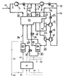
- Gas 1 to be liquefied is converted into a gas at approximately atmospheric pressure Liquefaction heat exchanger 41 introduced and liquefied there. Via line 2 the liquid product is supplied to a consumer and / or a liquid tank.
- a cycle medium 35 becomes less than atmospheric Pressure fed to a feed gas compressor 3 with aftercooler 4 and there to one Intermediate pressure of, for example, 3 to 8 bar, preferably 4 to 6 bar, compressed. Under this pressure, two further streams 6, 7 of the circulating medium admixed.
- the combined gas stream 8 is in a circuit compressor 9 with Aftercooler 10 to a high pressure of, for example, 24 to 33 bar, preferably 26 to 31 bar compressed.
- a first partial flow 12 of the high pressure gas 11 is in a cycle heat exchanger 13 cooled to a first intermediate temperature and then in a warm turbine 14 relaxed while working to about the intermediate pressure.
- the relaxed first partial stream of the circulating medium flows via lines 15, 7 and 8 through the circuit heat exchanger 13 to the inlet of the circuit compressor 9 back.
- a second (22) and third (23) partial flow of high pressure gas 11 are initially together (16) in the series-connected post-compressors 17, 19 with after-coolers 18, 20 to an even higher pressure of, for example, 50 to 70 bar, preferably Brought 60 to 65 bar, which prevails in line 21.
- the second Partial flow 22 in the circuit heat exchanger 13 to a second, lower one Cooled intermediate temperature and then in a cold turbine 24 relaxed workload to about the intermediate pressure.
- the resulting two-phase mixture 25 is in an intermediate pressure separator (phase separator) 26th introduced. Steam from the intermediate pressure separator 26 flows over the lines 27, 6 and 8 through the circuit heat exchanger 13 to the inlet of the circuit compressor 9 back.
- the third partial flow 23 is up to the cold end of the circuit heat exchanger 13 out, then throttle relaxed to about the intermediate pressure (28) and over Line 29 introduced into the intermediate pressure separator (phase separator) 26.
- the Liquid 30 is further expanded to approximately atmospheric pressure (31) and in one Low-pressure separator 32 is subjected to a further phase separation.
- the remaining liquid 40 flows into the liquefaction heat exchanger 41 while the flash gas via lines 34, 35 and 2 through the circuit heat exchanger 13 flows back to the inlet of the feed gas compressor 3.
- the liquid circulating medium 40 is in the liquefaction heat exchanger Essentially completely evaporated.
- the gas 42 formed thereby flows over the Lines 43 34, 35 and 2 through the circuit heat exchanger 13 to the entry of Feedgas compressor 3 back.
- Losses of circulating medium are calculated on the Lines 44 and / or 45 are filled up with warm circulating medium from time to time 44 or cold circulating medium 45 - for example from a tank or one Low-temperature air separation plant is fed.
- the liquefaction heat exchanger 41 has only one Group of liquefaction passages on.
- gaseous oxygen for example from a tank or a low-temperature air separation plant - Via line 1 to the condensation heat exchanger 41 and thus generates liquid oxygen in line 2.
- a switching process if necessary with flushing of lines 1, 2) can be in a second Operating state to be changed in the line 1 with a source of gaseous Nitrogen is connected, for example, also in a low-temperature air separation plant located.
- this second operating state is then in line 2 liquid nitrogen generated.
- the circulating medium has in both operating states the same composition.
- lines 1a and 2a shown in dashed lines are for a second variant of the inventive method necessary in the same time liquid oxygen (Lines 1, 2) and liquid nitrogen (lines 1a, 2a) is obtained.
Landscapes
- Engineering & Computer Science (AREA)
- Physics & Mathematics (AREA)
- Mechanical Engineering (AREA)
- Thermal Sciences (AREA)
- General Engineering & Computer Science (AREA)
- Health & Medical Sciences (AREA)
- Emergency Medicine (AREA)
- Separation By Low-Temperature Treatments (AREA)
Abstract
Das Verfahren und die Vorrichtung dienen zur gleichzeitigen oder aufeinander folgenden Erzeugung von flüssigem Sauerstoff und flüssigem Stickstoff. Zu verflüssigendes Gas (Sauerstoff und/oder Stickstoff 1, 1a) wird in einem Verflüssigungs-Wärmetauscher (41) durch indirekten Wärmeaustausch mit einem Kreislaufmedium (40) verflüssigt. Das Kreislaufmedium wird in einem Kältekreislauf verdichtet (3, 9), abgekühlt (13), arbeitsleistend entspannt (14, 24) und mindestens teilweise verflüssigt, wieder angewärmt (13) und der Verdichtung (3, 9) zugeführt (6, 7, 15, 25, 27, 34, 35). Das Kreislaufmedium weist einen Argongehalt von mindestens 10 mol% auf. <IMAGE>
Description
Die Erfindung betrifft ein Verfahren zur gleichzeitigen oder aufeinander folgenden
Erzeugung von flüssigem Sauerstoff und flüssigem Stickstoff, bei dem zu
verflüssigendes Gas in einem Verflüssigungs-Wärmetauscher durch indirekten
Wärmeaustausch mit einem Kreislaufmedium verflüssigt wird, wobei das
Kreislaufmedium in einem Kältekreislauf verdichtet, abgekühlt, arbeitsleistend
entspannt und mindestens teilweise verflüssigt, wieder angewärmt und der Verdichtung
zugeführt wird.
Stickstoff-Verfiüssigungsverfahren mit Kältekreislauf sind allgemein bekannt, zum
Beispiel aus DE 2548222 B, DE 3732364 A, EP 316768 A, DE 4030750 A,
DE 4303771 A, DE 4418435 A, EP 795727 A oder EP 949471 A. Aus US 5678425 ist
außerdem bekannt, ein derartiges Verfahren in zwei unterschiedlichen
Betriebszuständen zu betreiben. Im einen Betriebszustand wird ausschließlich
Flüssigstickstoff produziert, im anderen Flüssigstickstoff und Flüssigsauerstoff. In
beiden Fällen wird Luft als Kreislaufmedium eingesetzt.
Der Erfindung liegt die Aufgabe zugrunde, ein Verfahren der eingangs genannten Art
und eine entsprechende Vorrichtung anzugeben, die für die Produktion von flüssigem
Sauerstoff und flüssigem Stickstoff geeignet sind und einen besonders niedrigen
Energieverbrauch aufweisen. Die Verflüssigung von Sauerstoff und Stickstoff kann
dabei entweder gleichzeitig oder zeitlich versetzt in verschiedenen Betriebszuständen
erfolgen.
Diese Aufgabe wird dadurch gelöst, dass das Kreislaufmedium einen Argongehalt von
mindestens 10 mol% aufweist.
Durch den Verzicht auf die Verwendung von Luft oder im Wesentlichen reinem
Stickstoff als Kreislauf-Fluid kann der Kälteerzeugungs- und Verflüssigungsprozess
optimal an das zu verflüssigende Gas angepasst werden, um einen möglichst geringen
Energieverbrauch bei der Verflüssigung zu erzielen. Gleichzeitig oder zu
verschiedenen Zeitpunkten (erster und zweiter Betriebszustand) können dabei in
derselben Anlage unterschiedliche Flüssigprodukte gewonnen werden (Stickstoff und
Sauerstoff), ohne dass bei der Wirtschaftlichkeit des Prozesses Abstriche gemacht
werden müssen. Beispielsweise wird bei der Erzeugung von flüssigem Sauerstoff 5 %
weniger Energie verbraucht, wenn als Kreislaufmedium Argon oder ein Argon und
Sauerstoff enthaltendes Gemisch anstelle von Stickstoff verwendet wird.
Vorzugsweise weist das Kreislaufmedium einen Argongehalt von mindestens 50 mol%,
insbesondere mindestens 80 mol%, insbesondere mindestens 95 mol%, auf. Es kann
beispielsweise durch gasförmiges Roh- oder Reinargon aus einer Tieftemperatur-Luftzerlegungsanlage
oder durch eine entsprechende Flüssigkeit aus einem
Speichertank gebildet werden.
In einer ersten Variante des erfindungsgemäßen Verfahrens werden Sauerstoff und
Stickstoff gleichzeitig als zu verflüssigende Gase in den Verflüssigungs-Wärmetauscher
eingeleitet. Der Verflüssigungs-Wärmetauscher enthält also getrennte
Gruppen von Passagen für Sauerstoff und Stickstoff.
Gemäß einer zweiten Variante der Erfindung wird in einem ersten Betriebszustand
Sauerstoff als zu verflüssigendes Gas in den Verflüssigungs-Wärmetauscher
eingeleitet und in einem zweiten Betriebszustand wird Stickstoff als zu verflüssigendes
Gas in den Verflüssigungs-Wärmetauscher eingeleitet. Der Verflüssigungs-Wärmetauscher
braucht hier nur eine Gruppe von Passagen für zu verflüssigendes
Gas aufzuweisen, die zwischen Sauerstoff und Stickstoff umgeschaltet werden.
Das zu verflüssigende Gas wird vorzugsweise in beiden Betriebszuständen aus einer
Luftzerlegungsanlage, insbesondere einer Tieftemperatur-Luftzerlegungsanlage,
entnommen.
Die Erfindung betrifft außerdem eine Vorrichtung zur Erzeugung von flüssigem
Sauerstoff und/oder flüssigem Stickstoff gemäß den Patentansprüchen 6 bis 9.
Die Erfindung sowie weitere Einzelheiten der Erfindung werden im Folgenden anhand
eines Ausführungsbeispiele, das in der Zeichnungen schematisch dargestellt ist, näher
erläutert.
Zu verflüssigendes Gas 1 wird unter etwa atmosphärischem Druck in einen
Verflüssigungs-Wärmetauscher 41 eingeführt und dort verflüssigt. Über Leitung 2 wird
das Flüssigprodukt einem Verbraucher und/oder einem Flüssigtank zugeleitet.
In einem Kältekreislauf wird ein Kreislaufmedium 35 unter etwa atmosphärischem
Druck einem Feedgas-Verdichter 3 mit Nachkühler 4 zugeführt und dort auf einen
Zwischendruck von beispielsweise 3 bis 8 bar, vorzugsweise 4 bis 6 bar komprimiert.
Unter diesem Druck werden zwei weitere Ströme 6, 7 des Kreislaufmediums
zugemischt. Der kombinierte Gasstrom 8 wird in einem Kreislauf-Verdichter 9 mit
Nachkühler 10 auf einen hohen Druck von beispielsweise 24 bis 33 bar, vorzugsweise
26 bis 31 bar verdichtet.
Ein erster Teilstrom 12 des Hochdruckgases 11 wird in einem Kreislauf-Wärmetauscher
13 auf eine erste Zwischentemperatur abgekühlt und anschließend in
einer warmen Turbine 14 arbeitsleistend auf etwa den Zwischendruck entspannt. Der
entspannte erste Teilstrom des Kreislaufmediums strömt über die Leitungen 15, 7 und
8 durch den Kreislauf-Wärmetauscher 13 zum Eintritt des Kreislauf-Verdichters 9
zurück.
Ein zweiter (22) und dritter (23) Teilstrom des Hochdruckgases 11 werden zunächst
gemeinsam (16) in den seriell geschalteten Nachverdichtern 17, 19 mit Nachkühlern
18, 20 auf einen noch höheren Druck von beispielsweise 50 bis 70 bar, vorzugsweise
60 bis 65 bar gebracht, der in Leitung 21 herrscht. Anschließend wird der zweite
Teilstrom 22 im Kreislauf-Wärmetauscher 13 auf eine zweite, niedrigere
Zwischentemperatur abgekühlt und anschließend in einer kalten Turbine 24
arbeitsleistend auf etwa den Zwischendruck entspannt. Das dabei entstandene Zwei-Phasen-Gemisch
25 wird in einen Zwischendruck-Abscheider (Phasentrenner) 26
eingeführt. Dampf aus dem Zwischendruck-Abscheider 26 strömt über die Leitungen
27, 6 und 8 durch den Kreislauf-Wärmetauscher 13 zum Eintritt des Kreislauf-Verdichters
9 zurück.
Der dritte Teilstrom 23 wird bis zum kalten Ende des Kreislauf-Wärmetauschers 13
geführt, anschließend auf etwa den Zwischendruck drosselentspannt (28) und über
Leitung 29 in den Zwischendruck-Abscheider (Phasentrenner) 26 eingeleitet. Die
Flüssigkeit 30 wird weiter auf etwa Atmosphärendruck entspannt (31) und in einem
Niederdruck-Abscheider 32 einer weiteren Phasentrennung unterworfen. Die
verbleibende Flüssigkeit 40 strömt in den Verflüssigungs-Wärmetauscher 41, während
das Flashgas über die Leitungen 34, 35 und 2 durch den Kreislauf-Wärmetauscher 13
zum Eintritt des Feedgas-Verdichters 3 zurückfließt.
Das flüssige Kreislaufmedium 40 wird in dem Verflüssigungs-Wärmetauscher im
Wesentlichen vollständig verdampft. Das dabei gebildete Gas 42 strömt über die
Leitungen 43 34, 35 und 2 durch den Kreislauf-Wärmetauscher 13 zum Eintritt des
Feedgas-Verdichters 3 zurück. Verluste an Kreislaufmedium werden über die
Leitungen 44 und/oder 45 aufgefüllt, indem von Zeit zu Zeit warmes Kreislaufmedium
44 oder kaltes Kreislaufmedium 45 - zum Beispiel aus einem Tank oder einer
Tieftemperatur-Luftzerlegungsanlage- zugeführt wird.
In einer ersten Variante weist der Verflüssigungs-Wärmetauscher 41 lediglich eine
Gruppe von Verflüssigungspassagen auf. In einem ersten Betriebszustand wird
gasförmiger Sauerstoff - zum Beispiel aus einem Tank oder einer Tieftemperatur-Luftzerlegungsanlage
- über Leitung 1 zum Verflüssigungs-Wärmetauscher 41 geführt
und damit in Leitung 2 flüssiger Sauerstoff erzeugt. Mit einem Umschaltvorgang
(gegebenenfalls mit Spülung der Leitungen 1, 2) kann in einen zweiten
Betriebszustand gewechselt werden, in dem Leitung 1 mit einer Quelle für gasförmigen
Stickstoff verbunden ist, die sich beispielsweise ebenfalls in einer Tieftemperatur-Luftzerlegungsanlage
befindet. In diesem zweiten Betriebszustand wird dann in Leitung
2 flüssiger Stickstoff erzeugt. Das Kreislaufmedium hat in beiden Betriebszuständen
die gleiche Zusammensetzung.
Die gestrichelt dargestellten Leitungen 1a und 2a sind für eine zweite Variante des
erfindungsgemäßen Verfahrens notwendig, in der gleichzeitig flüssiger Sauerstoff
(Leitungen 1, 2) und flüssiger Stickstoff (Leitungen 1a, 2a) gewonnen wird.
Claims (9)
- Verfahren zur gleichzeitigen oder aufeinander folgenden Erzeugung von flüssigem Sauerstoff und flüssigem Stickstoff, bei dem zu verflüssigendes Gas (1, 1a) in einem Verflüssigungs-Wärmetauscher (41) durch indirekten Wärmeaustausch mit einem Kreislaufmedium (40) verflüssigt wird, wobei das Kreislaufmedium in einem Kältekreislauf verdichtet (3,9), abgekühlt (13), arbeitsleistend entspannt (14, 24) und mindestens teilweise verflüssigt, wieder angewärmt (13) und der Verdichtung (3, 9) zugeführt (6, 7, 15, 25, 27, 34, 35) wird, dadurch gekennzeichnet, dass das Kreislaufmedium einen Argongehalt von mindestens 10 mol% aufweist.
- Verfahren nach Anspruch 1, dadurch gekennzeichnet, dass das Kreislaufmedium einen Argongehalt von mindestens 50 mol%, insbesondere mindestens 80 mol%, insbesondere mindestens 95 mol%, aufweist.
- Verfahren nach Anspruch 1 oder 2, dadurch gekennzeichnet, dass Sauerstoff und Stickstoff gleichzeitig als zu verflüssigende Gase in den Verflüssigungs-Wärmetauscher (41) eingeleitet werden.
- Verfahren nach einem der Ansprüche 1 bis 3, dadurch gekennzeichnet, dass in einem ersten Betriebszustand Sauerstoff als zu verflüssigendes Gas (1) in den Verflüssigungs-Wärmetauscher (41) eingeleitet wird und in einem zweiten Betriebszustand Stickstoff als zu verflüssigendes Gas (1) in den Verflüssigungs-Wärmetauscher (41) eingeleitet wird.
- Verfahren nach einem der Ansprüche 1 bis 4, dadurch gekennzeichnet, dass das zu verflüssigende Gas (1, 1a) aus einer Luftzerlegungsanlage, insbesondere einer Tieftemperatur-Luftzerlegungsanlage, entnommen wird.
- Vorrichtung zur gleichzeitigen oder aufeinander folgenden Erzeugung von flüssigem Sauerstoff und flüssigem Stickstoff mit einem ersten Einlass (1, 1a) für Sauerstoffgas und/oder Stickstoffgas, der mit einem Verflüssigungs-Wärmetauscher (41) zur Verflüssigung durch indirekten Wärmeaustausch mit einem Kreislaufmedium (40) verbunden ist, mit einem Kältekreislauf, der einen Kreislauf-Verdichter (3, 9) zur Verdichtung eines Kreislaufmediums, eine Entspannungsmaschine (14, 24) zur arbeitsleistenden Entspannung und einen Kreislauf-Wärmetauscher (13, 213) zur Anwärmung von entspanntem Kreislaufmedium aufweist und mit dem Verflüssigungs-Wärmetauscher (41) verbunden ist, dadurch gekennzeichnet, dass der Kältekreislauf mit einer Quelle für ein Kreislaufmedium verbindbar ist, das einen Argongehalt von mindestens 10 mol% ausweist.
- Vorrichtung nach Anspruch 6, gekennzeichnet durch einen zweiten Einlass für Sauerstoffgas und/oder Stickstoffgas, der mit dem Verflüssigungs-Wärmetauscher (41) verbunden ist.
- Vorrichtung nach Anspruch 6, gekennzeichnet durch eine Einrichtung zum umschaltbaren Verbinden des ersten Einlasses mit einer Quelle für Sauerstoffgas und einer Quelle für Stickstoffgas.
- Vorrichtung nach einem der Ansprüche 6 bis 8, dadurch gekennzeichnet, dass der erste Einlass und/oder der zweite Einlass mit einer Produktleitung einer Luftzerlegungsanlage, insbesondere einer Tieftemperatur-Luftzerlegungsanlage, verbunden ist.
Applications Claiming Priority (2)
| Application Number | Priority Date | Filing Date | Title |
|---|---|---|---|
| DE10158328 | 2001-11-28 | ||
| DE10158328A DE10158328A1 (de) | 2001-11-28 | 2001-11-28 | Verfahren und Vorrichtung zur Erzeugung von flüssigem Sauerstoff und flüssigem Stickstoff |
Publications (1)
| Publication Number | Publication Date |
|---|---|
| EP1316767A1 true EP1316767A1 (de) | 2003-06-04 |
Family
ID=7707235
Family Applications (1)
| Application Number | Title | Priority Date | Filing Date |
|---|---|---|---|
| EP02024689A Withdrawn EP1316767A1 (de) | 2001-11-28 | 2002-11-05 | Verfahren und Vorrichtung zur Erzeugung von flüssigem Sauerstoff und flüssigem Stickstoff |
Country Status (2)
| Country | Link |
|---|---|
| EP (1) | EP1316767A1 (de) |
| DE (1) | DE10158328A1 (de) |
Cited By (2)
| Publication number | Priority date | Publication date | Assignee | Title |
|---|---|---|---|---|
| CN114484263A (zh) * | 2022-01-07 | 2022-05-13 | 首钢京唐钢铁联合有限责任公司 | 一种氮氧液化装置自动变负荷方法及系统 |
| WO2022106801A3 (en) * | 2020-11-21 | 2022-08-04 | Gasconsult Limited | Process for producing liquefied hydrogen |
Citations (5)
| Publication number | Priority date | Publication date | Assignee | Title |
|---|---|---|---|---|
| US3285028A (en) * | 1964-01-06 | 1966-11-15 | Air Prod & Chem | Refrigeration method |
| US4345925A (en) * | 1980-11-26 | 1982-08-24 | Union Carbide Corporation | Process for the production of high pressure oxygen gas |
| WO1990008295A1 (en) * | 1989-01-12 | 1990-07-26 | Eric Murray Smith | Method and apparatus for the production of liquid oxygen and liquid hydrogen |
| EP0816784A1 (de) * | 1996-06-26 | 1998-01-07 | Crio & Eng S.r.l. | Vorrichtung zur Fraktionierung von Luft oder Sauerstoffstickstoff Gasgemischen zur Gewinnung von Stickstoff und Sauerstoff oder von Stickstoff |
| EP1016839A2 (de) * | 1998-12-30 | 2000-07-05 | Praxair Technology, Inc. | Lastabhängiger Tieftemperaturkühlkreislauf |
-
2001
- 2001-11-28 DE DE10158328A patent/DE10158328A1/de not_active Withdrawn
-
2002
- 2002-11-05 EP EP02024689A patent/EP1316767A1/de not_active Withdrawn
Patent Citations (5)
| Publication number | Priority date | Publication date | Assignee | Title |
|---|---|---|---|---|
| US3285028A (en) * | 1964-01-06 | 1966-11-15 | Air Prod & Chem | Refrigeration method |
| US4345925A (en) * | 1980-11-26 | 1982-08-24 | Union Carbide Corporation | Process for the production of high pressure oxygen gas |
| WO1990008295A1 (en) * | 1989-01-12 | 1990-07-26 | Eric Murray Smith | Method and apparatus for the production of liquid oxygen and liquid hydrogen |
| EP0816784A1 (de) * | 1996-06-26 | 1998-01-07 | Crio & Eng S.r.l. | Vorrichtung zur Fraktionierung von Luft oder Sauerstoffstickstoff Gasgemischen zur Gewinnung von Stickstoff und Sauerstoff oder von Stickstoff |
| EP1016839A2 (de) * | 1998-12-30 | 2000-07-05 | Praxair Technology, Inc. | Lastabhängiger Tieftemperaturkühlkreislauf |
Cited By (2)
| Publication number | Priority date | Publication date | Assignee | Title |
|---|---|---|---|---|
| WO2022106801A3 (en) * | 2020-11-21 | 2022-08-04 | Gasconsult Limited | Process for producing liquefied hydrogen |
| CN114484263A (zh) * | 2022-01-07 | 2022-05-13 | 首钢京唐钢铁联合有限责任公司 | 一种氮氧液化装置自动变负荷方法及系统 |
Also Published As
| Publication number | Publication date |
|---|---|
| DE10158328A1 (de) | 2003-06-18 |
Similar Documents
| Publication | Publication Date | Title |
|---|---|---|
| EP0093448B1 (de) | Verfahren und Vorrichtung zur Gewinnung von gasförmigem Sauerstoff unter erhöhtem Druck | |
| DE69004773T2 (de) | Kühlverfahren, der angewandte Kühlkreislauf und seine Anwendung in der Lufttrennung. | |
| DE69210009T2 (de) | Hochdrucklufttrennungszyklen, mit mehrfachem Aufkocher und Doppelkolonne und ihre Integration in Gasturbinen | |
| DE69504735T2 (de) | Verfahren und Anlage zur Herstellung von Kohlenmonoxyd | |
| DE69012923T2 (de) | Verfahren und Vorrichtung zur Herstellung von Stickstoff aus Luft. | |
| EP1067345B1 (de) | Verfahren und Vorrichtung zur Tieftemperaturzerlegung von Luft | |
| EP0701968B1 (de) | Verfahren zum Gewinnen einer Kohlenmonoxid-Reinfraktion | |
| EP1284404A1 (de) | Verfahren und Vorrichtung zur Gewinnung eines Druckprodukts durch Tieftemperaturzerlegung von Luft | |
| EP2313724A2 (de) | Verfahren und vorrichtung zur tieftemperaturzerlegung von luft | |
| DE69420882T2 (de) | Verfahren und Vorrichtung zur Herstellung von gasförmigem Sauerstoff und/oder gasförmigem Stickstoff unter Druck durch Zerlegung von Luft | |
| EP1074805B1 (de) | Verfahren und Vorrichtung zur Gewinnung von Sauerstoff unter überatmosphärischem Druck | |
| DE69900516T2 (de) | Verfahren und Anlage zur kombinierter Herstellung einer Ammoniak-Synthesemischung und Kohlenmonoxyd | |
| DE69209835T2 (de) | Einsäulenluftzerlegungszyklus und dessen Integration in Gasturbinen | |
| EP0363861B1 (de) | Verfahren zur Gewinnung von Rohargon | |
| DE69410584T2 (de) | Verfahren und Einrichtung zur Gasverflüssigung | |
| DE19541339B4 (de) | Verfahren zum Gewinnen von Kohlenmonoxid | |
| DE1046640B (de) | Verfahren und Einrichtung zur Kaelteerzeugung durch arbeitsleistende Entspannung | |
| DE1815532A1 (de) | Verfahren zum Erzeugen von Kaelte | |
| DE69410040T2 (de) | Verfahren und Einrichtung zur Herstellung von wenigstens einem durch Zerlegung von Luft gewonnenem Gas unter Druck | |
| EP1189001B1 (de) | Verfahren und Vorrichtung zur Erzeugung hoch reinen Stickstoffs durch Tieftemperatur-Luftzerlegung | |
| DE10158328A1 (de) | Verfahren und Vorrichtung zur Erzeugung von flüssigem Sauerstoff und flüssigem Stickstoff | |
| EP0081849B1 (de) | Verfahren und Vorrichtung zum Zerlegen von Syntheseabgas | |
| EP1209431B1 (de) | Verfahren und Vorrichtung zur Erzeugung von Sauerstoff und Stickstoff | |
| DE955867C (de) | Verfahren zum Trennen eines verdichteten, wasserstofreichen Gasgemisches | |
| DE10147047A1 (de) | Zwei-oder Drei-Turbinen-Kreislauf zur Erzeugung eines Flüssigkeitsprodukts |
Legal Events
| Date | Code | Title | Description |
|---|---|---|---|
| PUAI | Public reference made under article 153(3) epc to a published international application that has entered the european phase |
Free format text: ORIGINAL CODE: 0009012 |
|
| AK | Designated contracting states |
Designated state(s): AT BE BG CH CY CZ DE DK EE ES FI FR GB GR IE IT LI LU MC NL PT SE SK TR |
|
| AX | Request for extension of the european patent |
Extension state: AL LT LV MK RO SI |
|
| 17P | Request for examination filed |
Effective date: 20031107 |
|
| AKX | Designation fees paid |
Designated state(s): AT BE BG CH CY CZ DE DK EE ES FI FR GB GR IE IT LI LU MC NL PT SE SK TR |
|
| STAA | Information on the status of an ep patent application or granted ep patent |
Free format text: STATUS: THE APPLICATION HAS BEEN WITHDRAWN |
|
| 18W | Application withdrawn |
Effective date: 20050304 |