EP1316717A2 - Dispositif d'injection de carburant pour un moteur à combustion interne - Google Patents
Dispositif d'injection de carburant pour un moteur à combustion interne Download PDFInfo
- Publication number
- EP1316717A2 EP1316717A2 EP02022359A EP02022359A EP1316717A2 EP 1316717 A2 EP1316717 A2 EP 1316717A2 EP 02022359 A EP02022359 A EP 02022359A EP 02022359 A EP02022359 A EP 02022359A EP 1316717 A2 EP1316717 A2 EP 1316717A2
- Authority
- EP
- European Patent Office
- Prior art keywords
- pressure chamber
- injection
- control valve
- control
- chamber
- Prior art date
- Legal status (The legal status is an assumption and is not a legal conclusion. Google has not performed a legal analysis and makes no representation as to the accuracy of the status listed.)
- Granted
Links
Images


Classifications
-
- F—MECHANICAL ENGINEERING; LIGHTING; HEATING; WEAPONS; BLASTING
- F02—COMBUSTION ENGINES; HOT-GAS OR COMBUSTION-PRODUCT ENGINE PLANTS
- F02M—SUPPLYING COMBUSTION ENGINES IN GENERAL WITH COMBUSTIBLE MIXTURES OR CONSTITUENTS THEREOF
- F02M61/00—Fuel-injectors not provided for in groups F02M39/00 - F02M57/00 or F02M67/00
- F02M61/16—Details not provided for in, or of interest apart from, the apparatus of groups F02M61/02 - F02M61/14
- F02M61/20—Closing valves mechanically, e.g. arrangements of springs or weights or permanent magnets; Damping of valve lift
- F02M61/205—Means specially adapted for varying the spring tension or assisting the spring force to close the injection-valve, e.g. with damping of valve lift
-
- F—MECHANICAL ENGINEERING; LIGHTING; HEATING; WEAPONS; BLASTING
- F02—COMBUSTION ENGINES; HOT-GAS OR COMBUSTION-PRODUCT ENGINE PLANTS
- F02M—SUPPLYING COMBUSTION ENGINES IN GENERAL WITH COMBUSTIBLE MIXTURES OR CONSTITUENTS THEREOF
- F02M45/00—Fuel-injection apparatus characterised by having a cyclic delivery of specific time/pressure or time/quantity relationship
- F02M45/02—Fuel-injection apparatus characterised by having a cyclic delivery of specific time/pressure or time/quantity relationship with each cyclic delivery being separated into two or more parts
- F02M45/04—Fuel-injection apparatus characterised by having a cyclic delivery of specific time/pressure or time/quantity relationship with each cyclic delivery being separated into two or more parts with a small initial part, e.g. initial part for partial load and initial and main part for full load
-
- F—MECHANICAL ENGINEERING; LIGHTING; HEATING; WEAPONS; BLASTING
- F02—COMBUSTION ENGINES; HOT-GAS OR COMBUSTION-PRODUCT ENGINE PLANTS
- F02M—SUPPLYING COMBUSTION ENGINES IN GENERAL WITH COMBUSTIBLE MIXTURES OR CONSTITUENTS THEREOF
- F02M47/00—Fuel-injection apparatus operated cyclically with fuel-injection valves actuated by fluid pressure
- F02M47/02—Fuel-injection apparatus operated cyclically with fuel-injection valves actuated by fluid pressure of accumulator-injector type, i.e. having fuel pressure of accumulator tending to open, and fuel pressure in other chamber tending to close, injection valves and having means for periodically releasing that closing pressure
- F02M47/027—Electrically actuated valves draining the chamber to release the closing pressure
-
- F—MECHANICAL ENGINEERING; LIGHTING; HEATING; WEAPONS; BLASTING
- F02—COMBUSTION ENGINES; HOT-GAS OR COMBUSTION-PRODUCT ENGINE PLANTS
- F02M—SUPPLYING COMBUSTION ENGINES IN GENERAL WITH COMBUSTIBLE MIXTURES OR CONSTITUENTS THEREOF
- F02M57/00—Fuel-injectors combined or associated with other devices
- F02M57/02—Injectors structurally combined with fuel-injection pumps
-
- F—MECHANICAL ENGINEERING; LIGHTING; HEATING; WEAPONS; BLASTING
- F02—COMBUSTION ENGINES; HOT-GAS OR COMBUSTION-PRODUCT ENGINE PLANTS
- F02M—SUPPLYING COMBUSTION ENGINES IN GENERAL WITH COMBUSTIBLE MIXTURES OR CONSTITUENTS THEREOF
- F02M59/00—Pumps specially adapted for fuel-injection and not provided for in groups F02M39/00 -F02M57/00, e.g. rotary cylinder-block type of pumps
- F02M59/20—Varying fuel delivery in quantity or timing
- F02M59/36—Varying fuel delivery in quantity or timing by variably-timed valves controlling fuel passages to pumping elements or overflow passages
- F02M59/366—Valves being actuated electrically
-
- F—MECHANICAL ENGINEERING; LIGHTING; HEATING; WEAPONS; BLASTING
- F02—COMBUSTION ENGINES; HOT-GAS OR COMBUSTION-PRODUCT ENGINE PLANTS
- F02M—SUPPLYING COMBUSTION ENGINES IN GENERAL WITH COMBUSTIBLE MIXTURES OR CONSTITUENTS THEREOF
- F02M63/00—Other fuel-injection apparatus having pertinent characteristics not provided for in groups F02M39/00 - F02M57/00 or F02M67/00; Details, component parts, or accessories of fuel-injection apparatus, not provided for in, or of interest apart from, the apparatus of groups F02M39/00 - F02M61/00 or F02M67/00; Combination of fuel pump with other devices, e.g. lubricating oil pump
- F02M63/0003—Fuel-injection apparatus having a cyclically-operated valve for connecting a pressure source, e.g. constant pressure pump or accumulator, to an injection valve held closed mechanically, e.g. by springs, and automatically opened by fuel pressure
- F02M63/0007—Fuel-injection apparatus having a cyclically-operated valve for connecting a pressure source, e.g. constant pressure pump or accumulator, to an injection valve held closed mechanically, e.g. by springs, and automatically opened by fuel pressure using electrically actuated valves
Definitions
- the invention is based on one Fuel injection device for an internal combustion engine according to the preamble of claim 1.
- This Fuel injector has one High-pressure fuel pump and a connected to it Fuel injector for each cylinder of the Internal combustion engine on.
- the high-pressure fuel pump has one by the internal combustion engine in one stroke driven pump piston on which a pump work space limited with a pressure chamber of the Fuel injector is connectable, the one Injection valve member through which at least one Injection opening is controlled by the in Pressure prevailing pressure against a closing force in an opening direction for releasing the at least one Injection opening is movable.
- a first electric actuated control valve provided between two Switch positions is switchable and by one Connection of the pump work room with a relief room is controlled.
- a second one is electric actuated control valve provided by which in a Control pressure chamber prevailing pressure is controlled by the the injection valve member acts in the closing direction is.
- the control pressure chamber has a connection with the Pump work space on and through the second control valve a connection of the control pressure chamber with a Relief chamber controlled.
- the fuel injection device with the Features according to claim 1 has the advantage that by the first control valve in its first switching position in the pressure room and in the control pressure room also with the Relief room connected pump work room an increased Pressure can be maintained so that regardless of relief of the pump work space by means of the second Control valve a fuel injection, especially for a pre-injection and / or a post-injection can be controlled.
- the pressure build-up for one Main injection can be done through the first control valve be controlled and the time at which the Main injection can begin through the second control valve to be controlled. It is a decoupling between the pressure at which the main injection begins and the time interval to a previous pre-injection allows.
- Training according to claim 3 enables simultaneous relief the pump work space as well as the pressure space and the Control pressure chamber.
- the training according to claim 4 enables a simple way to control the pressure in the Control pressure chamber.
- the training according to claim 5 enables an adjustment of the fuel flow in the Control pressure chamber or the fuel outflow from the Control pressure chamber.
- the training according to claim 6 enables operation of the internal combustion engine with low noise and Schadt substances mission.
- the training according to claim 9 allows easy adjustment of the fuel quantity for the pre-injection by the period for which the first control valve is closed.
- the training according to Claim 10 enables simple and purely mechanical Way, setting the amount of fuel for the Pilot injection.
- the training according to claim 14 enables a post-injection without this during the Pump piston fuel needs to be pumped.
- the Training according to claim 16 enables in a simple manner performing a pre-injection.
- the training according to Claim 17 allows relief of the pressure chamber and the control pressure chamber.
- FIG. 1 shows a Fuel injection device for an internal combustion engine in a schematic representation according to a first Embodiment
- Figure 2 the Fuel injection device according to a section second embodiment
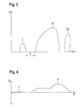
- Figure 3 is a course of a Pressure at an injection port Fuel injector the Fuel injector during an injection cycle
- FIG. 4 shows the course of the speed of a Fuel injector pump piston during an injection cycle.
- FIGs 1 and 2 is one Fuel injection device for an internal combustion engine shown a motor vehicle.
- the internal combustion engine is preferably a self-igniting internal combustion engine.
- the Fuel injector is preferably as so-called pump-nozzle system designed and for each cylinder of the internal combustion engine one High-pressure fuel pump 10 and a connected thereto Fuel injector 12 on, which is an assembly are summarized.
- the Fuel injection device also as a so-called pump-line-nozzle system be trained, also for each cylinder of the internal combustion engine High pressure fuel pump 10 and that Fuel injection valve 12 are provided, but with Are spaced from each other and via a line are interconnected.
- the high pressure fuel pump 10 has one in a cylinder bore 16 of a pump body 14 tightly guided pump piston 18 by a Cam 20 of a camshaft of the internal combustion engine directly or via a transmission element, for example a Rocker arm, against the force of a return spring 19 in a stroke is driven.
- the pump piston 18 delimits a pump work space in the cylinder bore 16 22, in the fuel 18 during the delivery stroke of the pump piston is compressed under high pressure.
- the pump work room 22 is by means of the delivery pressure of a delivery pump 21st Fuel from a fuel tank 9 of the Motor vehicle supplied.
- the fuel injection valve 12 has one with the Pump body 14 connected valve body 26, the can be formed in several parts, in which a Injection valve member 28 in a bore 30 is guided longitudinally.
- the valve body 26 instructs its the combustion chamber of the cylinder of the internal combustion engine facing end region at least one, preferably several Injection openings 32 on.
- the injection valve member 28 has at its end area facing the combustion chamber for example, approximately conical sealing surface 34, which with one in the valve body 26 in its facing the combustion chamber End region trained valve seat 36 cooperates from after or after which the injection openings 32 discharge.
- valve body 26 in the Valve body 26 is between the injection valve member 28 and an annular space 38 toward the bore 30 toward the valve seat 36 available, the one facing away from the valve seat 36 End area through a radial expansion of the bore 30 in a pressure chamber 40 surrounding the injection valve member 28 transforms.
- the injection valve member 28 has the level of Pressure chamber 40 by reducing a cross section Pressure shoulder 42 on.
- Injector member 28 engages a biased one Closing spring 44 through which the injection valve member 28 is pressed towards the valve seat 36.
- the closing spring 44 is arranged in a spring chamber 46 of the valve body 26, the connects to the bore 30.
- the pressure chamber 40 has a connection 54 to the pump workspace 22, the by one through the pump body 14 and the valve body 26 extending channel is formed. Connection 54 will hereinafter referred to as pressure chamber connection 54. Of the Pressure chamber connection 54 branches a connection 56 to Control pressure chamber 52, so that the control pressure chamber 52nd is also connected to the pump work space 22. The Connection 56 is subsequently called the control pressure chamber connection 56 designated.
- the fuel injection device has a first one electrically operated control valve 60 through which one Connection 59 of the pump workspace 22 with a Relief chamber is controlled as the the pressure side of the Feed pump 21 and thus at least indirectly the Fuel tank 9 can serve.
- the connection 59 is subsequently referred to as the relief space connection 59 designated.
- the first control valve 60 is upstream that leading to the control pressure chamber 52 Control pressure chamber connection 56 in the pressure chamber connection 54 arranged.
- the first control valve 60 has an actuator 61, which is a Electromagnet or a piezo actuator can be electrical is controlled and through which a valve member of the Control valve 60 is movable.
- the first control valve 60 can be pressure balanced or not pressure balanced be trained.
- the first control valve 60 is in one Figure 1 illustrated first embodiment as a 3/2-way valve designed and this is between two Switch positions switchable. Through the first control valve 60 is in a first switching position Relief chamber connection 59 to relief chamber 9 opened, so that the pump working space 22 with the relief space 9 is connected while the pressure chamber 40 and the Control pressure chamber 52 are separated from the pump work chamber 22.
- the first Control valve 60 In a second switch position, the first Control valve 60, the relief chamber connection 59 to Relief chamber 9 separated, so that the pump working chamber 22nd is separated from the relief chamber 9, while the pressure chamber 40 and the control pressure chamber 52 with the pump work chamber 22 are connected.
- the first control valve 60 is by a electrical control device 66 depending on Operating parameters of the internal combustion engine between its switched between two switch positions.
- a second electrically operated control valve 68 is provided, through which a connection 70 of the control pressure chamber 52 with a relief space, for example at least indirectly the fuel tank 9 is controlled.
- the Connection 70 is subsequently referred to as a relief space connection 70 designated.
- the second control valve 68 has an actuator 69, which can be an electromagnet or a piezo actuator, which is controlled electrically and by the one Valve member of the control valve 68 is movable.
- the second Control valve 68 is preferably pressure balanced educated.
- the second control valve 68 is a 2/2-way valve trained by the in a first Switch position the relief chamber connection 70 of the Control pressure chamber 52 is opened with the relief chamber 9 and by the in a second switching position Relief chamber connection 70 of the control pressure chamber 52 with the Relief chamber 9 is separated.
- In the Control pressure chamber connection 56 of the control pressure chamber 52 with the A throttle point 58 is provided in the pressure chamber connection 54 and in the relief space connection 70 of the control pressure space 52 with the relief chamber 9 is another throttling point 71 provided.
- the throttling points 58, 71 allow one Adjustment of the inflow of fuel into the Control pressure chamber 52 or the outflow of fuel from the Control pressure chamber 52.
- the second control valve 68 is also controlled by the control device 66.
- the Control of the control valves 60,68 by the Control device 66 takes place depending on operating parameters the internal combustion engine, such as speed, load and temperature.
- Fuel injector The function of Fuel injector explained.
- the suction stroke of the Pump piston 18 is in itself by the feed pump 21 in its first switching position of the first control valve 60, in which the pump work chamber 22 with the feed pump 21 connected and from the pressure chamber 40 and from the control pressure chamber 52 is separated, fuel is supplied to the pump work chamber 22.
- the delivery stroke of the pump piston 18 takes place in one Injection cycle a fuel injection.
- the Injection cycle begins with a pre-injection at which a small amount of fuel at relatively low pressure is injected.
- the first control valve 60 through the Control device 66 in its second switching position brought so that the pump workspace 22 from Relief chamber 9 is separated and the pressure chamber 40 and Control pressure chamber 52 connected to the pump work chamber 22 are.
- the second control valve 68 is by the Control device 66 closed. Through the pump piston 18 is fuel in the pressure chamber 40 and Control pressure chamber 52 promoted. The fuel injector 12 remains meanwhile due to the closed second control valve 68 prevailing in the control pressure chamber 52 Closed. After a certain period of time by the control device 66, the first control valve 60 in brought his first switch position so that the Pump work chamber 22 is connected to the relief chamber 9 and the pressure chamber 40 and the control pressure chamber 52 from Pump work space 22 are separated. In the pressure room 40 and the Control pressure chamber 52 thus remains fuel under pressure saved. At a given time the Control device 66 opened the second control valve 68, see above that the control pressure chamber 52 is relieved and that Injection valve member 28 through the in the pressure chamber 40th prevailing pressure opens.
- the pre-injection takes place with the pressure level below which the fuel in the pressure chamber 40 is saved.
- the first control valve 60 by the control device 66 at the beginning of the delivery stroke of the pump piston 18 in its second switching position is brought so that the pump piston 18 when the second control valve is closed 68 fuel in promotes the pressure chamber 40 and the control pressure chamber 52.
- the first Control valve 60 through the control device 66 in its brought the first switch position so that the pump work space 22 is relieved and the pressure chamber 40 and Control pressure chamber 52 are separated from the pump work chamber 22 and fuel under pressure in the pressure chamber 40 and in Control pressure chamber 52 remains stored.
- Control valve 68 opened so that the control pressure chamber 52nd is relieved and the injection valve member 28 by the im Pressure chamber 40 prevailing pressure opens.
- the pre-injection is ended when the pressure in the pressure chamber 40 is so strong has dropped that by the closing spring 44 on the Injection valve member 28 is greater than the force exerted by the pressure prevailing in the pressure chamber 40 Opening direction on the injection valve member 28 caused Force and the injector member 28 closes.
- the first Control valve 60 through controller 66 to start the delivery stroke of the pump piston 18 into its second Switch position is brought so that the pump work space 22 is separated from the relief chamber 9 and with the pressure chamber 40 and the control pressure chamber 52 is connected.
- the cam 20 has such a shape that through this over a a delivery stroke of the pump piston 18 is caused so that fuel in through the pump piston 18 the pressure chamber 40 and the control pressure chamber 52 closed second control valve 68 is promoted. In a subsequent range of rotation angle of the cam 20 this shaped such that no further delivery stroke of the Pump piston 18 takes place.
- the speed C of the Pump piston 18 in which caused by the cam 20 Stroke movement over the angle of rotation ⁇ of the cam 20 is in Figure 4 shown, the speed when through the stroke caused by the first rotation angle range is denoted by I. is the speed at the following Angle of rotation range of the cam 20 is zero and Speed through a wider range of rotation angles of the cam 20 during a main injection Hubs is designated with II. Due to the shape of the cam 20 in first rotation angle range and the stroke of the Pump piston 18, the amount of fuel is determined by the Pump piston 18 in the pressure chamber 40 and the control pressure chamber 52 is funded.
- the first control valve 60 through the control device 66 into its second Switch position brought and the second control valve 68 is closed by the control device 66.
- the second control valve 68 opened so that the control pressure chamber 52nd is relieved.
- the injection valve member 28 then opens the pressure prevailing in the pressure chamber 40 and the Main injection begins.
- the main injection corresponds an injection phase designated II in FIG. 3.
- the end of the main injection will be the second Control valve 68 closed by the control device 66, so that the control pressure chamber 52 is separated from the relief chamber 9 is and builds up in the control pressure chamber 52 high pressure the injection valve member 28 is closed. additionally can also do the first at the end of the main injection Control valve 60 through the control device 66 in its first switch position are brought.
- the main injection should start with high pressure, so will be the first Control valve 60 by the control device 66 according to the Pre-injection early from its first Switch position switched to its second switch position, so that pressure builds up.
- the time interval of the The main injection from the pre-injection is made by the Time of opening of the second control valve 68 by the Control device 66 determines. If the main injection Should start with a little pressure, so will be the first Control valve 60 by the control device 66 according to the Pre-injection closed at a later time, see above that there is a correspondingly delayed build-up of pressure.
- the time interval of the main injection from the Pre-injection is in turn determined by the time of the Opening of the second control valve 68 is determined.
- the second Control valve 68 through the control device 66 before The beginning of the main injection is opened so that the Control pressure chamber 52 is relieved.
- the first control valve 60 is in its second by the control device 66 Switch position and the main injection begins, if the pressure in the pressure chamber 40 is so high that this Injection valve member 28 against the force of the closing spring 44 opens.
- the second one Control valve 68 closed by the control device 66 and / or the first control valve 60 is in its first Switch position brought.
- the Main injection can with the second closed Control valve 68 and in its first switching position located first control valve 60 fuel in the pressure chamber 40 and stored in the control pressure chamber 52.
- the height the pressure under which the fuel is stored by the time of closing the second control valve 68 determined at the end of the main injection. ever the earlier the second control valve 68 is closed, the more higher is the pressure under which the fuel in the pressure chamber 40 and stored in the control pressure chamber 52.
- the second control valve 68 through the Control device 66 opened again so that the Control pressure chamber 52 is relieved and that Injection valve member 28 opens.
- the post-injection corresponds to one designated by III in FIG Injection phase.
- the post-injection is ended by the second control valve 68 by the control device 66 is closed. You can also have several consecutive Post-injections take place.
- the one at post-injection injected fuel does not need at the time of Post-injection can be promoted by the pump piston 18, but becomes the pressure chamber 40 and the control pressure chamber 52 taken into which the fuel through the pump piston 18th promoted by its production stroke in an earlier phase has been.
- the first control valve 60 can after completion of the Main injection remain in its first switch position.
- the first can be used for post-injection Control valve 60 through the control device 66 in its second switching position are brought so that by the Pump piston 18 fuel is pumped into the pressure chamber 40 becomes. If in the pressure chamber 40 and the control pressure chamber 52 of the previous main injection still fuel is stored, the pump piston 18 needs during the post-injection only part of that for the Post-injection required amount of fuel promoted become. If when the second control valve 68 and the pressure in the pressure chamber is thus relieved of the control pressure chamber 52 40 is so high that the opening force on the Injection valve member 28 is larger than that on this effective closing force, the post-injection begins.
- the Post injection is stopped by the second control valve 68 is closed by the control device 66 and / or when the pressure in the pressure chamber 40 has dropped so much that the closing force on the injection valve member 28 is greater than that generated by the pressure in the pressure chamber 40 Opening force and the injection valve member 28 closes.
- the second Control valve 68 closed by the control device 66 is and remains closed until the pressure in the Pressure chamber 40 has dropped so much as a result of the leakage that the injection valve member 28 even when the second one is open Control valve 68 can no longer open. Then will the second control valve 68 briefly opened so that the Pressure chamber 40 and the control pressure chamber 52 are relieved.
- the fuel injection device is according to shown a second embodiment in which compared to the first embodiment, only the training of the first control valve 160 is modified.
- the first Control valve 160 is designed as a 3/3-way valve and can be switched between three switch positions. In a first switching position of the control valve 160 is through this the pump working space 22 with the feed pump 21 or the Relief chamber 9 connected and the pressure chamber 40 and Control pressure chamber 52 are separated from the pump work chamber 22. In a second switching position of the control valve 160 through this the pump working space 22 from the feed pump 21 or the relief chamber 9 separately and the pressure chamber 40 and the control pressure chamber 52 are with the pump work chamber 22 connected.
- a third switching position of the control valve 160 is through this the pump working space 22 with the Feed pump 21 and the relief chamber 9 connected and the Pressure chamber 40 and control pressure chamber 52 are also included the feed pump 21 or the relief chamber 9 connected.
- the first switching position of the control valve 160 thus has the same function as the first switch position of the Control valve 60 according to the first embodiment and the second switching position of the control valve 160 has the same function as the second switch position of the Control valve 60 according to the first embodiment.
- the fuel injector can thus function also with the control valve 160 according to the second Embodiment can be achieved.
- With the third Switch position of the control valve 160 is a relief of Pump work room 22 and the pressure chamber 40 and the Control pressure chamber 52 allows.
- the first control valve 160 to terminate a Fuel injection, that is pre-injection and / or the main injection and / or the Post-injection, by the control device 66 in its third switching position is brought, which makes a quick Relief of the pressure chamber 40 and the control pressure chamber 52 is achieved and thus a quick closing of the Injection valve member 28 to end the Fuel injection. It can be provided that for Switching of the first control valve 160, its actuator 161 through the control device 66 with different Current levels is energized.
- control valve 160 If the actuator 161 is de-energized, so the control valve 160 is in its first Switch position when the actuator 161 is raised Current level is energized, the control valve 160 in switched its third switching position and when the actuator 161 is energized with a further increased current level, so the control valve 160 is in its second switching position switched.
Landscapes
- Engineering & Computer Science (AREA)
- Chemical & Material Sciences (AREA)
- Combustion & Propulsion (AREA)
- Mechanical Engineering (AREA)
- General Engineering & Computer Science (AREA)
- Physics & Mathematics (AREA)
- Fluid Mechanics (AREA)
- Fuel-Injection Apparatus (AREA)
Applications Claiming Priority (2)
| Application Number | Priority Date | Filing Date | Title |
|---|---|---|---|
| DE10158659 | 2001-11-30 | ||
| DE10158659A DE10158659A1 (de) | 2001-11-30 | 2001-11-30 | Kraftstoffeinspritzeinrichtung für eine Brennkraftmaschine |
Publications (3)
| Publication Number | Publication Date |
|---|---|
| EP1316717A2 true EP1316717A2 (fr) | 2003-06-04 |
| EP1316717A3 EP1316717A3 (fr) | 2003-11-26 |
| EP1316717B1 EP1316717B1 (fr) | 2005-08-24 |
Family
ID=7707433
Family Applications (1)
| Application Number | Title | Priority Date | Filing Date |
|---|---|---|---|
| EP02022359A Expired - Lifetime EP1316717B1 (fr) | 2001-11-30 | 2002-10-08 | Dispositif d'injection de carburant pour un moteur à combustion interne |
Country Status (4)
| Country | Link |
|---|---|
| US (1) | US6808124B2 (fr) |
| EP (1) | EP1316717B1 (fr) |
| JP (1) | JP2003172229A (fr) |
| DE (2) | DE10158659A1 (fr) |
Cited By (1)
| Publication number | Priority date | Publication date | Assignee | Title |
|---|---|---|---|---|
| US7455243B2 (en) * | 2004-03-03 | 2008-11-25 | Caterpillar Inc. | Electronic unit injector with pressure assisted needle control |
Families Citing this family (10)
| Publication number | Priority date | Publication date | Assignee | Title |
|---|---|---|---|---|
| DE10205750A1 (de) * | 2002-02-12 | 2003-08-21 | Bosch Gmbh Robert | Kraftstoffeinspritzeinrichtung für eine Brennkraftmaschine |
| DE10213025B4 (de) * | 2002-03-22 | 2014-02-27 | Daimler Ag | Selbstzündende Brennkraftmaschine |
| US7191762B2 (en) * | 2002-03-26 | 2007-03-20 | Volvo Lastvagnar Ab | Fuel injection system |
| EP1359316B1 (fr) * | 2002-05-03 | 2007-04-18 | Delphi Technologies, Inc. | Système d'injection de carburant |
| WO2004072470A1 (fr) * | 2003-02-12 | 2004-08-26 | Robert Bosch Gmbh | Systeme de pompe d'injection de carburant comportant un mecanisme de post-injection haute pression |
| FR2871197B1 (fr) * | 2004-06-04 | 2006-07-28 | Renault V I Sa | Injecteur pompe |
| DE102004028195A1 (de) * | 2004-06-09 | 2005-12-29 | Volkswagen Mechatronic Gmbh & Co. Kg | Einspritzventil mit Schließdruckbeaufschlagung der Ventilnadel |
| US20060196974A1 (en) * | 2005-03-01 | 2006-09-07 | Caterpillar Inc. | Fuel injector having a gradually restricted drain passageway |
| DE102005014180A1 (de) * | 2005-03-29 | 2006-10-05 | Robert Bosch Gmbh | Kraftstoffeinspritzeinrichtung für eine Brennkraftmaschine |
| GB2560513A (en) * | 2017-03-13 | 2018-09-19 | Ap Moeller Maersk As | Fuel injection system |
Citations (1)
| Publication number | Priority date | Publication date | Assignee | Title |
|---|---|---|---|---|
| EP0957261A2 (fr) | 1998-05-15 | 1999-11-17 | LUCAS INDUSTRIES public limited company | Système de carburant et pompe utilisable dans ce système |
Family Cites Families (6)
| Publication number | Priority date | Publication date | Assignee | Title |
|---|---|---|---|---|
| DE4118236C2 (de) * | 1990-06-06 | 2000-02-17 | Avl Verbrennungskraft Messtech | Einspritzsystem für Brennkraftmaschinen |
| US5443047A (en) * | 1993-04-09 | 1995-08-22 | Zexel Corporation | Fuel injection system |
| JP2885076B2 (ja) * | 1994-07-08 | 1999-04-19 | 三菱自動車工業株式会社 | 蓄圧式燃料噴射装置 |
| GB9622335D0 (en) * | 1996-10-26 | 1996-12-18 | Lucas Ind Plc | Injector arrangement |
| US5826561A (en) * | 1996-12-10 | 1998-10-27 | Caterpillar Inc. | Method and apparatus for injecting fuel using control fluid to control the injection's pressure and time |
| DE19939429A1 (de) * | 1999-08-20 | 2001-03-01 | Bosch Gmbh Robert | Kraftstoffeinspritzeinrichtung |
-
2001
- 2001-11-30 DE DE10158659A patent/DE10158659A1/de not_active Withdrawn
-
2002
- 2002-10-08 DE DE50204013T patent/DE50204013D1/de not_active Expired - Lifetime
- 2002-10-08 EP EP02022359A patent/EP1316717B1/fr not_active Expired - Lifetime
- 2002-11-26 US US10/303,703 patent/US6808124B2/en not_active Expired - Fee Related
- 2002-11-29 JP JP2002348845A patent/JP2003172229A/ja not_active Abandoned
Patent Citations (1)
| Publication number | Priority date | Publication date | Assignee | Title |
|---|---|---|---|---|
| EP0957261A2 (fr) | 1998-05-15 | 1999-11-17 | LUCAS INDUSTRIES public limited company | Système de carburant et pompe utilisable dans ce système |
Cited By (1)
| Publication number | Priority date | Publication date | Assignee | Title |
|---|---|---|---|---|
| US7455243B2 (en) * | 2004-03-03 | 2008-11-25 | Caterpillar Inc. | Electronic unit injector with pressure assisted needle control |
Also Published As
| Publication number | Publication date |
|---|---|
| EP1316717A3 (fr) | 2003-11-26 |
| EP1316717B1 (fr) | 2005-08-24 |
| JP2003172229A (ja) | 2003-06-20 |
| US6808124B2 (en) | 2004-10-26 |
| DE50204013D1 (de) | 2005-09-29 |
| US20030101968A1 (en) | 2003-06-05 |
| DE10158659A1 (de) | 2003-06-12 |
Similar Documents
| Publication | Publication Date | Title |
|---|---|---|
| EP1458970B1 (fr) | Dispositif d'injection de carburant pour moteurs a combustion interne | |
| EP1316718A2 (fr) | Dispositif d'injection de carburant pour un moteur à combustion interne | |
| DE10221384A1 (de) | Kraftstoffeinspritzeinrichtung für eine Brennkraftmaschine | |
| EP1316717B1 (fr) | Dispositif d'injection de carburant pour un moteur à combustion interne | |
| EP1241347B1 (fr) | Dispositif d'injection de carburant dans un moteur à combustion interne | |
| EP1260700B1 (fr) | Système d'injection de carburant pour moteur à combustion interne | |
| DE10113654A1 (de) | Kraftsotffeinspritzeinrichtung für Brennkraftmaschinen | |
| EP1260705B1 (fr) | Systeme d'injection de carburant pour moteur a combustion interne | |
| DE10205185A1 (de) | Kraftstoffeinspritzeinrichtung für eine Brennkraftmaschine | |
| EP1456525B1 (fr) | Dispositif d'injection de carburant pour moteur a combustion interne | |
| EP1312792B1 (fr) | Dispositif d'injection de carburant pour un moteur à combustion interne | |
| EP1310668B1 (fr) | Système d'injection de carburant pour un moteur à combustion | |
| EP1236884A2 (fr) | Dispositif d'injection de combustible pour moteurs à combustion interne | |
| DE10207045A1 (de) | Kraftstoffeinspritzeinrichtung für eine Brennkraftmaschine | |
| EP1310667A2 (fr) | Système d'injection de carburant pour un moteur à combustion | |
| EP1310666A2 (fr) | Dispositif d'injection de carburant pour un moteur à combustion interne | |
| EP1260702A2 (fr) | Système d'injection de carburant d'un moteur à combustion interne | |
| EP1552138B1 (fr) | Systeme d'injection de carburant destine a un moteur a combustion interne | |
| EP1430219A1 (fr) | Systeme d'injection de carburant pour moteur a combustion interne | |
| WO2003052259A1 (fr) | Dispositif d'injection de carburant conçu pour un moteur a combustion interne | |
| WO2003027481A1 (fr) | Dispositif d'injection de carburant pour un moteur a combustion interne | |
| DE10160256A1 (de) | Kraftstoffeinspritzeinrichtung für eine Brennkraftmaschine |
Legal Events
| Date | Code | Title | Description |
|---|---|---|---|
| PUAI | Public reference made under article 153(3) epc to a published international application that has entered the european phase |
Free format text: ORIGINAL CODE: 0009012 |
|
| AK | Designated contracting states |
Designated state(s): AT BE BG CH CY CZ DE DK EE ES FI FR GB GR IE IT LI LU MC NL PT SE SK TR |
|
| AX | Request for extension of the european patent |
Extension state: AL LT LV MK RO SI |
|
| PUAL | Search report despatched |
Free format text: ORIGINAL CODE: 0009013 |
|
| AK | Designated contracting states |
Kind code of ref document: A3 Designated state(s): AT BE BG CH CY CZ DE DK EE ES FI FR GB GR IE IT LI LU MC NL PT SE SK TR |
|
| AX | Request for extension of the european patent |
Extension state: AL LT LV MK RO SI |
|
| 17P | Request for examination filed |
Effective date: 20040526 |
|
| AKX | Designation fees paid |
Designated state(s): DE ES FR GB IT |
|
| 17Q | First examination report despatched |
Effective date: 20040917 |
|
| GRAP | Despatch of communication of intention to grant a patent |
Free format text: ORIGINAL CODE: EPIDOSNIGR1 |
|
| GRAS | Grant fee paid |
Free format text: ORIGINAL CODE: EPIDOSNIGR3 |
|
| GRAA | (expected) grant |
Free format text: ORIGINAL CODE: 0009210 |
|
| AK | Designated contracting states |
Kind code of ref document: B1 Designated state(s): DE ES FR GB IT |
|
| PG25 | Lapsed in a contracting state [announced via postgrant information from national office to epo] |
Ref country code: ES Free format text: LAPSE BECAUSE OF FAILURE TO SUBMIT A TRANSLATION OF THE DESCRIPTION OR TO PAY THE FEE WITHIN THE PRESCRIBED TIME-LIMIT Effective date: 20050824 Ref country code: IT Free format text: LAPSE BECAUSE OF FAILURE TO SUBMIT A TRANSLATION OF THE DESCRIPTION OR TO PAY THE FEE WITHIN THE PRESCRIBED TIME-LIMIT;WARNING: LAPSES OF ITALIAN PATENTS WITH EFFECTIVE DATE BEFORE 2007 MAY HAVE OCCURRED AT ANY TIME BEFORE 2007. THE CORRECT EFFECTIVE DATE MAY BE DIFFERENT FROM THE ONE RECORDED. Effective date: 20050824 |
|
| REG | Reference to a national code |
Ref country code: GB Ref legal event code: FG4D Free format text: NOT ENGLISH |
|
| REF | Corresponds to: |
Ref document number: 50204013 Country of ref document: DE Date of ref document: 20050929 Kind code of ref document: P |
|
| GBT | Gb: translation of ep patent filed (gb section 77(6)(a)/1977) |
Effective date: 20051219 |
|
| ET | Fr: translation filed | ||
| PLBE | No opposition filed within time limit |
Free format text: ORIGINAL CODE: 0009261 |
|
| STAA | Information on the status of an ep patent application or granted ep patent |
Free format text: STATUS: NO OPPOSITION FILED WITHIN TIME LIMIT |
|
| 26N | No opposition filed |
Effective date: 20060526 |
|
| PGFP | Annual fee paid to national office [announced via postgrant information from national office to epo] |
Ref country code: FR Payment date: 20101109 Year of fee payment: 9 |
|
| PGFP | Annual fee paid to national office [announced via postgrant information from national office to epo] |
Ref country code: GB Payment date: 20101021 Year of fee payment: 9 |
|
| GBPC | Gb: european patent ceased through non-payment of renewal fee |
Effective date: 20111008 |
|
| REG | Reference to a national code |
Ref country code: FR Ref legal event code: ST Effective date: 20120629 |
|
| PG25 | Lapsed in a contracting state [announced via postgrant information from national office to epo] |
Ref country code: GB Free format text: LAPSE BECAUSE OF NON-PAYMENT OF DUE FEES Effective date: 20111008 Ref country code: FR Free format text: LAPSE BECAUSE OF NON-PAYMENT OF DUE FEES Effective date: 20111102 |
|
| PGFP | Annual fee paid to national office [announced via postgrant information from national office to epo] |
Ref country code: DE Payment date: 20131217 Year of fee payment: 12 |
|
| REG | Reference to a national code |
Ref country code: DE Ref legal event code: R119 Ref document number: 50204013 Country of ref document: DE |
|
| PG25 | Lapsed in a contracting state [announced via postgrant information from national office to epo] |
Ref country code: DE Free format text: LAPSE BECAUSE OF NON-PAYMENT OF DUE FEES Effective date: 20150501 |