EP1260702A2 - Système d'injection de carburant d'un moteur à combustion interne - Google Patents
Système d'injection de carburant d'un moteur à combustion interne Download PDFInfo
- Publication number
- EP1260702A2 EP1260702A2 EP02008632A EP02008632A EP1260702A2 EP 1260702 A2 EP1260702 A2 EP 1260702A2 EP 02008632 A EP02008632 A EP 02008632A EP 02008632 A EP02008632 A EP 02008632A EP 1260702 A2 EP1260702 A2 EP 1260702A2
- Authority
- EP
- European Patent Office
- Prior art keywords
- chamber
- valve
- pressure
- control
- pump
- Prior art date
- Legal status (The legal status is an assumption and is not a legal conclusion. Google has not performed a legal analysis and makes no representation as to the accuracy of the status listed.)
- Granted
Links
Images


Classifications
-
- F—MECHANICAL ENGINEERING; LIGHTING; HEATING; WEAPONS; BLASTING
- F02—COMBUSTION ENGINES; HOT-GAS OR COMBUSTION-PRODUCT ENGINE PLANTS
- F02M—SUPPLYING COMBUSTION ENGINES IN GENERAL WITH COMBUSTIBLE MIXTURES OR CONSTITUENTS THEREOF
- F02M63/00—Other fuel-injection apparatus having pertinent characteristics not provided for in groups F02M39/00 - F02M57/00 or F02M67/00; Details, component parts, or accessories of fuel-injection apparatus, not provided for in, or of interest apart from, the apparatus of groups F02M39/00 - F02M61/00 or F02M67/00; Combination of fuel pump with other devices, e.g. lubricating oil pump
- F02M63/0012—Valves
- F02M63/0031—Valves characterized by the type of valves, e.g. special valve member details, valve seat details, valve housing details
- F02M63/0045—Three-way valves
-
- F—MECHANICAL ENGINEERING; LIGHTING; HEATING; WEAPONS; BLASTING
- F02—COMBUSTION ENGINES; HOT-GAS OR COMBUSTION-PRODUCT ENGINE PLANTS
- F02M—SUPPLYING COMBUSTION ENGINES IN GENERAL WITH COMBUSTIBLE MIXTURES OR CONSTITUENTS THEREOF
- F02M45/00—Fuel-injection apparatus characterised by having a cyclic delivery of specific time/pressure or time/quantity relationship
-
- F—MECHANICAL ENGINEERING; LIGHTING; HEATING; WEAPONS; BLASTING
- F02—COMBUSTION ENGINES; HOT-GAS OR COMBUSTION-PRODUCT ENGINE PLANTS
- F02M—SUPPLYING COMBUSTION ENGINES IN GENERAL WITH COMBUSTIBLE MIXTURES OR CONSTITUENTS THEREOF
- F02M47/00—Fuel-injection apparatus operated cyclically with fuel-injection valves actuated by fluid pressure
- F02M47/02—Fuel-injection apparatus operated cyclically with fuel-injection valves actuated by fluid pressure of accumulator-injector type, i.e. having fuel pressure of accumulator tending to open, and fuel pressure in other chamber tending to close, injection valves and having means for periodically releasing that closing pressure
- F02M47/027—Electrically actuated valves draining the chamber to release the closing pressure
-
- F—MECHANICAL ENGINEERING; LIGHTING; HEATING; WEAPONS; BLASTING
- F02—COMBUSTION ENGINES; HOT-GAS OR COMBUSTION-PRODUCT ENGINE PLANTS
- F02M—SUPPLYING COMBUSTION ENGINES IN GENERAL WITH COMBUSTIBLE MIXTURES OR CONSTITUENTS THEREOF
- F02M59/00—Pumps specially adapted for fuel-injection and not provided for in groups F02M39/00 -F02M57/00, e.g. rotary cylinder-block type of pumps
- F02M59/20—Varying fuel delivery in quantity or timing
- F02M59/36—Varying fuel delivery in quantity or timing by variably-timed valves controlling fuel passages to pumping elements or overflow passages
- F02M59/366—Valves being actuated electrically
Definitions
- the invention is based on one Fuel injection device for an internal combustion engine according to the preamble of claim 1.
- Such a fuel injector is due to the EP 0 957 261 A1 is known.
- This Fuel injector has a fuel pump for each cylinder of the internal combustion engine, the one by the internal combustion engine in one stroke driven pump piston, which has a Pump workspace limits the fuel from one Fuel tank is supplied.
- the Pump work space is with a fuel injector connected, which has an injection valve member through which at least one injection opening is controlled and that through the one connected to the pump work room Pressure prevailing pressure against a closing force in Opening direction is movable. It's a first electric controlled control valve provided by one Connection of the pump workspace with the Fuel tank controlled as a relief space becomes.
- the fuel injection device with the Features according to claim 1 has the advantage that through the pressure control valve towards the relief chamber increased pressure is maintained so that the risk of Cavitation is reduced and also the efficiency is improved.
- the pressure control valve enables in addition, a pre-injection in a simple manner limited pressure level.
- FIG. 1 shows a Fuel injection device for an internal combustion engine in a schematic representation according to a first Embodiment
- Figure 2 shows a course of a pressure Injection openings of a fuel injector Fuel injection device
- Figure 3 in sections a modified version of the Fuel injection device
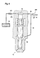
- Figure 4 in sections another modified version of the Krafscherin mousse sensible.
- FIGs 1, 3 and 4 there is one Fuel injection device for an internal combustion engine shown a motor vehicle.
- the internal combustion engine is preferably a self-igniting internal combustion engine.
- the Fuel injector is preferably as so-called pump-line-nozzle system designed and has one for each cylinder of the internal combustion engine Fuel pump 10, a fuel injection valve 12 and a the fuel injector 12 with the Fuel pump 10 connecting line 14.
- the Fuel pump 10 has a seal in a cylinder 16 guided pump piston 18, which by a cam 20th a camshaft of the internal combustion engine against the force a return spring 19 driven in one stroke becomes.
- the pump piston 18 delimits one in the cylinder 16 Pump working space 22 in which the delivery stroke of Pump piston 18 fuel is compressed under high pressure.
- the pump work chamber 22 is one by means of the delivery pressure Feed pump 21 fuel from one Fuel tank 9 of the motor vehicle supplied. It can be provided that by the feed pump 21st Fuel from the fuel tank 9 into one Storage area 24 is promoted in which a pressure according to the delivery pressure of the delivery pump 21, which can be, for example, about 4 to 6 bar. From the Storage area 24 gets fuel during the suction stroke of the Pump piston 18 in the pump work space 22. Between the Storage area 24 and the pump work space 22 is a for Check valve 23 opening pump work chamber 22 arranged. In line 14 is one of the Another check valve 25 opening pump work chamber 22 arranged. The delivery line 13 from the delivery pump 21 opens between the pump working space 22 and the other Check valve 25.
- the pump work space 22 can alternatively also via one through the pump piston 18 controlled connection to the storage area 24 for filling be connectable during the suction stroke of the pump piston 18.
- the Pump piston 18 acts with a control edge with a opening of the connection opening into the pump work chamber 22 to the storage area 24 together by the pump piston 18 is closed or released.
- the check valve 23 can be omitted.
- the fuel injector 12 is separate from the Fuel pump 10 arranged and via line 14 with connected to the pump work space 22.
- the Fuel injection valve 12 has a valve body 26 on, which can be formed in several parts, in which a Injection valve member 28 in a bore 30 is guided longitudinally.
- the valve body 26 instructs its the combustion chamber of the cylinder of the internal combustion engine facing end region at least one, preferably several Injection openings 32 on.
- the injection valve member 28 has at its end area facing the combustion chamber for example, approximately conical sealing surface 34, which with one in the valve body 26 in its facing the combustion chamber End region trained valve seat 36 cooperates from after or after which the injection openings 32 discharge.
- valve body 26 is between the injection valve member 28 and an annular space 38 toward the bore 30 toward the valve seat 36 present, the one facing away from the valve seat 36 End area through a radial expansion of the bore 30 in a pressure chamber 40 surrounding the injection valve member 28 transforms.
- the injection valve member 28 has the level of Pressure chamber 40 by reducing a cross section Pressure shoulder 42 on.
- Injector member 28 engages a biased one Closing spring 44 through which the injection valve member 28 is pressed towards the valve seat 36.
- the closing spring 44 is arranged in a spring chamber 46 of the valve body 26, the connects to the bore 30.
- the Fuel injector has a close to that First control valve 60 arranged on fuel pump 10, that can be integrated into the fuel pump 10, for example can.
- a connection is established by the first control valve 60 59 of the pump workspace 22 of the fuel pump 10 a relief room controlled than the at least indirectly the storage area 24 can serve.
- the connection 59 branches downstream of the check valve 25 from the line 14.
- a pressure maintaining valve 62 is arranged in connection 59.
- the Pressure holding valve 62 has, for example, a Closing spring 63 loaded valve member 64 against the Force of the closing spring 63 to the first control valve 60 in Opening direction is movable. Through the pressure holding valve 62 becomes an increased compared to the pressure in the relief chamber 24 Pressure in line 14 and thus also in pressure chamber 40 maintained.
- the first control valve 60 is electrically controllable and has an actuator 61, which is an electromagnet or Can be a piezo actuator that is controlled electrically and through which a valve member of the control valve 60 is movable.
- the first control valve 60 may or may not be pressure balanced be pressure-balanced.
- the first control valve 60 is designed as a 2/2-way valve and through it in a first switching position, the connection 59 to Relief chamber 24 opened and in a second Switch position becomes the connection 59 to the relief chamber 24 Cut.
- the control valve 60 is operated by an electrical Control device 66 as a function of operating parameters controlled the internal combustion engine.
- a second control valve 68 provided by the one Connection 70 of the control pressure chamber 52 with a Relief space, for example relief space 24, is controlled.
- the second control valve 68 is electrical controllable and has an actuator 69, the one Electromagnet or a piezo actuator can be electrical is controlled and through which a valve member of the Control valve 68 is movable.
- the second control valve 68 is preferably designed to be pressure-balanced.
- the second Control valve 68 is designed as a 2/2-way valve, through the connection 70 in a first switching position of the control pressure chamber 52 opened with the relief chamber 24 is and by the in a second switching position Connection 70 of the control pressure chamber 52 with the Relief chamber 24 is separated.
- connection 59 of the Control pressure chamber 52 with line 14 is one Throttle point 58 is provided and in the connection 70 of the Control pressure chamber 52 with the fuel tank 24 is between the control pressure chamber 52 and the second control valve 68 another throttle point 71 is provided.
- the second Control valve 68 is also operated by the control device 66 controlled. The control of the control valves 60,68 the control device 66 takes place depending on Operating parameters of the internal combustion engine, such as for example speed, load and temperature.
- the pressure control valve 62 opens and fuel flows through the opened first control valve 60 and the connection 59 in the relief room 24. Subsequently, the remains in the Line 14 and the pressure chamber 40 prevailing pressure at least almost constant.
- the opening pressure of the pressure control valve 62 is by the bias of its closing spring 63rd certainly.
- the pre-injection is carried out by a Pressure control valve 62 limited pressure.
- the second Control valve 68 is controlled by control device 66 opened so that in the control pressure chamber 52 despite this Do not build up high pressure at connection 56 with line 14 can, but this is reduced to the relief chamber 24 becomes.
- the throttling points 58 and 71 ensure that from the channel 54 only a small amount of fuel in the Relief chamber 24 can flow away. If the 40 prevailing pressure has reached such a height that this over the pressure shoulder 42 on the Injection valve member 28 acting in the opening direction 29 Exerts force that is greater than the force of the closing spring 44, the injection valve member 28 lifts with his Sealing surface 34 from the valve seat 36 and fuel through the injection openings 32 into the combustion chamber of the Injected cylinders of the internal combustion engine.
- the Opening pressure of the fuel injection valve 12 is at opened second control valve 68 from the force of Closing spring 44 and by the in the control pressure chamber 52nd prevailing residual pressure on the piston 50 generated force dependent.
- the second Control valve 68 closed by the control device 66, so that the control pressure chamber 52 from the relief chamber 24 is separated and located in the control pressure chamber 52 above it Connection 56 with line 14 builds high pressure.
- the piston 50 on the Injection valve member 28 a the force of the closing spring 44th generating supportive power, so that Injection valve member 28 against its opening direction 29 moves and with its sealing surface 34 on the valve seat 36 System comes and the pre-injection is ended.
- the second one Control valve 68 opened by the control device 66, see above that the control pressure chamber 52 is relieved and that Fuel injection valve 12 opens.
- the first control valve 60 can be open at the start of the main injection, so that the connection 59 to the relief chamber 24 is open and in the line 14 and the pressure chamber 40 of the Fuel injector 12 through the pressure control valve 62 predetermined pressure builds up.
- the main injection begins then with a pressure level as well as the pilot injection is done.
- the main injection starts when the valve is closed first control valve 60 with a higher pressure level than at first opened first control valve 60.
- the main injection in FIG. 2 corresponds to that with II designated injection phase, the pressure curve with solid line is shown in the event that the first control valve 60 is open at the beginning, and the Pressure curve with dashed line just in case it is shown that the first control valve 60 is already closed Beginning is closed.
- the second one Control valve 68 closed by the control device 66, so that the control pressure chamber 52 from the relief chamber 24 is separated and in the control pressure chamber 52 by its Connection with line 14 and thus the Pump work space 22 builds high pressure, through which Fuel injection valve 12 is closed.
- the first Control valve 60 remains closed, so that the Connection 59 to the pressure accumulator 62 is disconnected.
- the second control valve 68 through the Control device 66 opened again so that the Control pressure chamber 52 is relieved and that Fuel injection valve 12 opens.
- the post-injection takes place with a pressure curve corresponding to the profile of the Nockens 20.
- the post-injection corresponds to one designated by III in FIG Injection phase.
- Control valve 68 closed.
- Another, in Figure 2 with Post-injection shown in dashed lines can by the pressure set by the pressure holding valve 62 take place in the pressure chamber 40, the channel 54 and the line 14.
- the pressure chamber 40, the channel 54 and the Line 14 as storage elements from which the Fuel quantity extracted for further post-injection becomes.
- the first is for further post-injection Control valve 60 is opened and the second control valve 68 is also open for a short time.
- the pump piston 18 can itself at the time of further post-injection in the suction stroke are located, the pump working space 22 by the closed check valve 25 from line 14 is uncoupled.
- FIG 3 is another embodiment of the Fuel injector shown in which the basic structure essentially the same as in the The embodiment explained above is, however, the arrangement and formation of the second control valve 168 modified is.
- the second control valve 168 is electrically controllable and has an actuator 169 which is an electromagnet or can be a piezo actuator that is controlled electrically and through which a valve member of the control valve 168 is movable is.
- the second control valve 168 is in the connection 56 the control pressure chamber 52 arranged with the channel 54.
- the second control valve 168 is as a 3/2-way valve formed by the in a first switching position Connection 56 of the control pressure chamber 52 to the channel 54 and so that the pump work space 22 is open and the Control pressure chamber 52 is separated from the relief chamber 24.
- a second switching position of the second control valve 168 is the control pressure chamber 52 with the relief chamber 24 connected and the connection 56 to the channel 54 and thus to Pump work space 22 is separated.
- the Opening the fuel injector 12 becomes the second Control valve 168 through the control device 66 in its brought second switching position in which the control pressure chamber 52 is relieved in the relief chamber 24, and Closing the fuel injector 12 becomes the second Control valve 168 brought into its first switching position, in which the control pressure chamber 52 is connected to the channel 54.
- FIG 4 is another embodiment of the Fuel injector shown in which the basic structure essentially the same as in the 1, but the arrangement and Formation of the second control valve 268 is modified.
- the second control valve 268 is electrically controllable and has an actuator 269, which is an electromagnet or Can be a piezo actuator that is controlled electrically and through which a valve member of the control valve 268 is movable is.
- the second control valve 268 Line 14 connected and on the other hand to this Channel 54 to the pressure chamber 40 and the connection 56 to Control pressure chamber 52 connected.
- the second control valve 268 is designed as a 3/2-way valve, through which in a first switching position, the connection 56 of the Control pressure chamber 52 is open with the channel 54 and the Channel 54 from line 14 and thus from the pump work space 22 is separated. In a second switch position of the second Control valve 268 is the control pressure chamber 52 through this separated from channel 54 and channel 54 is connected to the line 14 and thus connected to the pump work space 22.
- the Control pressure chamber 52 has a connection 270 with the Relief chamber 24 in which a to the relief chamber 24 opening check valve 272 is arranged and also a throttle point can be provided.
- the opening of the fuel injector 12 will second control valve 268 by controller 66 in brought its second switch position, in which the Control pressure chamber 52 is separated from the channel 54 and the channel 54 is connected to the line 14, so that of the Fuel pump 10 generated pressure in the pressure chamber 40 of the Fuel injector 12 arrives, the Control pressure chamber 52 is relieved in the relief chamber 24.
- the second control valve 268 in its first switching position brought in which the control pressure chamber 52 with the channel 54th is connected, but the channel 54 from line 14 is separated.
- the in the pressure chamber 40 of the Fuel injector 12 prevailing pressure acts also in the control pressure chamber 52, which the Fuel injection valve 12 is closed. Otherwise it is the operation of the fuel injector according to this modified version is the same as in accordance with Figure 1
Applications Claiming Priority (2)
| Application Number | Priority Date | Filing Date | Title |
|---|---|---|---|
| DE10123993A DE10123993A1 (de) | 2001-05-17 | 2001-05-17 | Kraftstoffeinspritzeinrichtung für eine Brennkraftmaschine |
| DE10123993 | 2001-05-17 |
Publications (3)
| Publication Number | Publication Date |
|---|---|
| EP1260702A2 true EP1260702A2 (fr) | 2002-11-27 |
| EP1260702A3 EP1260702A3 (fr) | 2004-03-17 |
| EP1260702B1 EP1260702B1 (fr) | 2005-11-02 |
Family
ID=7685110
Family Applications (1)
| Application Number | Title | Priority Date | Filing Date |
|---|---|---|---|
| EP02008632A Expired - Lifetime EP1260702B1 (fr) | 2001-05-17 | 2002-04-17 | Système d'injection de carburant d'un moteur à combustion interne |
Country Status (3)
| Country | Link |
|---|---|
| US (1) | US6637670B2 (fr) |
| EP (1) | EP1260702B1 (fr) |
| DE (2) | DE10123993A1 (fr) |
Families Citing this family (6)
| Publication number | Priority date | Publication date | Assignee | Title |
|---|---|---|---|---|
| DE10205750A1 (de) * | 2002-02-12 | 2003-08-21 | Bosch Gmbh Robert | Kraftstoffeinspritzeinrichtung für eine Brennkraftmaschine |
| DE10221384A1 (de) * | 2002-05-14 | 2003-11-27 | Bosch Gmbh Robert | Kraftstoffeinspritzeinrichtung für eine Brennkraftmaschine |
| US20060196974A1 (en) * | 2005-03-01 | 2006-09-07 | Caterpillar Inc. | Fuel injector having a gradually restricted drain passageway |
| EP1780406B1 (fr) * | 2005-10-25 | 2011-01-05 | CRT Common Rail Technologies AG | Injecteur pour un système d'injection de carburant et système d'injection de carburant avec tel injecteur |
| US20170093005A1 (en) * | 2015-09-24 | 2017-03-30 | Qualcomm Incorporated | High-density stacked grounded coplanar waveguides |
| JP6962039B2 (ja) * | 2017-07-12 | 2021-11-05 | 株式会社デンソー | 燃料噴射装置 |
Citations (1)
| Publication number | Priority date | Publication date | Assignee | Title |
|---|---|---|---|---|
| EP0957261A2 (fr) | 1998-05-15 | 1999-11-17 | LUCAS INDUSTRIES public limited company | Système de carburant et pompe utilisable dans ce système |
Family Cites Families (12)
| Publication number | Priority date | Publication date | Assignee | Title |
|---|---|---|---|---|
| DE3937918A1 (de) * | 1989-11-15 | 1991-05-16 | Man Nutzfahrzeuge Ag | Einspritzvorrichtung fuer selbstzuendende brennkraftmaschine |
| DE4118236C2 (de) * | 1990-06-06 | 2000-02-17 | Avl Verbrennungskraft Messtech | Einspritzsystem für Brennkraftmaschinen |
| JPH06257529A (ja) * | 1993-02-18 | 1994-09-13 | Robert Bosch Gmbh | 内燃機関用の燃料噴射装置 |
| DE4407166C1 (de) * | 1994-03-04 | 1995-03-16 | Daimler Benz Ag | Kraftstoffeinspritzanlage für eine Brennkraftmaschine |
| JP3842331B2 (ja) * | 1995-05-26 | 2006-11-08 | ローベルト ボツシユ ゲゼルシヤフト ミツト ベシユレンクテル ハフツング | 内燃機関の燃料供給のための燃料供給装置及び内燃機関を運転する方法 |
| JP3939779B2 (ja) * | 1995-05-26 | 2007-07-04 | ローベルト ボツシユ ゲゼルシヤフト ミツト ベシユレンクテル ハフツング | 内燃機関の燃料供給のための燃料供給装置 |
| IT239878Y1 (it) * | 1996-12-23 | 2001-03-13 | Elasis Sistema Ricerca Fiat | Perfezionamenti ad una valvola di dosaggio a comando elettromagneticoper un iniettore di combustibile. |
| DE19752834A1 (de) * | 1997-11-28 | 1999-06-02 | Bosch Gmbh Robert | Kraftstoffeinspritzeinrichtung für Brennkraftmaschinen |
| DE19822671A1 (de) * | 1998-05-20 | 1999-11-25 | Bosch Gmbh Robert | Druckbegrenzungsventil |
| DE19939421A1 (de) * | 1999-08-20 | 2001-03-01 | Bosch Gmbh Robert | Kombiniertes hub-/druckgesteuertes Kraftstoffeinspritzverfahren und -system für eine Brennkraftmaschine |
| US6484699B2 (en) * | 2000-03-06 | 2002-11-26 | Marius A. Paul | Universal fuel injection system |
| DE10123994A1 (de) * | 2001-05-17 | 2002-11-21 | Bosch Gmbh Robert | Kraftstoffeinspritzeinrichtung für eine Brennkraftmaschine |
-
2001
- 2001-05-17 DE DE10123993A patent/DE10123993A1/de not_active Withdrawn
-
2002
- 2002-04-17 EP EP02008632A patent/EP1260702B1/fr not_active Expired - Lifetime
- 2002-04-17 DE DE50204742T patent/DE50204742D1/de not_active Expired - Lifetime
- 2002-05-17 US US10/147,082 patent/US6637670B2/en not_active Expired - Fee Related
Patent Citations (1)
| Publication number | Priority date | Publication date | Assignee | Title |
|---|---|---|---|---|
| EP0957261A2 (fr) | 1998-05-15 | 1999-11-17 | LUCAS INDUSTRIES public limited company | Système de carburant et pompe utilisable dans ce système |
Also Published As
| Publication number | Publication date |
|---|---|
| EP1260702A3 (fr) | 2004-03-17 |
| DE50204742D1 (de) | 2005-12-08 |
| US6637670B2 (en) | 2003-10-28 |
| EP1260702B1 (fr) | 2005-11-02 |
| DE10123993A1 (de) | 2002-11-21 |
| US20030006296A1 (en) | 2003-01-09 |
Similar Documents
| Publication | Publication Date | Title |
|---|---|---|
| EP1458970B1 (fr) | Dispositif d'injection de carburant pour moteurs a combustion interne | |
| DE10221384A1 (de) | Kraftstoffeinspritzeinrichtung für eine Brennkraftmaschine | |
| EP1316718A2 (fr) | Dispositif d'injection de carburant pour un moteur à combustion interne | |
| EP1260700B1 (fr) | Système d'injection de carburant pour moteur à combustion interne | |
| EP1241347B1 (fr) | Dispositif d'injection de carburant dans un moteur à combustion interne | |
| DE10141678A1 (de) | Kraftstoffeinspritzeinrichtung für eine Brennkraftmaschine | |
| EP1316717A2 (fr) | Dispositif d'injection de carburant pour un moteur à combustion interne | |
| DE10141679A1 (de) | Kraftstoffeinspritzeinrichtung für eine Brennkraftmaschine | |
| EP1260702B1 (fr) | Système d'injection de carburant d'un moteur à combustion interne | |
| WO2004070201A1 (fr) | Systeme d'injection de carburant pour moteur a combustion interne | |
| DE10205185A1 (de) | Kraftstoffeinspritzeinrichtung für eine Brennkraftmaschine | |
| EP1456525B1 (fr) | Dispositif d'injection de carburant pour moteur a combustion interne | |
| WO2002103197A1 (fr) | Dispositif d'injection de carburant pour moteur a combustion interne | |
| EP1525390B1 (fr) | Dispositif d'injection de carburant pour moteur a combustion interne | |
| EP1312792A2 (fr) | Dispositif d'injection de carburant pour un moteur à combustion interne | |
| DE10207045A1 (de) | Kraftstoffeinspritzeinrichtung für eine Brennkraftmaschine | |
| EP1310668A2 (fr) | Système d'injection de carburant pour un moteur à combustion | |
| EP1606511B1 (fr) | Dispositif d'injection de carburant pour moteur a combustion interne | |
| WO2003027490A1 (fr) | Systeme d'injection de carburant pour moteur a combustion interne | |
| DE10162384A1 (de) | Kraftstoffeinspritzeinrichtung für eine Brennkraftmaschine | |
| EP1284360A2 (fr) | Dispositif d'injection de carburant pour moteur à combustion interne | |
| WO2004079181A1 (fr) | Soupape d'injection de carburant pour un moteur a combustion interne | |
| WO2003027481A1 (fr) | Dispositif d'injection de carburant pour un moteur a combustion interne | |
| WO2004046539A1 (fr) | Soupape d'injection de carburant d'un systeme d'injection de carburant d'un moteur a combustion interne |
Legal Events
| Date | Code | Title | Description |
|---|---|---|---|
| PUAI | Public reference made under article 153(3) epc to a published international application that has entered the european phase |
Free format text: ORIGINAL CODE: 0009012 |
|
| AK | Designated contracting states |
Kind code of ref document: A2 Designated state(s): AT BE CH CY DE DK ES FI FR GB GR IE IT LI LU MC NL PT SE TR |
|
| AX | Request for extension of the european patent |
Free format text: AL;LT;LV;MK;RO;SI |
|
| PUAL | Search report despatched |
Free format text: ORIGINAL CODE: 0009013 |
|
| AK | Designated contracting states |
Kind code of ref document: A3 Designated state(s): AT BE CH CY DE DK ES FI FR GB GR IE IT LI LU MC NL PT SE TR |
|
| AX | Request for extension of the european patent |
Extension state: AL LT LV MK RO SI |
|
| RIC1 | Information provided on ipc code assigned before grant |
Ipc: 7F 02M 45/12 B Ipc: 7F 02M 59/36 B Ipc: 7F 02M 45/06 B Ipc: 7F 02M 45/00 B Ipc: 7F 02M 59/46 B Ipc: 7F 02M 47/02 A |
|
| 17P | Request for examination filed |
Effective date: 20040917 |
|
| 17Q | First examination report despatched |
Effective date: 20041023 |
|
| AKX | Designation fees paid |
Designated state(s): DE FR GB IT SE |
|
| GRAP | Despatch of communication of intention to grant a patent |
Free format text: ORIGINAL CODE: EPIDOSNIGR1 |
|
| GRAS | Grant fee paid |
Free format text: ORIGINAL CODE: EPIDOSNIGR3 |
|
| GRAA | (expected) grant |
Free format text: ORIGINAL CODE: 0009210 |
|
| AK | Designated contracting states |
Kind code of ref document: B1 Designated state(s): DE FR GB IT SE |
|
| PG25 | Lapsed in a contracting state [announced via postgrant information from national office to epo] |
Ref country code: IT Free format text: LAPSE BECAUSE OF FAILURE TO SUBMIT A TRANSLATION OF THE DESCRIPTION OR TO PAY THE FEE WITHIN THE PRESCRIBED TIME-LIMIT;WARNING: LAPSES OF ITALIAN PATENTS WITH EFFECTIVE DATE BEFORE 2007 MAY HAVE OCCURRED AT ANY TIME BEFORE 2007. THE CORRECT EFFECTIVE DATE MAY BE DIFFERENT FROM THE ONE RECORDED. Effective date: 20051102 |
|
| REG | Reference to a national code |
Ref country code: GB Ref legal event code: FG4D Free format text: NOT ENGLISH |
|
| REF | Corresponds to: |
Ref document number: 50204742 Country of ref document: DE Date of ref document: 20051208 Kind code of ref document: P |
|
| PG25 | Lapsed in a contracting state [announced via postgrant information from national office to epo] |
Ref country code: SE Free format text: LAPSE BECAUSE OF FAILURE TO SUBMIT A TRANSLATION OF THE DESCRIPTION OR TO PAY THE FEE WITHIN THE PRESCRIBED TIME-LIMIT Effective date: 20060202 |
|
| GBT | Gb: translation of ep patent filed (gb section 77(6)(a)/1977) |
Effective date: 20060220 |
|
| PLBE | No opposition filed within time limit |
Free format text: ORIGINAL CODE: 0009261 |
|
| STAA | Information on the status of an ep patent application or granted ep patent |
Free format text: STATUS: NO OPPOSITION FILED WITHIN TIME LIMIT |
|
| 26N | No opposition filed |
Effective date: 20060803 |
|
| EN | Fr: translation not filed | ||
| PG25 | Lapsed in a contracting state [announced via postgrant information from national office to epo] |
Ref country code: FR Free format text: LAPSE BECAUSE OF FAILURE TO SUBMIT A TRANSLATION OF THE DESCRIPTION OR TO PAY THE FEE WITHIN THE PRESCRIBED TIME-LIMIT Effective date: 20061222 |
|
| PG25 | Lapsed in a contracting state [announced via postgrant information from national office to epo] |
Ref country code: FR Free format text: LAPSE BECAUSE OF FAILURE TO SUBMIT A TRANSLATION OF THE DESCRIPTION OR TO PAY THE FEE WITHIN THE PRESCRIBED TIME-LIMIT Effective date: 20051102 |
|
| PGFP | Annual fee paid to national office [announced via postgrant information from national office to epo] |
Ref country code: GB Payment date: 20080423 Year of fee payment: 7 |
|
| GBPC | Gb: european patent ceased through non-payment of renewal fee |
Effective date: 20090417 |
|
| PG25 | Lapsed in a contracting state [announced via postgrant information from national office to epo] |
Ref country code: GB Free format text: LAPSE BECAUSE OF NON-PAYMENT OF DUE FEES Effective date: 20090417 |
|
| PGFP | Annual fee paid to national office [announced via postgrant information from national office to epo] |
Ref country code: DE Payment date: 20110628 Year of fee payment: 10 |
|
| REG | Reference to a national code |
Ref country code: DE Ref legal event code: R119 Ref document number: 50204742 Country of ref document: DE Effective date: 20121101 |
|
| PG25 | Lapsed in a contracting state [announced via postgrant information from national office to epo] |
Ref country code: DE Free format text: LAPSE BECAUSE OF NON-PAYMENT OF DUE FEES Effective date: 20121101 |