EP1316287B1 - Ophthalmic apparatus - Google Patents
Ophthalmic apparatus Download PDFInfo
- Publication number
- EP1316287B1 EP1316287B1 EP02026927A EP02026927A EP1316287B1 EP 1316287 B1 EP1316287 B1 EP 1316287B1 EP 02026927 A EP02026927 A EP 02026927A EP 02026927 A EP02026927 A EP 02026927A EP 1316287 B1 EP1316287 B1 EP 1316287B1
- Authority
- EP
- European Patent Office
- Prior art keywords
- image
- information
- pupil
- eye
- measurement
- Prior art date
- Legal status (The legal status is an assumption and is not a legal conclusion. Google has not performed a legal analysis and makes no representation as to the accuracy of the status listed.)
- Expired - Lifetime
Links
Images


Classifications
-
- A—HUMAN NECESSITIES
- A61—MEDICAL OR VETERINARY SCIENCE; HYGIENE
- A61B—DIAGNOSIS; SURGERY; IDENTIFICATION
- A61B3/00—Apparatus for testing the eyes; Instruments for examining the eyes
- A61B3/10—Objective types, i.e. instruments for examining the eyes independent of the patients' perceptions or reactions
- A61B3/11—Objective types, i.e. instruments for examining the eyes independent of the patients' perceptions or reactions for measuring interpupillary distance or diameter of pupils
-
- A—HUMAN NECESSITIES
- A61—MEDICAL OR VETERINARY SCIENCE; HYGIENE
- A61F—FILTERS IMPLANTABLE INTO BLOOD VESSELS; PROSTHESES; DEVICES PROVIDING PATENCY TO, OR PREVENTING COLLAPSING OF, TUBULAR STRUCTURES OF THE BODY, e.g. STENTS; ORTHOPAEDIC, NURSING OR CONTRACEPTIVE DEVICES; FOMENTATION; TREATMENT OR PROTECTION OF EYES OR EARS; BANDAGES, DRESSINGS OR ABSORBENT PADS; FIRST-AID KITS
- A61F9/00—Methods or devices for treatment of the eyes; Devices for putting-in contact lenses; Devices to correct squinting; Apparatus to guide the blind; Protective devices for the eyes, carried on the body or in the hand
- A61F9/007—Methods or devices for eye surgery
- A61F9/008—Methods or devices for eye surgery using laser
- A61F9/00802—Methods or devices for eye surgery using laser for photoablation
- A61F9/00804—Refractive treatments
-
- A—HUMAN NECESSITIES
- A61—MEDICAL OR VETERINARY SCIENCE; HYGIENE
- A61F—FILTERS IMPLANTABLE INTO BLOOD VESSELS; PROSTHESES; DEVICES PROVIDING PATENCY TO, OR PREVENTING COLLAPSING OF, TUBULAR STRUCTURES OF THE BODY, e.g. STENTS; ORTHOPAEDIC, NURSING OR CONTRACEPTIVE DEVICES; FOMENTATION; TREATMENT OR PROTECTION OF EYES OR EARS; BANDAGES, DRESSINGS OR ABSORBENT PADS; FIRST-AID KITS
- A61F9/00—Methods or devices for treatment of the eyes; Devices for putting-in contact lenses; Devices to correct squinting; Apparatus to guide the blind; Protective devices for the eyes, carried on the body or in the hand
- A61F9/007—Methods or devices for eye surgery
- A61F9/008—Methods or devices for eye surgery using laser
- A61F2009/00844—Feedback systems
- A61F2009/00846—Eyetracking
-
- A—HUMAN NECESSITIES
- A61—MEDICAL OR VETERINARY SCIENCE; HYGIENE
- A61F—FILTERS IMPLANTABLE INTO BLOOD VESSELS; PROSTHESES; DEVICES PROVIDING PATENCY TO, OR PREVENTING COLLAPSING OF, TUBULAR STRUCTURES OF THE BODY, e.g. STENTS; ORTHOPAEDIC, NURSING OR CONTRACEPTIVE DEVICES; FOMENTATION; TREATMENT OR PROTECTION OF EYES OR EARS; BANDAGES, DRESSINGS OR ABSORBENT PADS; FIRST-AID KITS
- A61F9/00—Methods or devices for treatment of the eyes; Devices for putting-in contact lenses; Devices to correct squinting; Apparatus to guide the blind; Protective devices for the eyes, carried on the body or in the hand
- A61F9/007—Methods or devices for eye surgery
- A61F9/008—Methods or devices for eye surgery using laser
- A61F2009/00861—Methods or devices for eye surgery using laser adapted for treatment at a particular location
- A61F2009/00872—Cornea
-
- A—HUMAN NECESSITIES
- A61—MEDICAL OR VETERINARY SCIENCE; HYGIENE
- A61F—FILTERS IMPLANTABLE INTO BLOOD VESSELS; PROSTHESES; DEVICES PROVIDING PATENCY TO, OR PREVENTING COLLAPSING OF, TUBULAR STRUCTURES OF THE BODY, e.g. STENTS; ORTHOPAEDIC, NURSING OR CONTRACEPTIVE DEVICES; FOMENTATION; TREATMENT OR PROTECTION OF EYES OR EARS; BANDAGES, DRESSINGS OR ABSORBENT PADS; FIRST-AID KITS
- A61F9/00—Methods or devices for treatment of the eyes; Devices for putting-in contact lenses; Devices to correct squinting; Apparatus to guide the blind; Protective devices for the eyes, carried on the body or in the hand
- A61F9/007—Methods or devices for eye surgery
- A61F9/008—Methods or devices for eye surgery using laser
- A61F2009/00878—Planning
- A61F2009/0088—Planning based on wavefront
-
- A—HUMAN NECESSITIES
- A61—MEDICAL OR VETERINARY SCIENCE; HYGIENE
- A61F—FILTERS IMPLANTABLE INTO BLOOD VESSELS; PROSTHESES; DEVICES PROVIDING PATENCY TO, OR PREVENTING COLLAPSING OF, TUBULAR STRUCTURES OF THE BODY, e.g. STENTS; ORTHOPAEDIC, NURSING OR CONTRACEPTIVE DEVICES; FOMENTATION; TREATMENT OR PROTECTION OF EYES OR EARS; BANDAGES, DRESSINGS OR ABSORBENT PADS; FIRST-AID KITS
- A61F9/00—Methods or devices for treatment of the eyes; Devices for putting-in contact lenses; Devices to correct squinting; Apparatus to guide the blind; Protective devices for the eyes, carried on the body or in the hand
- A61F9/007—Methods or devices for eye surgery
- A61F9/008—Methods or devices for eye surgery using laser
- A61F9/00802—Methods or devices for eye surgery using laser for photoablation
- A61F9/00817—Beam shaping with masks
Definitions
- the present invention relates to an ophthalmic apparatus used in ophthalmic clinics and the like.
- ophthalmic diagnosis, examination, treatment and prescription it is sometimes necessary to obtain information about the position and/or shape of a pupil.
- a reference axis of irradiation of the laser beam it is common practice to align a reference axis of irradiation of the laser beam with the position of a pupil center.
- multifocal contact lenses in which different lens diopters are provided in the form of concentric circles around an axis of an optical center of the lens, there are some in which the axis of the optical center is decentered with respect to the geometric center of the lens. The amount of the decentering is determined in consideration of the pupil center position.
- the laser-beam irradiation is performed in alignment with the pupil center position in photopia.
- the pupil center position in photopia is not necessarily equal to that in scotopia (i.e. the pupil of the eye is dilated), according to individual circumstances.
- the differences (variances) between the pupil center position in photopia and that in scotopia are not taken into account. Therefore, the laser irradiation based on the pupil center position of the eye in photopia tends to cause a halo or glare when the eye is in scotopia.
- EP-A-0850614 discloses an ophthalmic operating apparatus for performing a treatment onto a patient's eye by use of a laser beam.
- This apparatus comprises optical systems for observing an anterior part of the patient's eye by irradiating a visible light and a near-infrared light beam on the patient's eye, and an image processing means for obtaining a position of a pupil center based on an image detected by means of the near-infrared light beam, so that it is possible to track the movement of the patient's eye during the laser beam irradiation operation.
- the present invention has been made in view of the above circumstances and has an object to overcome the above problems and to provide an ophthalmic apparatus capable of obtaining information about the differences between the pupil information in photopia and that in scotopia with unerring accuracy.
- an ophthalmic apparatus comprises input means for inputting a first image of an anterior segment of a patient's eye in photopia and a second image of the anterior segment of the eye in scotopia, a pupil information computation unit which obtains, by image processing, pupil information including at least one of a position of a pupil of the eye and a shape of the pupil in each of the inputted images, and obtains information about a difference between the pupil information in the first image and that in the second image, and output means for outputting the obtained information about the difference, wherein, the pupil information computation means obtains a position of a pupil center of the eye in each of the inputted images, and obtains information about a positional difference between the pupil center position in the first image and the pupil center position in the second image; and the output means outputs the obtained information about the positional difference.
- the information about the differences obtained with the ophthalmic apparatus according to the present invention can be used with a corneal surgery apparatus for ablating a cornea by laser beam irradiation comprising a laser irradiation unit which irradiates a cornea of a patient's eye with a laser beam, the irradiation unit including an optical system, an alignment unit which aligns an irradiation position of the laser beam with the eye, position input means for inputting information about a positional difference between a pupil position of the eye in photopia and a pupil position of the eye in scotopia, a pupil position detection unit which detects a pupil position of the eye in photopia by image processing, the pupil position detection unit including an image pickup element which obtains an image of the eye in photopia through image-pickup, a position computation unit which obtains information about an alignment position of the laser beam based on the detected pupil position and the inputted information about the positional difference, and an alignment control unit which controls the alignment unit based on the obtained information
- the information about the differences between pupil information in photopia and that in scotopia may be obtained with unerring accuracy.
- the pupil information and/or the information about the differences thus obtained may therefore be utilized for refractive surgery and design of a contact lens.
- FIGS. 1A and 1B are views schematically showing an external configuration of the ophthalmic apparatus consistent with the present invention
- Fig. 1A is a front view seen from an examinee's side
- Fig. 1B is a side view.
- a head supporting part 2 is mounted securely in order to fix the examinee's head.
- a measurement part 5 optical systems and other systems are stored.
- a measurement window 5a through which light passes is provided approximately at the lateral center on the side facing the examinee.
- a rotation knob 4a provided on the joystick 4 is rotated, a Y(up-and-down)-direction driving device constituted of a motor and the like is actuated to move the measurement part 5 up and down (in a Y direction) with respect to the main body 3.
- a color monitor 39 On a color monitor 39, an image of an anterior segment of a patient's eye is displayed for observation, along with alignment information, a measurement result, and other information to be indicated to an examiner.
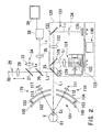
- FIG. 2 is a view schematically showing the structure of the optical systems stored in the measurement part 5.
- An optical system 101 is used to irradiate (project) light for measuring a corneal shape.
- a placido disc 102 and a reflecting plate 104 are approximately dome-shaped, and have apertures at their centers.
- On the disc 102 a pattern of rings including a multitude of light-transmitting parts and light-shielding parts is formed in concentric circles around an optical axis L1.
- a light source 103 such as an LED emits visible light, which is then reflected by the reflecting plate 104 to illuminate the placido disc 102 from behind approximately uniformly.
- An image of the ring pattern is formed on a cornea Ec of a patient's eye E.
- An anterior-segment illumination light source 105 emitting near-infrared light is provided on the rim of the placido disc 102.
- an optical system 110 used to irradiate (project) near infrared light as a target (index) for alignment in a working distance direction, which has a light source 111 and a lens 112, and an optical system 115 used to detect an image of the target, which has a lens 116 and a position-detecting element 117.
- the near-infrared light emitted from the light source 111 is changed into approximately parallel light via the lens 112.
- the light passes through the apertures provided in the reflecting plate 104 and the placido disc 102 respectively, and is then applied to the cornea Ec from an oblique direction, thereby forming the target image on the cornea Ec.
- the light of the target image formed on the cornea Ec passes through the apertures provided in the placido disc 102 and the reflecting plate 104, and enters the position-detecting element 117 via the lens 116. Based on the position of the target image light having entered the position-detecting element 117, alignment condition in the working distance direction of the apparatus with respect to the eye E is detected.
- An eye refractive power measurement optical system 120 is provided behind the reflecting plate 104.
- the eye refractive power measurement optical system 120 is composed of a slit light irradiating (projecting) optical system 121 and a slit image detecting optical system 131.
- Near infrared light emitted from a light source 122 illuminates a slit aperture provided in a rotation sector 123.
- the slit light scanned by rotation of the rotation sector 123 passes through a lens 124 and a diaphragm 125, and is then reflected by a half mirror 126. Thereafter the slit light passes through a dichroic mirror 25, converges in the vicinity of the cornea Ec, and is then irradiated (projected) onto a fundus Ef of the eye E.
- the half mirror 126 makes the optical axis L1 of the lens 124 coaxial with an optical axis L2 of a photo-receiving lens 132.
- the dichroic mirror 25 makes the optical axis L1 coaxial with an optical axis L3 of a lens 28.
- a diaphragm 134 is placed at the back focal position of the lens 132.
- a photo-receiving part 135 has a photo-receiving surface on which eight photo-receiving elements 136a to 136h are arranged in the positions approximately conjugate with the cornea Ec with respect to the lens 132.
- the photo-receiving elements 136a to 136f are positioned on a straight line passing through the center of the photo-receiving surface (the optical axis L2), and each pair of the photo-receiving elements 136a and 136b, 136c and 136d, and 136e and 136f are disposed symmetrically with respect to the center of the photo-receiving surface.
- the distance between the photo-receiving elements arranged in three pairs are set so as to obtain refractive power at the positions corresponding to those elements in a meridian direction on the cornea (each of the distances in Fig.4 is shown as an equivalent size on the cornea).
- the photo-receiving elements 136g and 136h are disposed symmetrically with respect to the center of the photo-receiving surface on a straight line perpendicular to the straight line of the photo-receiving elements 136a to 136f.
- the slit light reflected from the fundus Ef passes through the dichroic mirror 25, the half mirror 126 and the lens 132, is reflected by a mirror 133, passes through the diaphragm 134, and is then received by the photo-receiving part 135.
- a rotation mechanism 140 constituted of a motor, a gear and the like rotates the rotation sector 123 and the photo-receiving part 135 in synchronism about their respective optical axes.
- the fixation target plate 29 has a fixation point as a target (index) for eye-fixation at its center, and the periphery of that point on the plate 29 is configured to transmit visible light emitted from the light source 30.
- the light emitted from the light source 30 is irradiated (projected) onto the eye E via the plate 29, the lens 28, the half mirrors 27 and 26, and the dichroic mirror 25.
- the lens 28, which is movable in the direction of the optical axis L3 to change the position of the fixation point, fogs the eye E at the time of eye refractive power measurement, or applies accommodation load.
- a light source 34 for alignment is placed, and near infrared light as a target (index) for alignment in vertical and lateral directions is irradiated (projected) onto the cornea Ec when the light source 34 lights up.
- a CCD camera 38 as an image pickup element is placed, and the camera 38 receives the light reflected from the eye E.
- the output from the camera 38 is inputted to a monitor 39, on which a picked-up image is then displayed.
- the camera 38 is used for obtaining the anterior segment image for observation, detecting the ring pattern image, and detecting an image of the target for alignment in the vertical and lateral directions.
- the present apparatus measures a corneal shape and eye refractive power, and computes corneal ablation information (data) for refractive surgery based on the data obtained from both measurements.
- the present apparatus also computes pupil information including the position of a pupil center and the shape of the pupil in photopia and those in scotopia, and then information about differences (variances) between the pupil information in photopia and that in scotopia.
- the pupil information and/or the difference information are used as information for determining the position at which a laser beam is aligned with the eye E (information for correcting the alignment position).
- a mode-selecting switch 40 is used to select a refractive power measuring mode.
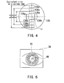
- An examiner makes the patient to gaze at the fixation point illuminated by the light source 30, and moves the measurement part 5 in the X, Y and Z directions by operating the joystick 4 and the like to performs alignment, while observing the anterior segment image of the eye E displayed on the monitor 39 shown in Fig. 5.
- the alignment in the X and Y directions is performed so that an alignment target image 61 that the light source 34 forms at an optical center defined by a corneal optical system of the eye E is positioned at the center of an aiming marker 60 (see Fig.
- the aiming marker 60 displayed on the monitor 39 may be formed electrically, and adjustments are made in advance so that the center of the aiming marker 60 may coincide with an image-pickup optical axis (measurement optical axis) of the camera 38.
- the image-pickup optical axis is made coaxial with the optical axis L5.
- a control part 50 performs control to display an indicator for working distance alignment on the monitor 39. With reference to this indicator, the examiner moves the main body 3 in the Z direction to make working distance alignment.
- the examiner depresses a measurement switch 41. Then, the measurement of eye refractive power is performed by the eye refractive power measurement optical system 120, and the anterior segment image of the eye E picked up by the camera 38 immediately before or after that measurement is stored in an image memory 43.
- An eye refractive power computation part 51 obtains a distribution of eye refractive power based on the phase difference between the output signals from each of the photo-receiving elements included in the photo-receiving part 135.
- USP 5,907,388 corresponding to Japanese Patent Application Unexamined Publication No. Hei 10-108837) should be referred to, which describes basically the same measurement.
- the anterior-segment image stored in the image memory 43 at this point is an image of the anterior segment of the eye E of which the pupil is dilated (in scotopia).
- the pupil should be wide open under the condition of natural mydriasis in a dark place where the letters in a newspaper are barely readable.
- the light intensity of the light source 30 which presents the fixation point should be adjusted for brightness so that the eye E may visually identify the fixation point, and should also be adjusted (reduced) so that myosis will not occur.
- the control part 50 adjusts the light intensity of the light source 30.
- a corneal shape measurement mode is selected using the mode-selecting switch 40.
- the examiner performs alignment in the same manner as the eye refractive power measurement while looking at the monitor 39 to observe the anterior-segment image of the eye E which is illuminated by the light source 105.
- the light source 103 is lit for a predetermined time to project light of the ring pattern onto the cornea Ec.
- the light source 30 is lit at the maximum intensity of light.
- the anterior segment image in which the ring pattern image is formed is picked up by the camera 38, and is stored in the image memory 43. Since the light from the light source 103 and that from the light source 30 are both visible, the pupil of the eye E is constricted when the light source 103 and the light source 30 light up.
- the anterior segment image in photopia may be an image in which the ring pattern image is formed.
- the light source 103 may be turned off immediately after the ring pattern image is picked up, and then the anterior segment image in photopia may be obtained separately from the image for the corneal shape measurement.
- the light source 103 is kept lighted in view of the time for the pupil to be constricted.
- the anterior segment image in photopia with the pupil constricted is stored in the image memory 43.
- the light intensity of the light sources 103 and 30 giving visible stimulating light to the eye E at this point of time is adjusted to the extent of bringing the pupil into the same myotic condition as that required to perform refractive surgery using a corneal surgery apparatus which will be described below.
- a corneal shape computation part 52 conducts image processing on the ring pattern image stored in the image memory 43, and detects the edges of the ring pattern image. Then, the corneal shape computation part 52 obtains the position of each edge relative to the corneal center for each step of a predetermined angle (1 degree), thereby obtaining a distribution of corneal curvature.
- a keyboard 58 or a mouse 57 connected to the control part 50 are operated in accordance with instructions displayed on the monitor 39 in order to input data about the size of an ablation area, a correction amount and the like.
- An ablation information computation part 54 computes corneal ablation information (data) such as an ablation amount based on the data from both the measurements and the inputted data. For more details about this computation, see USP 6,033,075 (corresponding to Japanese Patent Application Unexamined Publication No. Hei 11-342152). These measurement data and a result of the computation of the corneal ablation information are displayed on the monitor 39.
- the distribution of eye refractive power is measured, but a distribution of wave aberration may be measured instead (as disclosed in USP 6,086,204).
- the distribution of eye refractive power may be replaced with the distribution of wave aberration, meaning that both are equivalent.
- a pupil information computation part 53 conducts image processing on each of the photopic and scotopic anterior-segment images stored in the image memory 43, and thereby obtains the pupil position (the pupil center position) and the pupil shape in each of the images .
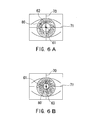
- Figs . 6A and 6B show a method by which the pupil information computation part 53 obtains the pupil center position in photopia and that in scotopia, and thus obtains the information for determining the alignment position (the information for correcting the alignment position).
- Fig. 6A shows the scotopic anterior segment image picked up at the time of the eye refractive power measurement.
- the pupil information computation part 53 detects the edge of a pupil 80 based on a distribution of light intensity in the anterior-segment image, thereby obtaining the shape of the pupil 80.
- the pupil center position may be obtained as an intersection point of two midpoints between the pupil edges, one of which is on a lateral detection line 71 and the other on a vertical detection line 70 both passing through the center of the alignment target image 61 for alignment in the vertical and lateral directions.
- Reference numeral 62 denotes the obtained pupil center position.
- the pupil information computation part 53 detects the center of the alignment target image 61, and then obtains information about the pupil center position 62 with respect to the detected center of the alignment target image 61.
- Fig. 6B shows the photopic anterior segment image.
- the pupil information computation part 53 obtains the shape of a pupil 80' based on the edge of the pupil 80'in photopia, and detects the alignment target image 61 to obtain the pupil center position 63, thereby obtaining the information about the pupil center position 63 with respect to the alignment target image 61.
- the pupil center position it is preferred to average a plurality of positional coordinates of pupil edges specified in the vicinity of the lateral and vertical detection lines intersecting at the center of the alignment target image 61.
- alternative vertical and lateral detection lines which intersect at the center of the image may be specified to obtain the pupil edges, thus obtaining the pupil center position.
- the outline of the pupil may be obtained in advance by image processing, and the pupil center position may be obtained as an intersection point of the diagonal lines of a square circumscribing that outline.
- the alignment target image 61 does not necessarily have to be detected.
- the pupil center position 62 and/or the pupil center position 63 may be obtained with respect to a predetermined position such as the center of the image. To be more specific, it is such a case where an automatic alignment mechanism is adopted.
- the pupil information computation part 53 compares the pupil center positions 62 and 63 with respect to the alignment target image 61, and obtains an amount of deviation (information about differences) of the scotopic pupil center position 62 from the photopic pupil center position 63.
- the deviation amount may be obtained as curvilinear coordinates, XY coordinates or others, of which the origin point is at the pupil center position 63.
- the deviation amount obtained is stored in a storage part 45 as the information for correcting the alignment position.
- Fig. 7 is an example of such display, where a line of the pupil edge in scotopia and that in photopia are graphically displayed based on the anterior segment image in photopia.
- a reference point for aligning them is the alignment target mark 61.
- the pupil shape (pupil diameter) in scotopia and that in photopia are numerically displayed as well as the information about the distance between the scotopic and photopic pupil center positions.
- the information about the scotopic and photopic pupil diameters may be utilized to determine the size of the ablation area.
- the stored information is outputted through a communication port 59b or a floppy disc inserted in a floppy-disc drive 59a, and is then inputted to a computer included in a corneal surgery apparatus 200.
- a mechanism of the refractive power measurement and that of the corneal shape measurement may be implemented individually in two separate ophthalmic apparatuses.
- a mechanism of picking up the anterior segment image in scotopia and a mechanism of picking up that in photopia may also be implemented individually in two separate ophthalmic apparatuses.
- the computation of the corneal ablation information based on the measurement data and the pupil information by image processing may be conducted using a personal computer (the ophthalmic apparatus having the ablation information computation part 54, the pupil information computation part 53, input means such as the mouse 57, the keyboard 58, the communication port 59b and the FDD 59a, output means such as the communication port 59b and the FDD 59a and the monitor 39, and others shown in Fig. 3).
- the measurement data and the anterior segment images picked up in photopia and scotopia are inputted to the personal computer, which displays (outputs) the computation result on (to) the monitor 39.
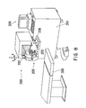
- Fig. 8 is a schematic external view of the corneal surgery apparatus 200
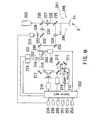
- Fig. 9 shows the structure of its optical system.
- the laser beam from an excimer laser light source 210 placed inside a surgery apparatus main body 201 passes through a laser irradiation optical system including mirrors and the like, and is directed to an arm unit 202 which is movable in X and Y directions shown in Fig. 8.
- An arm-tip portion 205 is movable in a Z direction.
- Driving units 251, 252 and 253 constituted of motors and the like bring about movements in those directions.
- a controller 206 includes a joystick and a variety of switches.
- a computer 209 is capable of inputting various data about conditions required for surgery as well as computing, displaying and storing data about laser irradiation control. On a bed 300 for a patient, the patient undergoes surgery while he is lying down on the bed 300.
- the laser irradiation optical system includes mirrors 211 and 212, a scan mirror 213 (a plane mirror which translates (moves) the laser beam in the direction of the Gaussian distribution), an image rotator 215, a mirror 217, a variable circular aperture 218, a variable slit aperture 220, mirrors 222 and 223, a projecting lens 224, and a dichroic mirror 225.
- a dividing aperture plate 260 having a plurality of small circular apertures is placed on an optical path between the slit aperture 220 and the mirror 222, and is configured to be removable from and insertable into the optical path.
- the dividing aperture plate 260 is configured to selectively divide the laser beam in combination of a dividing shutter 265.
- the small circular apertures of the dividing aperture plate 260 are selectively covered and uncovered by shutter plates of the dividing shutter 265. This enables selective division of the rectangle-shaped laser beam in the longitudinal direction during the laser irradiation.
- the dividing aperture plate 260 and the dividing shutter 265 may be moved in a plane normal to the axis of the laser beam by the driving unit 268.
- a fixation lamp 226, an objective lens 227, and a microscope unit 203 are placed above the dichroic mirror 225.
- a visible light source 247 illuminates the eye E, and a surgeon observes the eye E through the microscope unit 203.
- a mirror 230 is placed between binocular optical paths of the microscope unit 203 (on an optical axis of the objective lens 227).
- an image-forming lens 231, a mirror 232, an infrared light transmission filter 235 and a CCD camera 233 are arranged in the order in which they are mentioned above.
- the camera 233 picks up the anterior segment image of the eye E illuminated by an infrared light source 246.
- the output of the camera 233 is connected to an image processing part 234.
- Reference letter L 0 indicates a reference axis of irradiation of the laser beam.
- One of the switches included in the controller 206 is operated to select an automatic alignment mode and/or an automatic tracking mode.
- the image processing part 234 conducts the same process as shown in Figs. 6A and 6B based on the anterior segment image picked up by the camera 233, thereby obtaining (detecting) the pupil center position of the eye E.
- the eye E is in photopia since the corneal surgery apparatus 200 is used in a well-lighted room and the eye E is illuminated by the visible illumination light source 247. Therefore, the pupil center position obtained at the time of surgery is the pupil center position in photopia.
- a control part 250 performs alignment by controlling movement of the arm unit 202 relative to the obtained pupil center position.
- the control part 250 offsets the reference axis L 0 of irradiation with respect to the pupil center position so that the reference axis L may be aligned with the pupil center position in scotopia.
- the control part 250 controls driving units 214, 216, 219 and 221, the driving unit 268 and others for the scan mirror 213, the image rotator 215, the variable circular aperture 218, the variable slit aperture 220, the dividing aperture plate 260, the dividing shutter 265, respectively, thereby irradiating the eye E with the laser beam. If the eye E moves, the arm unit 202 is moved based on the obtained pupil center position, whereby automatic tracking is performed.
- the alignment position of the laser beam is offset from the pupil center position in photopia to the pupil center position in scotopia. This makes it possible to ablate an area predetermined based on the scotopic pupil center position. Therefore, such ablation may prevent a halo, glare or the like, which is apt to occur at night after surgery, with more reliability than the ablation in alignment with the photopic pupil center position.
- the eye E rotates since the refractive surgery is conducted as the patient is lying down (on his back). Accordingly, ablation may be performed more accurately if information about the rotation (torsion) of the eye E which occurs when the patient lies on his back (rotation angle information) is added to the corneal ablation information for the same eye E which is obtained when he is seated.
- the surgeon obtains an angle of the eye rotation in advance based on the conditions of the eye E when the patient is seated and when he is lying down on his back, and this information is then inputted to the computer 209.
- the description of the present embodiment implies that an inclination of the patient's head at the time of image-pickup may be ignored in the anterior segment image in photopia and that in scotopia.
- the aforementioned method for extracting the characteristics of the anterior segment images is followed, so that the anterior segment image in photopia and that in scotopia are corrected for the inclination, and a series of procedures may be executed thereafter.
- the anterior segment image in scotopia is picked up at the time of eye refractive power measurement, and the anterior segment image in photopia is picked up at the time of corneal shape measurement, but the present invention is not limited thereto.
- the apparatus may be configured to have alternative modes of picking up the anterior segment images, one of which is specific for photopia and the other for scotopia to be selected using the mode-selecting switch 40.
- the light intensity of the light source 30 for eye-fixation is reduced within a range that allows the patient to gaze at the fixation point, while the light source 103 for corneal shape measurement is switched off, and thus the pupil of the eye E may be dilated.
- the light intensity of the light source 103 and that of the light source 30 may be set to cause myosis in the same degree as that in refractive surgery.
- the visible light source is not limited to the light sources 103 and 30.
- the light source 103 may be a near infrared light source, and another light source may be provided as a visible light source instead.
- the alignment target image 61 on the cornea Ec is aligned with the image-pickup axis when the anterior segment image is picked up, but the present invention is not limited thereto; it is also possible to use a method by which the image-pickup axis is aligned with the pupil center position when the anterior segment image is picked up.
- a description will be given to a method for obtaining the information for correcting the alignment position under the method by which the image-pickup axis is aligned with the pupil center position at the time of picking up the image.
- the ophthalmic apparatus adopted in the aforementioned embodiment is used.
- the image-pickup axis is aligned with the scotopic pupil center position displayed on the monitor 39 through visual observations, and the anterior segment image is then picked up.
- the pupil information computation part 53 detects boundaries of the cornea Ec (a corneal outline) by conducting image processing on the picked-up anterior segment image in scotopia, and obtains the central coordinates of the corneal boundaries.
- the pupil information computation part 53 obtains the scotopic pupil center position in the picked-up image by the same method as in the aforementioned embodiment.
- the pupil information computation part 53 computes the scotopic pupil center position witch respect to the central coordinates calculated from the corneal outline.
- the anterior segment image in photopia is picked up, and the photopic pupil center position is obtained with respect to the central coordinates calculated from the corneal outline by the same method.
- the center of the corneal outline obtained from the anterior segment image of the scotopic eye is made to coincide with that of the photopic eye, thereby computing the distance between the scotopic and photopic pupil center positions.
- the distance thus obtained may be used as the information for correcting the alignment position in the same manner as in the aforementioned embodiment.
- the present embodiment has been described taking the ophthalmic apparatus capable of measuring both eye refractive power and a corneal shape as an example, but the present invention is not limited thereto. Any other ophthalmic apparatus may be used as long as it is capable of obtaining pupil information in scotopia and that in photopia.
- the present invention allows not only obtaining the information about the pupil position, but also obtaining the pupil diameter (pupil shape) in scotopia and that in photopia.
- the obtained pupil diameters may therefore be used for designing a contact lens or other purposes.
Landscapes
- Health & Medical Sciences (AREA)
- Life Sciences & Earth Sciences (AREA)
- Ophthalmology & Optometry (AREA)
- Surgery (AREA)
- General Health & Medical Sciences (AREA)
- Physics & Mathematics (AREA)
- Engineering & Computer Science (AREA)
- Biomedical Technology (AREA)
- Heart & Thoracic Surgery (AREA)
- Veterinary Medicine (AREA)
- Public Health (AREA)
- Animal Behavior & Ethology (AREA)
- Nuclear Medicine, Radiotherapy & Molecular Imaging (AREA)
- Optics & Photonics (AREA)
- Vascular Medicine (AREA)
- Biophysics (AREA)
- Medical Informatics (AREA)
- Molecular Biology (AREA)
- Eye Examination Apparatus (AREA)
- Laser Surgery Devices (AREA)
- Radiation-Therapy Devices (AREA)
Description
- The present invention relates to an ophthalmic apparatus used in ophthalmic clinics and the like.
- On ophthalmic diagnosis, examination, treatment and prescription, it is sometimes necessary to obtain information about the position and/or shape of a pupil. For example, in corneal surgery for correcting refractive power by ablating a cornea with a laser beam, it is common practice to align a reference axis of irradiation of the laser beam with the position of a pupil center.
- In addition, among multifocal contact lenses, in which different lens diopters are provided in the form of concentric circles around an axis of an optical center of the lens, there are some in which the axis of the optical center is decentered with respect to the geometric center of the lens. The amount of the decentering is determined in consideration of the pupil center position.
- By the way, in the above-mentioned corneal surgery, a surgeon performs surgery in a well-lighted surgery room while observing a patient's eye illuminated with visible light. In this case, the patient's eye is in photopia (photopic vision) (i.e. the pupil of the eye is constricted), and the laser-beam irradiation is performed in alignment with the pupil center position in photopia. However, there are some cases where the pupil center position in photopia is not necessarily equal to that in scotopia (i.e. the pupil of the eye is dilated), according to individual circumstances. Conventionally, the differences (variances) between the pupil center position in photopia and that in scotopia are not taken into account. Therefore, the laser irradiation based on the pupil center position of the eye in photopia tends to cause a halo or glare when the eye is in scotopia.
- Also, when designing a multifocal contact lens as described above, it has not been taken into account that the pupil center position in photopia is different from that in scotopia.
- EP-A-0850614 discloses an ophthalmic operating apparatus for performing a treatment onto a patient's eye by use of a laser beam. This apparatus comprises optical systems for observing an anterior part of the patient's eye by irradiating a visible light and a near-infrared light beam on the patient's eye, and an image processing means for obtaining a position of a pupil center based on an image detected by means of the near-infrared light beam, so that it is possible to track the movement of the patient's eye during the laser beam irradiation operation.
- The present invention has been made in view of the above circumstances and has an object to overcome the above problems and to provide an ophthalmic apparatus capable of obtaining information about the differences between the pupil information in photopia and that in scotopia with unerring accuracy.
- Additional objects and advantages of the invention will be set forth in part in the description which follows and in part will be obvious from the description, or may be learned by practice of the invention. The objects and advantages of the invention may be realized and attained by means of the instrumentalities and combinations particularly pointed out in the appended claims.
- To achieve the objects and in accordance with the purpose of the present invention, as embodied and broadly described herein, an ophthalmic apparatus comprises input means for inputting a first image of an anterior segment of a patient's eye in photopia and a second image of the anterior segment of the eye in scotopia, a pupil information computation unit which obtains, by image processing, pupil information including at least one of a position of a pupil of the eye and a shape of the pupil in each of the inputted images, and obtains information about a difference between the pupil information in the first image and that in the second image, and output means for outputting the obtained information about the difference, wherein, the pupil information computation means obtains a position of a pupil center of the eye in each of the inputted images, and obtains information about a positional difference between the pupil center position in the first image and the pupil center position in the second image; and the output means outputs the obtained information about the positional difference.
- The information about the differences obtained with the ophthalmic apparatus according to the present invention can be used with a corneal surgery apparatus for ablating a cornea by laser beam irradiation comprising a laser irradiation unit which irradiates a cornea of a patient's eye with a laser beam, the irradiation unit including an optical system, an alignment unit which aligns an irradiation position of the laser beam with the eye, position input means for inputting information about a positional difference between a pupil position of the eye in photopia and a pupil position of the eye in scotopia, a pupil position detection unit which detects a pupil position of the eye in photopia by image processing, the pupil position detection unit including an image pickup element which obtains an image of the eye in photopia through image-pickup, a position computation unit which obtains information about an alignment position of the laser beam based on the detected pupil position and the inputted information about the positional difference, and an alignment control unit which controls the alignment unit based on the obtained information about the alignment position.
- According to the present invention described above, the information about the differences between pupil information in photopia and that in scotopia may be obtained with unerring accuracy. The pupil information and/or the information about the differences thus obtained may therefore be utilized for refractive surgery and design of a contact lens.
- The accompanying drawings, which are incorporated in and constitute a part of this specification, illustrate embodiments of the present invention and, together with the description, serve to explain the objects, advantages and principles of the invention. In the drawings,
- Figs. 1A and 1B are views schematically showing an external configuration of an ophthalmic apparatus consistent with the present invention;
- Fig. 2 is a view schematically showing a structure of an optical system included in the ophthalmic apparatus;
- Fig. 3 is a block diagram schematically showing a control system included in the ophthalmic apparatus;
- Fig. 4 is a view showing an arrangement of photo-receiving elements;
- Fig. 5 is a view showing a method for performing alignment using an image of an anterior segment of an eye displayed on a monitor;
- Figs. 6A and 6B are views showing a method for obtaining the position of the pupil center from the picked-up image of the anterior segment of the eye;
- Fig. 7 is a view showing an example of displaying a difference between the pupil center position in photopia and that in scotopia;
- Fig. 8 is a view schematically showing an external configuration of a corneal surgery apparatus; and
- Fig. 9 is a view schematically showing a structure of an optical system included in the corneal surgery apparatus.
- A detailed description of one preferred embodiment of an ophthalmic apparatus embodying the present invention and of a corneal surgery apparatus will now be given referring to the accompanying drawings. Figs. 1A and 1B are views schematically showing an external configuration of the ophthalmic apparatus consistent with the present invention; Fig. 1A is a front view seen from an examinee's side, and Fig. 1B is a side view.
- On a
fixation base 1, ahead supporting part 2 is mounted securely in order to fix the examinee's head. In ameasurement part 5, optical systems and other systems are stored. Ameasurement window 5a through which light passes is provided approximately at the lateral center on the side facing the examinee. When ajoystick 4 is tilted backward/forward and rightward/leftward, amain body 3 incorporating themeasurement part 5 slides and moves backward/forward and rightward/leftward (in Z and X directions) on thefixation base 1. In addition, when arotation knob 4a provided on thejoystick 4 is rotated, a Y(up-and-down)-direction driving device constituted of a motor and the like is actuated to move themeasurement part 5 up and down (in a Y direction) with respect to themain body 3. - On a
color monitor 39, an image of an anterior segment of a patient's eye is displayed for observation, along with alignment information, a measurement result, and other information to be indicated to an examiner. - Fig. 2 is a view schematically showing the structure of the optical systems stored in the
measurement part 5. Anoptical system 101 is used to irradiate (project) light for measuring a corneal shape. Aplacido disc 102 and areflecting plate 104 are approximately dome-shaped, and have apertures at their centers. On thedisc 102, a pattern of rings including a multitude of light-transmitting parts and light-shielding parts is formed in concentric circles around an optical axis L1. Alight source 103 such as an LED emits visible light, which is then reflected by the reflectingplate 104 to illuminate theplacido disc 102 from behind approximately uniformly. An image of the ring pattern is formed on a cornea Ec of a patient's eye E. An anterior-segmentillumination light source 105 emitting near-infrared light is provided on the rim of theplacido disc 102. - Placed behind the reflecting
plate 104 are anoptical system 110 used to irradiate (project) near infrared light as a target (index) for alignment in a working distance direction, which has alight source 111 and alens 112, and anoptical system 115 used to detect an image of the target, which has alens 116 and a position-detectingelement 117. The near-infrared light emitted from thelight source 111 is changed into approximately parallel light via thelens 112. The light passes through the apertures provided in thereflecting plate 104 and theplacido disc 102 respectively, and is then applied to the cornea Ec from an oblique direction, thereby forming the target image on the cornea Ec. The light of the target image formed on the cornea Ec passes through the apertures provided in theplacido disc 102 and thereflecting plate 104, and enters the position-detectingelement 117 via thelens 116. Based on the position of the target image light having entered the position-detectingelement 117, alignment condition in the working distance direction of the apparatus with respect to the eye E is detected. - An eye refractive power measurement
optical system 120 is provided behind the reflectingplate 104. The eye refractive power measurementoptical system 120 is composed of a slit light irradiating (projecting)optical system 121 and a slit image detectingoptical system 131. Near infrared light emitted from alight source 122 illuminates a slit aperture provided in arotation sector 123. The slit light scanned by rotation of therotation sector 123 passes through alens 124 and adiaphragm 125, and is then reflected by ahalf mirror 126. Thereafter the slit light passes through adichroic mirror 25, converges in the vicinity of the cornea Ec, and is then irradiated (projected) onto a fundus Ef of the eye E. - The
half mirror 126 makes the optical axis L1 of thelens 124 coaxial with an optical axis L2 of a photo-receivinglens 132. Thedichroic mirror 25 makes the optical axis L1 coaxial with an optical axis L3 of alens 28. - A
diaphragm 134 is placed at the back focal position of thelens 132. A photo-receivingpart 135 has a photo-receiving surface on which eight photo-receivingelements 136a to 136h are arranged in the positions approximately conjugate with the cornea Ec with respect to thelens 132. Among them, the photo-receivingelements 136a to 136f are positioned on a straight line passing through the center of the photo-receiving surface (the optical axis L2), and each pair of the photo-receivingelements elements elements 136a to 136f. - The slit light reflected from the fundus Ef passes through the
dichroic mirror 25, thehalf mirror 126 and thelens 132, is reflected by amirror 133, passes through thediaphragm 134, and is then received by the photo-receivingpart 135. - In the eye refractive power measurement
optical system 120, arotation mechanism 140 constituted of a motor, a gear and the like rotates therotation sector 123 and the photo-receivingpart 135 in synchronism about their respective optical axes. - On the optical axis L3, half mirrors 26 and 27, a a fixation target plate 29, and a
light source 30 for eye-fixation are placed. The fixation target plate 29 has a fixation point as a target (index) for eye-fixation at its center, and the periphery of that point on the plate 29 is configured to transmit visible light emitted from thelight source 30. The light emitted from thelight source 30 is irradiated (projected) onto the eye E via the plate 29, thelens 28, the half mirrors 27 and 26, and thedichroic mirror 25. Thelens 28, which is movable in the direction of the optical axis L3 to change the position of the fixation point, fogs the eye E at the time of eye refractive power measurement, or applies accommodation load. - On an optical axis L4 of a
lens 33 made coaxial with the optical axis L3 by thehalf mirror 27, alight source 34 for alignment is placed, and near infrared light as a target (index) for alignment in vertical and lateral directions is irradiated (projected) onto the cornea Ec when thelight source 34 lights up. - In addition, on an optical axis L5 of a
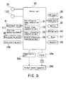
lens 35 made coaxial with the optical axis L3 by thehalf mirror 26, aCCD camera 38 as an image pickup element is placed, and thecamera 38 receives the light reflected from the eye E. The output from thecamera 38 is inputted to amonitor 39, on which a picked-up image is then displayed. Thecamera 38 is used for obtaining the anterior segment image for observation, detecting the ring pattern image, and detecting an image of the target for alignment in the vertical and lateral directions. - Next, the operation of the apparatus will now be described referring to a block diagram schematically showing a control system shown in Fig. 3. The present apparatus measures a corneal shape and eye refractive power, and computes corneal ablation information (data) for refractive surgery based on the data obtained from both measurements. In addition, the present apparatus also computes pupil information including the position of a pupil center and the shape of the pupil in photopia and those in scotopia, and then information about differences (variances) between the pupil information in photopia and that in scotopia. When ablation is performed using a corneal surgery apparatus, the pupil information and/or the difference information are used as information for determining the position at which a laser beam is aligned with the eye E (information for correcting the alignment position).
- First, the operation performed at the time of eye refractive power measurement will now be described. A mode-selecting
switch 40 is used to select a refractive power measuring mode. - An examiner makes the patient to gaze at the fixation point illuminated by the
light source 30, and moves themeasurement part 5 in the X, Y and Z directions by operating thejoystick 4 and the like to performs alignment, while observing the anterior segment image of the eye E displayed on themonitor 39 shown in Fig. 5. The alignment in the X and Y directions is performed so that analignment target image 61 that thelight source 34 forms at an optical center defined by a corneal optical system of the eye E is positioned at the center of an aiming marker 60 (see Fig. 5) displayed on the monitor 39 (hereinafter, the above-mentioned optical center will be referred to as a corneal center of the eye E, but it can be regarded as approximately a center of a visual axis of the eye E.) The aimingmarker 60 displayed on themonitor 39 may be formed electrically, and adjustments are made in advance so that the center of the aimingmarker 60 may coincide with an image-pickup optical axis (measurement optical axis) of thecamera 38. The image-pickup optical axis is made coaxial with the optical axis L5. For the alignment in the Z direction, based on information about deviation in the working distance direction, which is obtained by the position-detectingelement 117, acontrol part 50 performs control to display an indicator for working distance alignment on themonitor 39. With reference to this indicator, the examiner moves themain body 3 in the Z direction to make working distance alignment. - Once the alignment has been completed, the examiner depresses a
measurement switch 41. Then, the measurement of eye refractive power is performed by the eye refractive power measurementoptical system 120, and the anterior segment image of the eye E picked up by thecamera 38 immediately before or after that measurement is stored in animage memory 43. An eye refractivepower computation part 51 obtains a distribution of eye refractive power based on the phase difference between the output signals from each of the photo-receiving elements included in the photo-receivingpart 135. For more details about the measurement of an eye refractive power distribution, USP 5,907,388 (corresponding to Japanese Patent Application Unexamined Publication No. Hei 10-108837) should be referred to, which describes basically the same measurement. - The anterior-segment image stored in the
image memory 43 at this point is an image of the anterior segment of the eye E of which the pupil is dilated (in scotopia). During the measurement of eye refractive power, in order to obtain a refractive power distribution of wide range, it is preferred that the pupil should be wide open under the condition of natural mydriasis in a dark place where the letters in a newspaper are barely readable. In addition, the light intensity of thelight source 30 which presents the fixation point should be adjusted for brightness so that the eye E may visually identify the fixation point, and should also be adjusted (reduced) so that myosis will not occur. Thecontrol part 50 adjusts the light intensity of thelight source 30. - Next, a description will be given to the operation performed at the time of corneal shape measurement. Prior to the measurement, a corneal shape measurement mode is selected using the mode-selecting
switch 40. The examiner performs alignment in the same manner as the eye refractive power measurement while looking at themonitor 39 to observe the anterior-segment image of the eye E which is illuminated by thelight source 105. - After completion of the alignment, when the
measurement switch 41 is depressed, thelight source 103 is lit for a predetermined time to project light of the ring pattern onto the cornea Ec. Here, thelight source 30 is lit at the maximum intensity of light. The anterior segment image in which the ring pattern image is formed is picked up by thecamera 38, and is stored in theimage memory 43. Since the light from thelight source 103 and that from thelight source 30 are both visible, the pupil of the eye E is constricted when thelight source 103 and thelight source 30 light up. The anterior segment image in photopia may be an image in which the ring pattern image is formed. However, thelight source 103 may be turned off immediately after the ring pattern image is picked up, and then the anterior segment image in photopia may be obtained separately from the image for the corneal shape measurement. Thelight source 103 is kept lighted in view of the time for the pupil to be constricted. The anterior segment image in photopia with the pupil constricted is stored in theimage memory 43. - It should be noted that, preferably, the light intensity of the
light sources - A corneal
shape computation part 52 conducts image processing on the ring pattern image stored in theimage memory 43, and detects the edges of the ring pattern image. Then, the cornealshape computation part 52 obtains the position of each edge relative to the corneal center for each step of a predetermined angle (1 degree), thereby obtaining a distribution of corneal curvature. - Once the data have been obtained from the measurements of the distributions of eye refractive power and corneal curvature both concerning the same eye E, a
keyboard 58 or a mouse 57 connected to thecontrol part 50 are operated in accordance with instructions displayed on themonitor 39 in order to input data about the size of an ablation area, a correction amount and the like. An ablationinformation computation part 54 computes corneal ablation information (data) such as an ablation amount based on the data from both the measurements and the inputted data. For more details about this computation, see USP 6,033,075 (corresponding to Japanese Patent Application Unexamined Publication No. Hei 11-342152). These measurement data and a result of the computation of the corneal ablation information are displayed on themonitor 39. - In the foregoing description, the distribution of eye refractive power is measured, but a distribution of wave aberration may be measured instead (as disclosed in USP 6,086,204). The distribution of eye refractive power may be replaced with the distribution of wave aberration, meaning that both are equivalent.
- In addition, once the anterior segment image in photopia and that in scotopia are both obtained, a pupil
information computation part 53 conducts image processing on each of the photopic and scotopic anterior-segment images stored in theimage memory 43, and thereby obtains the pupil position (the pupil center position) and the pupil shape in each of the images . Figs . 6A and 6B show a method by which the pupilinformation computation part 53 obtains the pupil center position in photopia and that in scotopia, and thus obtains the information for determining the alignment position (the information for correcting the alignment position). - Fig. 6A shows the scotopic anterior segment image picked up at the time of the eye refractive power measurement. The pupil
information computation part 53 detects the edge of apupil 80 based on a distribution of light intensity in the anterior-segment image, thereby obtaining the shape of thepupil 80. In addition, the pupil center position may be obtained as an intersection point of two midpoints between the pupil edges, one of which is on alateral detection line 71 and the other on avertical detection line 70 both passing through the center of thealignment target image 61 for alignment in the vertical and lateral directions.Reference numeral 62 denotes the obtained pupil center position. The pupilinformation computation part 53 detects the center of thealignment target image 61, and then obtains information about thepupil center position 62 with respect to the detected center of thealignment target image 61. - Fig. 6B shows the photopic anterior segment image. In a like matter, the pupil
information computation part 53 obtains the shape of a pupil 80' based on the edge of the pupil 80'in photopia, and detects thealignment target image 61 to obtain thepupil center position 63, thereby obtaining the information about thepupil center position 63 with respect to thealignment target image 61. - Incidentally, for the detection of the pupil center position, it is preferred to average a plurality of positional coordinates of pupil edges specified in the vicinity of the lateral and vertical detection lines intersecting at the center of the
alignment target image 61. In addition, alternative vertical and lateral detection lines which intersect at the center of the image may be specified to obtain the pupil edges, thus obtaining the pupil center position. Alternatively, the outline of the pupil may be obtained in advance by image processing, and the pupil center position may be obtained as an intersection point of the diagonal lines of a square circumscribing that outline. - In addition, when the corneal center of the eye E is completely aligned with the image-pickup optical axis, if both purely coincide with each other, the
alignment target image 61 does not necessarily have to be detected. In this case, thepupil center position 62 and/or thepupil center position 63 may be obtained with respect to a predetermined position such as the center of the image. To be more specific, it is such a case where an automatic alignment mechanism is adopted. - Next, the pupil
information computation part 53 compares the pupil center positions 62 and 63 with respect to thealignment target image 61, and obtains an amount of deviation (information about differences) of the scotopicpupil center position 62 from the photopicpupil center position 63. The deviation amount may be obtained as curvilinear coordinates, XY coordinates or others, of which the origin point is at thepupil center position 63. The deviation amount obtained is stored in astorage part 45 as the information for correcting the alignment position. - In addition, information about the pupil in scotopia and that in photopia is displayed on the
monitor 39. In other words, at this point, the pupil center positions 62 and 63 and/or the pupil edge in scotopia and that in photopia are graphically displayed on themonitor 39 to visually indicate the differences (variances) between the pupil center position and pupil shape in scotopia and those in photopia. Fig. 7 is an example of such display, where a line of the pupil edge in scotopia and that in photopia are graphically displayed based on the anterior segment image in photopia. A reference point for aligning them is thealignment target mark 61. Further, the pupil shape (pupil diameter) in scotopia and that in photopia are numerically displayed as well as the information about the distance between the scotopic and photopic pupil center positions. The information about the scotopic and photopic pupil diameters may be utilized to determine the size of the ablation area. - The information thus obtained about the pupil in photopia and that in scotopia, and also about the differences between them, is stored in the
storage part 45 along with the corneal ablation information. The stored information is outputted through acommunication port 59b or a floppy disc inserted in a floppy-disc drive 59a, and is then inputted to a computer included in acorneal surgery apparatus 200. - Incidentally, a mechanism of the refractive power measurement and that of the corneal shape measurement may be implemented individually in two separate ophthalmic apparatuses. Similarly, a mechanism of picking up the anterior segment image in scotopia and a mechanism of picking up that in photopia may also be implemented individually in two separate ophthalmic apparatuses. In addition, in such cases, the computation of the corneal ablation information based on the measurement data and the pupil information by image processing may be conducted using a personal computer (the ophthalmic apparatus having the ablation
information computation part 54, the pupilinformation computation part 53, input means such as the mouse 57, thekeyboard 58, thecommunication port 59b and theFDD 59a, output means such as thecommunication port 59b and theFDD 59a and themonitor 39, and others shown in Fig. 3). The measurement data and the anterior segment images picked up in photopia and scotopia are inputted to the personal computer, which displays (outputs) the computation result on (to) themonitor 39. - Next, the
corneal surgery apparatus 200 will be described. Fig. 8 is a schematic external view of thecorneal surgery apparatus 200, and Fig. 9 shows the structure of its optical system. - The laser beam from an excimer
laser light source 210 placed inside a surgery apparatusmain body 201 passes through a laser irradiation optical system including mirrors and the like, and is directed to anarm unit 202 which is movable in X and Y directions shown in Fig. 8. An arm-tip portion 205 is movable in a Z direction. Driving units 251, 252 and 253 constituted of motors and the like bring about movements in those directions. Acontroller 206 includes a joystick and a variety of switches. Acomputer 209 is capable of inputting various data about conditions required for surgery as well as computing, displaying and storing data about laser irradiation control. On abed 300 for a patient, the patient undergoes surgery while he is lying down on thebed 300. - The laser irradiation optical system includes
mirrors image rotator 215, amirror 217, a variable circular aperture 218, avariable slit aperture 220, mirrors 222 and 223, a projectinglens 224, and adichroic mirror 225. A dividingaperture plate 260 having a plurality of small circular apertures is placed on an optical path between theslit aperture 220 and themirror 222, and is configured to be removable from and insertable into the optical path. The dividingaperture plate 260 is configured to selectively divide the laser beam in combination of a dividingshutter 265. The small circular apertures of the dividingaperture plate 260 are selectively covered and uncovered by shutter plates of the dividingshutter 265. This enables selective division of the rectangle-shaped laser beam in the longitudinal direction during the laser irradiation. The dividingaperture plate 260 and the dividingshutter 265 may be moved in a plane normal to the axis of the laser beam by the drivingunit 268. - placed above the
dichroic mirror 225 are afixation lamp 226, anobjective lens 227, and amicroscope unit 203. A visiblelight source 247 illuminates the eye E, and a surgeon observes the eye E through themicroscope unit 203. Amirror 230 is placed between binocular optical paths of the microscope unit 203 (on an optical axis of the objective lens 227). On an optical path on the reflecting side of themirror 230, an image-forminglens 231, amirror 232, an infraredlight transmission filter 235 and aCCD camera 233 are arranged in the order in which they are mentioned above. Thecamera 233 picks up the anterior segment image of the eye E illuminated by an infraredlight source 246. The output of thecamera 233 is connected to animage processing part 234. Reference letter L0 indicates a reference axis of irradiation of the laser beam. - One of the switches included in the
controller 206 is operated to select an automatic alignment mode and/or an automatic tracking mode. Theimage processing part 234 conducts the same process as shown in Figs. 6A and 6B based on the anterior segment image picked up by thecamera 233, thereby obtaining (detecting) the pupil center position of the eye E. The eye E is in photopia since thecorneal surgery apparatus 200 is used in a well-lighted room and the eye E is illuminated by the visible illuminationlight source 247. Therefore, the pupil center position obtained at the time of surgery is the pupil center position in photopia. Acontrol part 250 performs alignment by controlling movement of thearm unit 202 relative to the obtained pupil center position. At this point, based on the information for correcting the alignment position inputted to thecomputer 209, thecontrol part 250 offsets the reference axis L0 of irradiation with respect to the pupil center position so that the reference axis L may be aligned with the pupil center position in scotopia. Based on the corneal ablation information, thecontrol part 250controls driving units unit 268 and others for thescan mirror 213, theimage rotator 215, the variable circular aperture 218, thevariable slit aperture 220, the dividingaperture plate 260, the dividingshutter 265, respectively, thereby irradiating the eye E with the laser beam. If the eye E moves, thearm unit 202 is moved based on the obtained pupil center position, whereby automatic tracking is performed. - Thus, the alignment position of the laser beam is offset from the pupil center position in photopia to the pupil center position in scotopia. This makes it possible to ablate an area predetermined based on the scotopic pupil center position. Therefore, such ablation may prevent a halo, glare or the like, which is apt to occur at night after surgery, with more reliability than the ablation in alignment with the photopic pupil center position.
- In addition, the eye E rotates since the refractive surgery is conducted as the patient is lying down (on his back). Accordingly, ablation may be performed more accurately if information about the rotation (torsion) of the eye E which occurs when the patient lies on his back (rotation angle information) is added to the corneal ablation information for the same eye E which is obtained when he is seated. The surgeon obtains an angle of the eye rotation in advance based on the conditions of the eye E when the patient is seated and when he is lying down on his back, and this information is then inputted to the
computer 209. Alternatively, it is also possible to extract characteristics of the anterior segment image which is picked up when the patient is seated, and then, to compare it with the anterior segment image picked up when he is lying down on his back, thereby obtaining the rotation angle of the eye E. The description of the present embodiment implies that an inclination of the patient's head at the time of image-pickup may be ignored in the anterior segment image in photopia and that in scotopia. However, if it is desired to compensate for the inclination, the aforementioned method for extracting the characteristics of the anterior segment images is followed, so that the anterior segment image in photopia and that in scotopia are corrected for the inclination, and a series of procedures may be executed thereafter. - Further, in the present embodiment, the anterior segment image in scotopia is picked up at the time of eye refractive power measurement, and the anterior segment image in photopia is picked up at the time of corneal shape measurement, but the present invention is not limited thereto. For example, the apparatus may be configured to have alternative modes of picking up the anterior segment images, one of which is specific for photopia and the other for scotopia to be selected using the mode-selecting
switch 40. - A description will now be given to the case of providing the alternative modes specific for picking up the anterior segment images. For instance, in the image-pickup mode for scotopia, the light intensity of the
light source 30 for eye-fixation is reduced within a range that allows the patient to gaze at the fixation point, while thelight source 103 for corneal shape measurement is switched off, and thus the pupil of the eye E may be dilated. On the other hand, in the image-pickup mode for photopia, the light intensity of thelight source 103 and that of thelight source 30 may be set to cause myosis in the same degree as that in refractive surgery. It should be noted that the visible light source is not limited to thelight sources light source 103 may be a near infrared light source, and another light source may be provided as a visible light source instead. - Furthermore, in the present embodiment, the
alignment target image 61 on the cornea Ec is aligned with the image-pickup axis when the anterior segment image is picked up, but the present invention is not limited thereto; it is also possible to use a method by which the image-pickup axis is aligned with the pupil center position when the anterior segment image is picked up. Hereinafter, a description will be given to a method for obtaining the information for correcting the alignment position under the method by which the image-pickup axis is aligned with the pupil center position at the time of picking up the image. Here, it is assumed that the ophthalmic apparatus adopted in the aforementioned embodiment is used. - First, the image-pickup axis is aligned with the scotopic pupil center position displayed on the
monitor 39 through visual observations, and the anterior segment image is then picked up. The pupilinformation computation part 53 detects boundaries of the cornea Ec (a corneal outline) by conducting image processing on the picked-up anterior segment image in scotopia, and obtains the central coordinates of the corneal boundaries. Next, the pupilinformation computation part 53 obtains the scotopic pupil center position in the picked-up image by the same method as in the aforementioned embodiment. At this point, the pupilinformation computation part 53 computes the scotopic pupil center position witch respect to the central coordinates calculated from the corneal outline. - Next, the anterior segment image in photopia is picked up, and the photopic pupil center position is obtained with respect to the central coordinates calculated from the corneal outline by the same method. The center of the corneal outline obtained from the anterior segment image of the scotopic eye is made to coincide with that of the photopic eye, thereby computing the distance between the scotopic and photopic pupil center positions. The distance thus obtained may be used as the information for correcting the alignment position in the same manner as in the aforementioned embodiment.
- Moreover, the present embodiment has been described taking the ophthalmic apparatus capable of measuring both eye refractive power and a corneal shape as an example, but the present invention is not limited thereto. Any other ophthalmic apparatus may be used as long as it is capable of obtaining pupil information in scotopia and that in photopia.
- What is more, the present invention allows not only obtaining the information about the pupil position, but also obtaining the pupil diameter (pupil shape) in scotopia and that in photopia. The obtained pupil diameters may therefore be used for designing a contact lens or other purposes. For example, take a multifocal contact lens in which curved surfaces having diopters for far vision and those having diopters for near vision are formed alternately in concentric circles around the lens geometric center; such a lens may be designed to have its optical center deviated from the lens geometric center in consideration of the pupil diameter and the pupil center position in scotopia and those in photopia. The foregoing description of the preferred embodiments of the invention has been presented for purposes of illustration and description. It is not intended to be exhaustive or to limit the invention to the precise form disclosed, and modifications and variations are possible in the light of the above teachings or may be acquired from practice of the invention. The embodiments chosen and described in order to explain the principles of the invention and its practical application to enable one skilled in the art to utilize the invention in various embodiments and with various modifications as are suited to the particular use contemplated. It is intended that the scope of the invention be defined by the claims appended hereto.
Claims (8)
- An ophthalmic apparatus comprising:input means (50) for inputting a first image of an anterior segment of a patient's eye (E) in photopia and a second image of the anterior segment of the eye (E) in scotopia;pupil information computation means (53) for obtaining pupil information in each of the inputted images by image processing, the pupil information including at least one of a position of a pupil of the eye (E) and a shape of the pupil, and for obtaining information about a difference between the pupil information in the first image and the pupil information in the second image; andoutput means (39, 59a, 59b) for outputting the obtained information about the difference,wherein
the pupil information computation means (53) obtains a position of a pupil center of the eye (E) in each of the inputted images, and obtains information about a positional difference between the pupil center position in the first image and the pupil center position in the second image; and
the output means (39, 59a, 59b) outputs the obtained information about the positional difference. - The ophthalmic apparatus according to claim 1, further comprising image-pickup means for obtaining the first image and the second image through image-pickup, the image-pickup means having an image-pickup optical axis, and
wherein the input means inputs each of the obtained images. - The ophthalmic apparatus according to claim 2, further comprising light irradiation means for irradiating visible light onto the eye to make the eye photopic.
- The ophthalmic apparatus according to claim 2 or 3, further comprising alignment means for aligning the image-pickup optical axis in a predetermined positional relationship relatively with the eye, and
wherein the input means inputs each of the obtained images associated with information about alignment performed at the time of the image-pickup; and
the pupil information computation means obtains the pupil information in each of the inputted images based on the information about the alignment performed at the time of the image-pickup. - The ophthalmic apparatus according to any one of claim 2 to 4, further comprising:first measurement means for obtaining a cornea shape of the eye by measurement; andsecond measurement means for obtaining a distribution of refractive power of the eye by measurement, andwherein the image-pickup means obtains the first image at the time of the measurement by the first measurement means, and obtains the second image at the time of the measurement by the second measurement means.
- The ophthalmic apparatus according to claim 5, wherein the second measurement means obtains a distribution of wave aberration as the distribution of the refractive power.
- The ophthalmic apparatus according to claim 5 or 6, further comprising:ablation information computation means for obtaining information about corneal ablation based on the obtained cornea shape and the obtained distribution of the refractive power; andwherein the output means outputs, to a corneal surgery apparatus, the obtained information about the corneal ablation associated with the obtained information about the difference.
- The ophthalmic apparatus according to any one of claims 1 to 7, wherein the output means includes display means for graphically displaying the obtained pupil information and the obtained information about the difference.
Applications Claiming Priority (2)
| Application Number | Priority Date | Filing Date | Title |
|---|---|---|---|
| JP2001369261A JP3978024B2 (en) | 2001-12-03 | 2001-12-03 | Ophthalmic device and corneal surgery device |
| JP2001369261 | 2001-12-03 |
Publications (3)
| Publication Number | Publication Date |
|---|---|
| EP1316287A2 EP1316287A2 (en) | 2003-06-04 |
| EP1316287A3 EP1316287A3 (en) | 2003-12-03 |
| EP1316287B1 true EP1316287B1 (en) | 2007-02-28 |
Family
ID=19178686
Family Applications (1)
| Application Number | Title | Priority Date | Filing Date |
|---|---|---|---|
| EP02026927A Expired - Lifetime EP1316287B1 (en) | 2001-12-03 | 2002-12-03 | Ophthalmic apparatus |
Country Status (4)
| Country | Link |
|---|---|
| US (1) | US7284861B2 (en) |
| EP (1) | EP1316287B1 (en) |
| JP (1) | JP3978024B2 (en) |
| DE (1) | DE60218406T2 (en) |
Cited By (4)
| Publication number | Priority date | Publication date | Assignee | Title |
|---|---|---|---|---|
| EP1985269A1 (en) * | 2007-04-25 | 2008-10-29 | WaveLight AG | Device, method and control program for refractive surgery |
| CN104799810A (en) * | 2012-01-26 | 2015-07-29 | 佳能株式会社 | Optical coherence tomographic apparatus, control method for optical coherence tomographic apparatus and storage medium |
| US9655775B2 (en) | 2007-08-13 | 2017-05-23 | Novartis Ag | Toric lenses alignment using pre-operative images |
| CN108604377A (en) * | 2015-12-10 | 2018-09-28 | 迈克逊诊断有限公司 | Handle optical coherence tomography scanning figure |
Families Citing this family (54)
| Publication number | Priority date | Publication date | Assignee | Title |
|---|---|---|---|---|
| US7431455B2 (en) * | 2005-03-22 | 2008-10-07 | Amo Manufacturing Usa, Llc | Pupilometer for pupil center drift and pupil size measurements at differing viewing distances |
| JP4162450B2 (en) * | 2002-08-29 | 2008-10-08 | 株式会社ニデック | Cornea surgery device |
| EP1682927B1 (en) * | 2003-11-10 | 2017-12-27 | AMO Manufacturing USA, LLC | Methods and devices for testing torsional alignment between a diagnostic device and a laser refractive system |
| US20050137586A1 (en) * | 2003-12-23 | 2005-06-23 | Gray Gary P. | Hybrid eye tracking system and associated methods |
| US7252661B2 (en) * | 2003-12-23 | 2007-08-07 | Alcon Refractivehorizons, Inc. | Method and system for patient optical fixation |
| CA2555396C (en) * | 2004-02-06 | 2016-03-15 | Daniel Barolet | Method and device for the treatment of mammalian tissues |
| WO2005081914A2 (en) * | 2004-02-22 | 2005-09-09 | Doheny Eye Institute | Methods and systems for enhanced medical procedure visualization |
| EP1919409A1 (en) * | 2005-08-31 | 2008-05-14 | Alcon RefractiveHorizons, Inc. | System and method for automatic self-alignment of a surgical laser |
| JP2007144113A (en) * | 2005-10-25 | 2007-06-14 | Olympus Corp | Biological information collecting and presenting apparatus, and pupil diameter measuring device |
| DE102006007750A1 (en) * | 2006-02-20 | 2007-08-23 | Wavelight Ag | Method for laser material processing device or micro structuring device for biological and metallic materials, involves inserting specific optical elements in illuminating system around focal position for making possible beam product |
| DE102006053098A1 (en) * | 2006-11-10 | 2008-05-15 | Carl Zeiss Meditec Ag | Ophthalmological device for contacting therapy process i.e. femto-second Laser treatment, has detection device holding eye of patient on suspension device and determining indication about relative shift of suspension device |
| US7654716B1 (en) * | 2006-11-10 | 2010-02-02 | Doheny Eye Institute | Enhanced visualization illumination system |
| US20080151190A1 (en) * | 2006-12-21 | 2008-06-26 | Bentley Joseph R | Corneal measurment apparatus and a method of using the same |
| WO2008106590A2 (en) | 2007-02-28 | 2008-09-04 | Doheny Eye Institute | Portable handheld illumination system |
| DE102007019812B4 (en) * | 2007-04-26 | 2021-08-26 | Carl Zeiss Meditec Ag | Laser surgical device for eye treatment |
| JP4937840B2 (en) * | 2007-06-04 | 2012-05-23 | 株式会社ニデック | Ophthalmic equipment |
| US8414123B2 (en) * | 2007-08-13 | 2013-04-09 | Novartis Ag | Toric lenses alignment using pre-operative images |
| WO2009024981A2 (en) * | 2007-08-21 | 2009-02-26 | Visionix Ltd. | Multifunctional ophthalmic measurement system |
| US9168173B2 (en) | 2008-04-04 | 2015-10-27 | Truevision Systems, Inc. | Apparatus and methods for performing enhanced visually directed procedures under low ambient light conditions |
| US7980699B2 (en) | 2008-04-04 | 2011-07-19 | Amo Wavefront Sciences, Llc. | Method for registering multiple data sets |
| JP5248926B2 (en) | 2008-06-05 | 2013-07-31 | 株式会社ニデック | Eye refractive power measuring device |
| AU2008358827B2 (en) * | 2008-06-30 | 2013-09-26 | Alcon Inc. | Device, method and control program for ophthalmologic, particularly refractive, laser surgery |
| DE102008034490B4 (en) | 2008-07-24 | 2018-12-20 | Carl Zeiss Meditec Ag | Eye surgery system and method for preparing and performing eye surgery |
| US9226798B2 (en) * | 2008-10-10 | 2016-01-05 | Truevision Systems, Inc. | Real-time surgical reference indicium apparatus and methods for surgical applications |
| US10117721B2 (en) | 2008-10-10 | 2018-11-06 | Truevision Systems, Inc. | Real-time surgical reference guides and methods for surgical applications |
| DE102008062745A1 (en) * | 2008-12-17 | 2010-06-24 | Carl Zeiss Meditec Ag | Apparatus and method for determining the surface topography of an eye by evaluating the mirror images of symmetrical patterns |
| DE102008063225A1 (en) | 2008-12-23 | 2010-07-01 | Carl Zeiss Meditec Ag | Device for Swept Source Optical Coherence Domain Reflectometry |
| US9119565B2 (en) * | 2009-02-19 | 2015-09-01 | Alcon Research, Ltd. | Intraocular lens alignment |
| US9173717B2 (en) * | 2009-02-20 | 2015-11-03 | Truevision Systems, Inc. | Real-time surgical reference indicium apparatus and methods for intraocular lens implantation |
| KR101132087B1 (en) * | 2009-02-25 | 2012-04-02 | 주식회사 삼보테크 | Auto focusing method of optometry |
| JP2010252994A (en) * | 2009-04-24 | 2010-11-11 | Topcon Corp | Ophthalmologic device |
| DE102009030466A1 (en) * | 2009-06-23 | 2011-01-05 | Carl Zeiss Meditec Ag | Method and device for aligning location-related eye data |
| US9504376B2 (en) | 2009-12-22 | 2016-11-29 | Amo Wavefront Sciences, Llc | Optical diagnosis using measurement sequence |
| DE102010012616A1 (en) * | 2010-03-20 | 2011-09-22 | Carl Zeiss Meditec Ag | Ophthalmic laser treatment device and method of operation for such |
| WO2011139605A2 (en) * | 2010-04-27 | 2011-11-10 | Haddad Daniel S | Dynamic real time active pupil centroid compensation |
| WO2011143500A2 (en) | 2010-05-13 | 2011-11-17 | Doheny Eye Institute | Self contained illuminated infusion cannula systems and devices |
| JP5691547B2 (en) * | 2010-08-20 | 2015-04-01 | 富士ゼロックス株式会社 | Image change location extraction device, image change location display device, and program |
| DE102012204259A1 (en) * | 2011-03-31 | 2012-10-04 | Canon Kabushiki Kaisha | Control device, ophthalmic device, system, control method and program |
| US10656437B2 (en) | 2011-12-21 | 2020-05-19 | Brien Holden Vision Institute Limited | Optical lens with halo reduction |
| WO2014036499A1 (en) | 2012-08-30 | 2014-03-06 | Truevision Systems, Inc. | Imaging system and methods displaying a fused multidimensional reconstructed image |
| CN102824157A (en) * | 2012-09-03 | 2012-12-19 | 苏州捷美医疗器械有限公司 | Skiascope |
| DE202012104129U1 (en) | 2012-10-26 | 2012-11-23 | Vr Vision Research Gmbh | Integrated eye examination device |
| US10182757B2 (en) * | 2013-07-22 | 2019-01-22 | The Rockefeller University | System and method for optical detection of skin disease |
| KR101610951B1 (en) | 2014-02-20 | 2016-04-20 | 임한웅 | Method for measuring ocular version and apparatus thereof |
| JP6587484B2 (en) * | 2015-09-29 | 2019-10-09 | 株式会社トプコン | Ophthalmic equipment |
| JP2018089082A (en) * | 2016-12-01 | 2018-06-14 | 株式会社ニデック | Ophthalmologic measuring apparatus |
| US10299880B2 (en) | 2017-04-24 | 2019-05-28 | Truevision Systems, Inc. | Stereoscopic visualization camera and platform |
| US11083537B2 (en) | 2017-04-24 | 2021-08-10 | Alcon Inc. | Stereoscopic camera with fluorescence visualization |
| US10917543B2 (en) | 2017-04-24 | 2021-02-09 | Alcon Inc. | Stereoscopic visualization camera and integrated robotics platform |
| CN108371756B (en) * | 2018-02-10 | 2024-01-30 | 中国医学科学院生物医学工程研究所 | Diagnosis and treatment integrated cervical lesion photodynamic therapy system |
| US12048485B2 (en) * | 2021-04-05 | 2024-07-30 | Raytrx, Llc | Surgery 3D visualization apparatus |
| CN113940812B (en) * | 2021-11-01 | 2024-02-27 | 朴俊杰 | Cornea center positioning method for excimer laser cornea refractive surgery |
| CN114887233B (en) * | 2022-07-15 | 2023-04-11 | 北京鹰瞳科技发展股份有限公司 | Red light irradiation control device for myopia physiotherapy and related product thereof |
| CN115762787B (en) * | 2022-11-24 | 2023-07-07 | 浙江大学 | Eyelid disease operation curative effect evaluation method and system |
Family Cites Families (18)
| Publication number | Priority date | Publication date | Assignee | Title |
|---|---|---|---|---|
| US5637109A (en) | 1992-02-14 | 1997-06-10 | Nidek Co., Ltd. | Apparatus for operation on a cornea using laser-beam |
| US5632742A (en) | 1994-04-25 | 1997-05-27 | Autonomous Technologies Corp. | Eye movement sensing method and system |
| US6159202A (en) | 1995-09-29 | 2000-12-12 | Nidex Co., Ltd. | Corneal surgery apparatus |
| EP0836830B1 (en) | 1996-10-03 | 2004-06-30 | Nidek Co., Ltd | Ophthalmic refraction measurement apparatus |
| JP3539829B2 (en) | 1996-10-03 | 2004-07-07 | 株式会社ニデック | Ophthalmic measurement device |
| JP3828626B2 (en) | 1996-12-27 | 2006-10-04 | 株式会社ニデック | Ophthalmic surgery equipment |
| US5740803A (en) * | 1997-03-07 | 1998-04-21 | Autonomous Technologies Corporation | Locating the center of the entrance pupil of an eye after pupil dilation |
| EP0947158B1 (en) | 1998-03-31 | 2006-05-24 | Nidek Co., Ltd. | Ophthalmic apparatus |
| JP3916335B2 (en) | 1998-03-31 | 2007-05-16 | 株式会社ニデック | Corneal resection amount determination device and corneal surgery device |
| US6086204A (en) | 1999-09-20 | 2000-07-11 | Magnante; Peter C. | Methods and devices to design and fabricate surfaces on contact lenses and on corneal tissue that correct the eye's optical aberrations |
| US6322216B1 (en) | 1999-10-07 | 2001-11-27 | Visx, Inc | Two camera off-axis eye tracker for laser eye surgery |
| US6199986B1 (en) | 1999-10-21 | 2001-03-13 | University Of Rochester | Rapid, automatic measurement of the eye's wave aberration |
| EP1153584B1 (en) | 1999-10-21 | 2004-06-16 | Nidek Co., Ltd. | Apparatus for determining an amount of corneal ablation |
| US6394999B1 (en) * | 2000-03-13 | 2002-05-28 | Memphis Eye & Cataract Associates Ambulatory Surgery Center | Laser eye surgery system using wavefront sensor analysis to control digital micromirror device (DMD) mirror patterns |
| JP2001276111A (en) | 2000-03-31 | 2001-10-09 | Nidek Co Ltd | Ophthalmologic surgical apparatus |
| EP1383429B1 (en) * | 2001-04-27 | 2008-09-17 | Bausch & Lomb Incorporated | Iris pattern recognition and alignment |
| US6598971B2 (en) * | 2001-11-08 | 2003-07-29 | Lc Technologies, Inc. | Method and system for accommodating pupil non-concentricity in eyetracker systems |
| US8216213B2 (en) * | 2002-03-14 | 2012-07-10 | Amo Manufacturing Usa, Llc. | Application of blend zones, depth reduction, and transition zones to ablation shapes |
-
2001
- 2001-12-03 JP JP2001369261A patent/JP3978024B2/en not_active Expired - Fee Related
-
2002
- 2002-12-02 US US10/307,356 patent/US7284861B2/en active Active
- 2002-12-03 DE DE60218406T patent/DE60218406T2/en not_active Expired - Lifetime
- 2002-12-03 EP EP02026927A patent/EP1316287B1/en not_active Expired - Lifetime
Cited By (7)
| Publication number | Priority date | Publication date | Assignee | Title |
|---|---|---|---|---|
| EP1985269A1 (en) * | 2007-04-25 | 2008-10-29 | WaveLight AG | Device, method and control program for refractive surgery |
| KR101294327B1 (en) | 2007-04-25 | 2013-08-07 | 웨이브라이트 게엠베하 | Device, method, and control program for refractive surgery |
| US8672925B2 (en) | 2007-04-25 | 2014-03-18 | Wavelight Ag | Device, method, and control program for refractive surgery |
| US9655775B2 (en) | 2007-08-13 | 2017-05-23 | Novartis Ag | Toric lenses alignment using pre-operative images |
| CN104799810A (en) * | 2012-01-26 | 2015-07-29 | 佳能株式会社 | Optical coherence tomographic apparatus, control method for optical coherence tomographic apparatus and storage medium |
| CN108604377A (en) * | 2015-12-10 | 2018-09-28 | 迈克逊诊断有限公司 | Handle optical coherence tomography scanning figure |
| CN108604377B (en) * | 2015-12-10 | 2022-12-23 | 迈克逊诊断有限公司 | Processing optical coherence tomography scans |
Also Published As
| Publication number | Publication date |
|---|---|
| DE60218406D1 (en) | 2007-04-12 |
| DE60218406T2 (en) | 2007-11-15 |
| EP1316287A2 (en) | 2003-06-04 |
| US7284861B2 (en) | 2007-10-23 |
| JP3978024B2 (en) | 2007-09-19 |
| EP1316287A3 (en) | 2003-12-03 |
| JP2003164483A (en) | 2003-06-10 |
| US20030120266A1 (en) | 2003-06-26 |
Similar Documents
| Publication | Publication Date | Title |
|---|---|---|
| EP1316287B1 (en) | Ophthalmic apparatus | |
| EP0947158B1 (en) | Ophthalmic apparatus | |
| EP0983757B1 (en) | Corneal surgery apparatus | |
| US6588902B2 (en) | Ophthalmic apparatus | |
| JP3664937B2 (en) | Ophthalmic equipment | |
| JP3655022B2 (en) | Ophthalmic surgery equipment | |
| KR100649100B1 (en) | Amount-of-cornea-to-be-excised determining device and cornea surgery device | |
| JP4080379B2 (en) | Ophthalmic laser equipment | |
| US7802886B2 (en) | Ophthalmic apparatus | |
| EP1369078B1 (en) | Ophthalmic apparatus | |
| KR20120074232A (en) | Eye refractive power measurement apparatus | |
| US7118561B2 (en) | Corneal surgery apparatus | |
| US6547392B2 (en) | Ophthalmic apparatus | |
| JP4481537B2 (en) | Cornea surgery device | |
| US4444476A (en) | Objective refractometers | |
| JP2001029316A (en) | Ocular refracting power measuring instrument | |
| JP4694069B2 (en) | Ophthalmic equipment | |
| US20030073984A1 (en) | Corneal-ablation-data determining apparatus and a corneal surgery apparatus | |
| JP2021146184A (en) | Ophthalmologic apparatus and measurement method | |
| JP4288139B2 (en) | Ophthalmic measuring device | |
| JP7227811B2 (en) | ophthalmic equipment |
Legal Events
| Date | Code | Title | Description |
|---|---|---|---|
| PUAI | Public reference made under article 153(3) epc to a published international application that has entered the european phase |
Free format text: ORIGINAL CODE: 0009012 |
|
| AK | Designated contracting states |
Designated state(s): AT BE BG CH CY CZ DE DK EE ES FI FR GB GR IE IT LI LU MC NL PT SE SI SK TR |
|
| AX | Request for extension of the european patent |
Extension state: AL LT LV MK RO |
|
| RIC1 | Information provided on ipc code assigned before grant |
Ipc: 7A 61B 3/12 B Ipc: 7A 61B 3/103 B Ipc: 7A 61B 3/107 B Ipc: 7A 61B 3/117 A Ipc: 7A 61B 3/11 B Ipc: 7A 61F 9/01 B |
|
| PUAL | Search report despatched |
Free format text: ORIGINAL CODE: 0009013 |
|
| AK | Designated contracting states |
Kind code of ref document: A3 Designated state(s): AT BE BG CH CY CZ DE DK EE ES FI FR GB GR IE IT LI LU MC NL PT SE SI SK TR |
|
| AX | Request for extension of the european patent |
Extension state: AL LT LV MK RO |
|
| 17P | Request for examination filed |
Effective date: 20040311 |
|
| AKX | Designation fees paid |
Designated state(s): DE FR GB |
|
| 17Q | First examination report despatched |
Effective date: 20050318 |
|
| GRAP | Despatch of communication of intention to grant a patent |
Free format text: ORIGINAL CODE: EPIDOSNIGR1 |
|
| RTI1 | Title (correction) |
Free format text: OPHTHALMIC APPARATUS |
|
| GRAS | Grant fee paid |
Free format text: ORIGINAL CODE: EPIDOSNIGR3 |
|
| GRAA | (expected) grant |
Free format text: ORIGINAL CODE: 0009210 |
|
| AK | Designated contracting states |
Kind code of ref document: B1 Designated state(s): DE FR GB |
|
| RAP1 | Party data changed (applicant data changed or rights of an application transferred) |
Owner name: NIDEK CO., LTD |
|
| REG | Reference to a national code |
Ref country code: GB Ref legal event code: FG4D |
|
| REF | Corresponds to: |
Ref document number: 60218406 Country of ref document: DE Date of ref document: 20070412 Kind code of ref document: P |
|
| ET | Fr: translation filed | ||
| PLBE | No opposition filed within time limit |
Free format text: ORIGINAL CODE: 0009261 |
|
| STAA | Information on the status of an ep patent application or granted ep patent |
Free format text: STATUS: NO OPPOSITION FILED WITHIN TIME LIMIT |
|
| 26N | No opposition filed |
Effective date: 20071129 |
|
| REG | Reference to a national code |
Ref country code: FR Ref legal event code: PLFP Year of fee payment: 14 |
|
| REG | Reference to a national code |
Ref country code: FR Ref legal event code: PLFP Year of fee payment: 15 |
|
| REG | Reference to a national code |
Ref country code: FR Ref legal event code: PLFP Year of fee payment: 16 |
|
| PGFP | Annual fee paid to national office [announced via postgrant information from national office to epo] |
Ref country code: DE Payment date: 20191119 Year of fee payment: 18 |
|
| PGFP | Annual fee paid to national office [announced via postgrant information from national office to epo] |
Ref country code: GB Payment date: 20191129 Year of fee payment: 18 |
|
| REG | Reference to a national code |
Ref country code: DE Ref legal event code: R119 Ref document number: 60218406 Country of ref document: DE |
|
| GBPC | Gb: european patent ceased through non-payment of renewal fee |
Effective date: 20201203 |
|
| PG25 | Lapsed in a contracting state [announced via postgrant information from national office to epo] |
Ref country code: DE Free format text: LAPSE BECAUSE OF NON-PAYMENT OF DUE FEES Effective date: 20210701 Ref country code: GB Free format text: LAPSE BECAUSE OF NON-PAYMENT OF DUE FEES Effective date: 20201203 |
|
| PGFP | Annual fee paid to national office [announced via postgrant information from national office to epo] |
Ref country code: FR Payment date: 20211109 Year of fee payment: 20 |