EP1315980B1 - Path prediction system and method - Google Patents
Path prediction system and methodInfo
- Publication number
- EP1315980B1 EP1315980B1 EP01971409A EP01971409A EP1315980B1 EP 1315980 B1 EP1315980 B1 EP 1315980B1 EP 01971409 A EP01971409 A EP 01971409A EP 01971409 A EP01971409 A EP 01971409A EP 1315980 B1 EP1315980 B1 EP 1315980B1
- Authority
- EP
- European Patent Office
- Prior art keywords
- target
- path
- vehicle
- host vehicle
- paths
- Prior art date
- Legal status (The legal status is an assumption and is not a legal conclusion. Google has not performed a legal analysis and makes no representation as to the accuracy of the status listed.)
- Expired - Lifetime
Links
- 238000000034 method Methods 0.000 title claims abstract description 181
- 230000008569 process Effects 0.000 claims abstract description 32
- 238000012545 processing Methods 0.000 claims abstract description 13
- 230000008859 change Effects 0.000 claims description 43
- 239000013598 vector Substances 0.000 claims description 31
- 230000004927 fusion Effects 0.000 claims description 16
- 238000005259 measurement Methods 0.000 claims description 14
- 230000001133 acceleration Effects 0.000 claims description 8
- 238000012360 testing method Methods 0.000 claims description 6
- 230000001902 propagating effect Effects 0.000 claims description 5
- 230000003247 decreasing effect Effects 0.000 claims description 2
- 230000004044 response Effects 0.000 abstract description 4
- 238000010586 diagram Methods 0.000 description 20
- 238000001514 detection method Methods 0.000 description 18
- 230000002596 correlated effect Effects 0.000 description 14
- 230000000644 propagated effect Effects 0.000 description 13
- 230000003044 adaptive effect Effects 0.000 description 4
- 239000011159 matrix material Substances 0.000 description 4
- 230000007704 transition Effects 0.000 description 4
- 238000003066 decision tree Methods 0.000 description 2
- 230000007613 environmental effect Effects 0.000 description 2
- 238000010200 validation analysis Methods 0.000 description 2
- 238000004458 analytical method Methods 0.000 description 1
- 238000013459 approach Methods 0.000 description 1
- 239000000284 extract Substances 0.000 description 1
- 238000001914 filtration Methods 0.000 description 1
- 238000001556 precipitation Methods 0.000 description 1
- 230000035945 sensitivity Effects 0.000 description 1
Images


Classifications
-
- G—PHYSICS
- G05—CONTROLLING; REGULATING
- G05D—SYSTEMS FOR CONTROLLING OR REGULATING NON-ELECTRIC VARIABLES
- G05D1/00—Control of position, course, altitude or attitude of land, water, air or space vehicles, e.g. using automatic pilots
- G05D1/02—Control of position or course in two dimensions
- G05D1/021—Control of position or course in two dimensions specially adapted to land vehicles
- G05D1/0257—Control of position or course in two dimensions specially adapted to land vehicles using a radar
-
- G—PHYSICS
- G01—MEASURING; TESTING
- G01S—RADIO DIRECTION-FINDING; RADIO NAVIGATION; DETERMINING DISTANCE OR VELOCITY BY USE OF RADIO WAVES; LOCATING OR PRESENCE-DETECTING BY USE OF THE REFLECTION OR RERADIATION OF RADIO WAVES; ANALOGOUS ARRANGEMENTS USING OTHER WAVES
- G01S13/00—Systems using the reflection or reradiation of radio waves, e.g. radar systems; Analogous systems using reflection or reradiation of waves whose nature or wavelength is irrelevant or unspecified
- G01S13/88—Radar or analogous systems specially adapted for specific applications
- G01S13/93—Radar or analogous systems specially adapted for specific applications for anti-collision purposes
-
- B—PERFORMING OPERATIONS; TRANSPORTING
- B60—VEHICLES IN GENERAL
- B60W—CONJOINT CONTROL OF VEHICLE SUB-UNITS OF DIFFERENT TYPE OR DIFFERENT FUNCTION; CONTROL SYSTEMS SPECIALLY ADAPTED FOR HYBRID VEHICLES; ROAD VEHICLE DRIVE CONTROL SYSTEMS FOR PURPOSES NOT RELATED TO THE CONTROL OF A PARTICULAR SUB-UNIT
- B60W50/00—Details of control systems for road vehicle drive control not related to the control of a particular sub-unit, e.g. process diagnostic or vehicle driver interfaces
- B60W50/0097—Predicting future conditions
-
- G—PHYSICS
- G01—MEASURING; TESTING
- G01S—RADIO DIRECTION-FINDING; RADIO NAVIGATION; DETERMINING DISTANCE OR VELOCITY BY USE OF RADIO WAVES; LOCATING OR PRESENCE-DETECTING BY USE OF THE REFLECTION OR RERADIATION OF RADIO WAVES; ANALOGOUS ARRANGEMENTS USING OTHER WAVES
- G01S13/00—Systems using the reflection or reradiation of radio waves, e.g. radar systems; Analogous systems using reflection or reradiation of waves whose nature or wavelength is irrelevant or unspecified
- G01S13/88—Radar or analogous systems specially adapted for specific applications
- G01S13/93—Radar or analogous systems specially adapted for specific applications for anti-collision purposes
- G01S13/931—Radar or analogous systems specially adapted for specific applications for anti-collision purposes of land vehicles
-
- B—PERFORMING OPERATIONS; TRANSPORTING
- B60—VEHICLES IN GENERAL
- B60W—CONJOINT CONTROL OF VEHICLE SUB-UNITS OF DIFFERENT TYPE OR DIFFERENT FUNCTION; CONTROL SYSTEMS SPECIALLY ADAPTED FOR HYBRID VEHICLES; ROAD VEHICLE DRIVE CONTROL SYSTEMS FOR PURPOSES NOT RELATED TO THE CONTROL OF A PARTICULAR SUB-UNIT
- B60W50/00—Details of control systems for road vehicle drive control not related to the control of a particular sub-unit, e.g. process diagnostic or vehicle driver interfaces
- B60W2050/0001—Details of the control system
- B60W2050/0043—Signal treatments, identification of variables or parameters, parameter estimation or state estimation
- B60W2050/0052—Filtering, filters
-
- B—PERFORMING OPERATIONS; TRANSPORTING
- B60—VEHICLES IN GENERAL
- B60W—CONJOINT CONTROL OF VEHICLE SUB-UNITS OF DIFFERENT TYPE OR DIFFERENT FUNCTION; CONTROL SYSTEMS SPECIALLY ADAPTED FOR HYBRID VEHICLES; ROAD VEHICLE DRIVE CONTROL SYSTEMS FOR PURPOSES NOT RELATED TO THE CONTROL OF A PARTICULAR SUB-UNIT
- B60W2520/00—Input parameters relating to overall vehicle dynamics
- B60W2520/14—Yaw
-
- G—PHYSICS
- G01—MEASURING; TESTING
- G01S—RADIO DIRECTION-FINDING; RADIO NAVIGATION; DETERMINING DISTANCE OR VELOCITY BY USE OF RADIO WAVES; LOCATING OR PRESENCE-DETECTING BY USE OF THE REFLECTION OR RERADIATION OF RADIO WAVES; ANALOGOUS ARRANGEMENTS USING OTHER WAVES
- G01S13/00—Systems using the reflection or reradiation of radio waves, e.g. radar systems; Analogous systems using reflection or reradiation of waves whose nature or wavelength is irrelevant or unspecified
- G01S13/88—Radar or analogous systems specially adapted for specific applications
- G01S13/93—Radar or analogous systems specially adapted for specific applications for anti-collision purposes
- G01S13/931—Radar or analogous systems specially adapted for specific applications for anti-collision purposes of land vehicles
- G01S2013/932—Radar or analogous systems specially adapted for specific applications for anti-collision purposes of land vehicles using own vehicle data, e.g. ground speed, steering wheel direction
-
- G—PHYSICS
- G05—CONTROLLING; REGULATING
- G05D—SYSTEMS FOR CONTROLLING OR REGULATING NON-ELECTRIC VARIABLES
- G05D1/00—Control of position, course, altitude or attitude of land, water, air or space vehicles, e.g. using automatic pilots
- G05D1/02—Control of position or course in two dimensions
- G05D1/021—Control of position or course in two dimensions specially adapted to land vehicles
- G05D1/0268—Control of position or course in two dimensions specially adapted to land vehicles using internal positioning means
- G05D1/027—Control of position or course in two dimensions specially adapted to land vehicles using internal positioning means comprising intertial navigation means, e.g. azimuth detector
Definitions
- the present invention relates generally to automotive driver aids and, more particularly, to a path prediction system and method for use with adaptive cruise control and collision avoidance systems for an automotive vehicle, the path prediction system tracking targets in the same highway lane as the vehicle.
- a cruise control system permits an operator to set a predetermined speed of travel and controls the vehicle to maintain the predetermined speed.
- the driver's vehicle may be referred to as the "host vehicle.”
- driver attention and intervention are necessary to override the cruise control system by actuating the host vehicle's brakes and thereby avoid a collision.
- Intelligent cruise control systems typically include a detector for detecting obstacles in the path of the vehicle and a controller for actuating the vehicle's brakes and overriding the cruise control system in response to the detection of obstacles.
- intelligent cruise control systems can reduce the dependence on the driver for avoiding collisions.
- collision avoidance systems Like intelligent cruise control systems, collision avoidance systems generally include a detector for detecting obstacles in the path of the host vehicle and a controller for actuating the vehicle's brakes in response to detected obstacles in order to avoid collisions.
- US 5 689 264 teaches an obstacle detection system for vehicles.
- a system for detecting objects in a predicted path of a host vehicle moving on a highway lane includes a forward looking sensor for providing range, angle and velocity data for objects within a field of view in front of the vehicle.
- the detecting system also includes measuring systems for providing velocity and yaw rate data for the host vehicle.
- the detecting system further includes a processing system responsive to the forward looking sensor and the measuring systems for calculating an estimated path of the vehicle based on its velocity and yaw rate, calculating estimated paths for each of the objects, determining the lateral distance of each object from the predicted path of the vehicle, classifying each object as either in or out of the highway lane of the vehicle and generating the predicted path of the vehicle by correlating the estimated path of the vehicle and the estimated paths of the objects and fusing the paths of the objects as a weighted average.
- the forward looking sensor comprises a radar system and the yaw rate measuring system comprises a gyrocompass or other angular rate sensor.
- a method for detecting objects in a predicted path of a vehicle moving on a highway lane is for use in a system including a forward looking sensor for providing range, angle and velocity data for objects within a field of view in front of the vehicle, measuring systems for providing velocity and yaw rate data for the vehicle, and a processing system responsive to the forward looking sensor and the measuring systems.
- the method comprises the steps of (a) calculating an estimated path of the vehicle based on its velocity and yaw rate; (b) calculating estimated paths for each of the objects; (c) determining the lateral distance of each object from the predicted path of the vehicle; and (d) classifying each object as either in or out of the highway lane of the vehicle and generating the predicted path of the vehicle by correlating the estimated path of the vehicle and the estimated paths of the objects and fusing the paths of the objects as a weighted average.
- the method comprises the steps of (i) collecting data inputs from the forward looking radar system and the measuring systems, and deriving acceleration and lateral velocity target data therefrom; (ii) propagating target position histories with the host vehicle path estimate; and propagating target positions forward with longitudinal and lateral target position stage vectors; (iii) calculating polynomial curve fits for host vehicle and target position vectors; (iv) comparing target cross range positions to the predicted path and classifying targets as in-lane or out-of-lane with respect to the highway lane of the host vehicle; (v) receiving updated data from the forward looking radar system; and (vi) repeating steps (i) through (iv) continuously.
- the method cited immediately above includes a process of testing for a highway lane change by the host vehicle. This process includes confirming such a highway lane change by comparing the integrated yaw rate to each target heading coefficient to see if it is equal and opposite, confirming that the majority of targets are moving in the opposite direction of the host vehicle, and noting that the opposite direction motion has occurred at two consecutive data updates from the forward looking radar system.
- Detection system 12 includes a forward looking sensor 14 that provides range, velocity and angle data for objects within the field of view of forward looking sensor 14 in front of vehicle 10.
- Detection system 12 also includes a velocity measuring system 16 for measuring the speed of vehicle 10. Detection system 12 further includes a yaw rate measuring system 18 for measuring the yaw rate of vehicle 10. Still further, detection system 12 includes digital interface unit 22 for communicating different forms of data signals among the several subsystems illustrated in FIG. 1. Finally, detection system 12 includes a signal processing system 20, responsive to the data outputs of forward looking sensor 14, velocity measuring system 16 and yaw rate measuring system 18, for generating signals to adaptive cruise control system 24 and collision avoidance system 26, the signals indicative of targets that have been detected in a predicted path of vehicle 10 as it moves along a highway lane.
- FMCW radar is a suitable technology for implementing an automotive forward looking sensor.
- One type of radar particularly suitable for this purpose is frequency modulated continuous wave (FMCW) radar.
- FMCW radar In typical FMCW radar, the frequency of the transmitted CW signal linearly increases from a first predetermined frequency to a second predetermined frequency, and then repeats the frequency sweep in the opposite direction.
- FMCW radar has the advantages of high sensitivity, relatively low transmitter power and good range resolution.
- forward looking sensor 14 includes an antenna assembly 414, a microwave assembly 420 having both a transmitter 422 and a receiver 424, and an electronic assembly 428, including control circuits 434.
- Forward looking sensor 14 utilizes radar technology and is adapted for mounting on a vehicle to detect one or more objects, or targets in the field of view of forward looking sensor 14.
- the targets include other cars, trees, signs, pedestrians, etc.
- sensor 14 In response to control signals from velocity measuring system 16 and yaw rate measuring system 18, and reflected RF signals received by forward looking sensor 14, sensor 14 provides one or more output signals characterizing each target within its field of view. These output signals relate to the range of each target in the field of view of sensor 14, the range rate, or velocity, associated with each target, and azimuth, or angle, associated with each target relative to vehicle 10.
- the antenna assembly 414 includes two antennas, a receive antenna 416 for receiving RF signals and a transmit antenna 418 for transmitting RF signals.
- Forward looking sensor 14 may be characterized as a bi-static radar sensor since it includes separate transmit and receive antennas.
- Antennas 416, 418 are multi-lobed and are controlled in parallel as to point in the same direction.
- Various circuitry for selecting the angle of the respective antennas 416, 418 is suitable, including a multi-position switch.
- the output from the receive antenna 416 is coupled to the microwave receiver 424, where one or more local oscillator signals are offset in frequency from the transmitted signal frequency by a fixed amount.
- the output signal of the receiver 424 is at an offset frequency, with the target frequencies either above or below it.
- the receiver 424 includes an analog-to-digital (A/D) converter that samples an amplified version of the received RF signal at a rate at least twice the largest frequency out of the receiver. These signal samples are processed by an FFT in order to determine the content of the signal within various frequency ranges. The FFT outputs serve as data to digital signal processor 20.
- A/D analog-to-digital
- the manner by which digital signal processor 20 processes received RF signals to provide the above-described output signals to the vehicle 10 indicative of range, range rate and azimuth of a target is described in U.S. Patent No. 6,011,507, entitled “Radar System and Method of Operating Same," issued on January 4, 2000, which is incorporated herein by reference in its entirety.
- forward looking sensor 14 includes an antenna assembly having seven antenna beams.
- the use of multiple antenna beams allows multiple objects at distances in the range of about 120 meters to as much as 150 meters from forward looking sensor 14 to be accurately resolved.
- velocity measuring system 16 typically consists of a speedometer that provides a signal to digital interface unit 22 indicative of the speed of host vehicle 10.
- Yaw rate measuring system 18 preferably comprises a gyrocompass or similar angular rate sensor that provides a signal to digital interface unit 22 indicative of the yaw rate of host vehicle 10.
- Digital interface unit 22 couples data and control signals among forward looking sensor 14, velocity measuring system 16, yaw rate measuring system 18, digital signal processor 20, adaptive cruise control system 24 and collision avoidance system 26.
- Signal processing system 20 is preferably a programmable digital signal processor that responds to the signals received from forward looking sensor 14 and digital interface unit 22 to perform the processes which are described in detail in the following paragraphs.
- the results of these processes are data that are coupled through digital interface unit 22 for application to, for example, adaptive cruise control system 24 and collision avoidance system 26, these data relating to the detection of one or more objects in the predicted path of host vehicle 10.
- FIG. 3 there is shown an overview flow diagram illustrating a technique employed by signal processing system 20 of FIG. 1 to implement target detection in the predicted path of host vehicle 10.
- This flow diagram comprises of an endless loop which cycles once for each update of the radar system employed as forward looking sensor 14. In the intended use of the present invention, it is estimated that such updates will occur once every 50-100 milliseconds, or 10-20 cycles through the loop of FIG. 3 per second.
- signal processing system 20 collects the data inputs. From forward looking sensor 14 it receives data, for each tracked target, relating to the range, angle, velocity and acceleration relative to host vehicle 10. From this information, system 20 converts the data to range, angle, velocity and acceleration. It uses the angle and the range to calculate lateral velocity. At this process step, system 20 also inputs the velocity and yaw rate of vehicle 10 from velocity measuring system 16 and yaw rate measuring system 18, respectively.
- process step 32 in which a path for host vehicle 10 is estimated based on its velocity and yaw rate.
- the host vehicle path estimate is calculated by application of a 2-state Kalman filter to track curvature parameters and propagate a host position vector forward in range. The details of this process will be more completely described in a later discussion in relation to FIG. 4.
- process step 34 in which, for each target, position histories are propagated based on host vehicle speed and yaw rate, and target positions are propagated forward with longitudinal and lateral position state vectors.
- process step 34 in which, for each target, position histories are propagated based on host vehicle speed and yaw rate, and target positions are propagated forward with longitudinal and lateral position state vectors.
- process step 36 in which a curve fit is applied to the host vehicle curvature rate data and, for each target, a curve is generated using target history data and data propagated forward from position and velocity estimates in the longitudinal and lateral directions.
- process step 36 a curve fit is applied to the host vehicle curvature rate data and, for each target, a curve is generated using target history data and data propagated forward from position and velocity estimates in the longitudinal and lateral directions.
- process step 38 in which a predicted path is generated by correlating host and target paths and fusing weighted target paths. The details of this process will be more completely described in a later discussion in relation to FIG. 7.
- FIG. 3 continues with a final process step 40 in which target cross range positions are compared to the predicted path of host vehicle 10 and the targets are classified as either in or out of the host lane.
- the details of this process will be more completely described in a later discussion in relation to FIG. 14.
- process step 40 After completion of process step 40, there is an update of the radar system employed as forward looking sensor 14, and signal processing system enters process step 30 with the updated target data.
- a path for host vehicle 10 is estimated based on its velocity and yaw rate.
- the host vehicle path estimate is calculated by application of a 2-state Kalman filter to track curvature parameters and propagate a host position vector forward in range.
- the curvature state vector consists of curvature rate (degrees/meter) and curvature rate change (degrees/meter 2 ).
- the Kalman filter averages the curvature rate from update to update by weighting according the variances of measurement. It filters out extremes of the noise, e.g., spikes of yaw rate caused by bumps in the highway.
- a curvature rate measurement is generated by dividing the yaw rate by the vehicle speed. After filtering the curvature state vector, it is propagated forward with the state transition matrix and the path is propagated forward from the center of the host vehicle in fixed-length steps along an arc. In the present example, the steps are 10 meters in length.
- step 32 begins at decision step 50 which queries whether the current update is the first update. If it is, control passes to step 52 in which the Kalman filter is initialized, and control passes to step 70. If it is not the first update, control passes to step 54 where the distance the host vehicle has traveled is estimated. The elapsed time since the last estimate is computed, and this elapsed time is used with the host vehicle's speed to compute the distance traveled. In the step that follows, step 56, the distance traveled is used to define a state transition matrix and a state covariance drift matrix. At step 58, the state transition and covariance drift matrices are used to predict the state vector and state vector covariance. The state vector is then used to predict the measurement. At step 60, the curvature rate measurement and measurement variance are computed using the yaw rate, velocity and variances.
- a measurement prediction window must be determined.
- the window defines a two-sided bound for which measurements will be accepted.
- the measurement is the same quantity as the first element in the state vector, and the threshold bound is three times the square root of that state element variance plus the measurement noise estimate.
- a determination is made as to whether to perform a measurement update by comparing the difference of the measurement and the predicted measurement with the threshold.
- the x - and y -coordinates for each propagated position are determined using a Cartesian coordinate system where x is positive to the right of host vehicle 10 and y is straight ahead of host vehicle 10.
- control passes to process step 34 of FIG. 3.
- step 34 of FIG. 3 there is shown a detailed flow diagram of the process of step 34 of FIG. 3 in which, for each target, position histories are propagated based on host vehicle speed and yaw rate, and target positions are propagated forward with longitudinal and lateral position state vectors.
- the longitudinal and lateral heading vector of host vehicle 10 is calculated from the yaw rate, velocity and time elapsed since the last update.
- the target position history points are propagated and rotated in accordance with the updated heading vector of host vehicle 10.
- decision step 86 the process queries whether the target is on a straight road, not executing a lane change and within an allowable range. If any of these conditions is false, control passes to decision step 90. If all of these conditions are true, control passes to process step 88 where the target positions are propagated forward with longitudinal and lateral target position state vectors and a state transition matrix. Control then passes to decision step 90 which queries whether all targets have undergone the propagation updates of steps 82-88. If not, control returns to step 82 for the next target. If all targets have been so propagated, decision step 90 passes control to process step 36 of FIG. 3.
- FIG. 6 there is shown a detailed flow diagram of the process of step 36 of FIG. 3.
- a curve fit is applied to the host vehicle curvature rate data and, for each target, a curve is generated using target history data and data propagated forward from position and velocity estimates in the longitudinal and lateral directions.
- the initial step is process step 100 that generates a fixed longitudinal vector.
- process step 102 that applies a second-order polynomial curve fit to the host vehicle predicted position vector.
- Cross range polynomial coefficients (c 0 , c 1 and c 2 ) are generated, and evaluated against the fixed longitudinal vector.
- Decision step 104 queries whether a sufficient number of target position points have been read. In the present example, at the aforementioned radar scan rate of 10-20 radar updates per second, a two-second period provides 10 to 20 target position points. This is deemed sufficient for a satisfactory curve fit. If a sufficient number of target position points have not been read, control passes to decision step 108. If a sufficient number have been read, control passes to process step 106 where a second-order polynomial curve fit is applied to the target position history/prediction vector. Cross range polynomial coefficients (c 0 , c 1 and c 2 ) are generated, and evaluated against the fixed longitudinal vector.
- Process step 38 generates a predicted path by correlating host and target paths and fusing weighted target paths.
- the initial step is decision step 110 that queries whether alternate path hypotheses exist.
- a discussion of alternate path hypotheses is provided in the text relating to FIG. 10. If an alternate path hypothesis exists, process step 112 updates the decision range from the previous update. The details of process step 112 will be more completely described in a later discussion in relation to FIG. 8. Following step 112, control passes to process step 114. If alternate hypotheses do not exist, process step 114 tests to determine if host vehicle 10 is executing a lane change. The details of process step 114 will be more completely described in a later discussion in relation to FIG. 9.
- process step 116 correlates the host and target paths.
- process step 116 will be more completely described in a later discussion in relation to FIGS. 10a through 10c.
- process step 118 generates fusion weights, by default, based on the range of the target from host vehicle 10.
- the details of process step 118 will be more completely described in a later discussion in relation to FIG. 11.
- decision step 120 queries whether a lane change of host vehicle 10 has been detected. If not, process step 122 executes a path decision tree, which will be more completely described in a later discussion in relation to FIGS 12a through 12c. Control then passes to step 124 where the target paths are fused and the predicted path data is generated. If decision step 120 determines that a lane change has been detected, control passes to process step 124 where the target paths are fused and the predicted path data is generated. The details of process step 124 will be more completely described in a later discussion in relation to FIG. 13. At the conclusion of process step 124, control passes to process step 40 of FIG. 3.
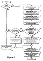
- the initial step is decision step 130 that queries whether a general alternate hypothesis exists. If so, control passes to decision step 132 that queries whether a target validates this hypothesis. If so, process step 134 updates the decision range with the road speed and acceleration of the target, and control passes to decision step 138. If the result from decision step 132 is that a target does not validate the hypothesis, then control passes to process step 136 that updates the decision range with the road speed and acceleration of host vehicle 10, and control passes to decision step 138. If the result from decision step 130 is that no general alternate hypothesis exists, control passes to decision step 138.
- Decision step 138 queries whether a primary alternate hypothesis exists. The closest in-lane target to the host is defined as the primary target. If a primary alternate hypothesis exists, control passes to decision step 140 which queries whether a target validates this hypothesis. If so, process step 142 updates the decision range with the road speed and acceleration of the target, and control passes to process step 114 of FIG. 7. If the result from decision step 140 is that a target does not validate the hypothesis, then control passes to process step 144 that updates the decision range with the road speed and acceleration of host vehicle 10, and control passes to process step 114 of FIG. 7. If the result from decision step 138 is that no primary alternate hypothesis exists, control passes to process step 114 of FIG. 7.
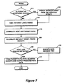
- a first indication of a lane change is a non-zero heading angle.
- a non-zero heading is indicative of a deviation from the predicted path or, equivalently, the predicted curvature rate.
- the routine must rotate and correlate the targets by the heading angle change. When host vehicle 10 performs a lane change, all targets will rotate by the heading change. If the targets are rotated back, the rotated positions should correlate to their previous positions. This is implemented by comparing the target path first order polynomial coefficient, c 1 , to the integrated yaw rate, i.e., the host vehicle heading irrespective of road geometry.
- the initial step is a process step 150, in which the unfiltered yaw rate measurement of host vehicle 10 is compared to the previous update path heading coefficient multiplied by twice the velocity of host vehicle 10.
- Decision step 152 queries whether this value exceeds a predetermined threshold. If the answer is negative, control passes to process step 154, which notes that host vehicle 10 is not changing lanes.
- decision step 158 if the majority of targets are not moving in a direction opposite to that of host vehicle 10, then host vehicle 10 is not changing lanes and control passes to step 154. If the answer at decision step 158 is positive, control passes to decision step 160, which queries whether there have been two consecutive detections on successive radar updates of such opposite motion. In this example, two consecutive detections of a majority of targets moving in a direction opposite to that of host vehicle 10 are required to validate a lane change by host vehicle 10.
- step 160 If the answer at decision step 160 is negative, the validation condition has not yet been met and control passes to process step 154. If the answer at decision step 160 is positive, the validation condition has been met and control passes to process step 162, which notes that host vehicle 10 is executing a lane change. Following either step 154 or step 162, control passes to process step 116 of FIG. 7.
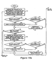
- FIGS. 10a through 10c which comprise, in fact, a single flow diagram broken out onto three sheets for readability and which is referred to collectively as FIG. 10, there is shown a detailed flow diagram of the process of step 116 of FIG. 7.
- This routine correlates target paths to the host vehicle path by examining the variance of the difference between path-fit cross range for the targets and yaw rate of host vehicle 10. Starting with the target furthest in range, referred to as the "pack leader,” if this target deviates from the host vehicle path, the system looks for a co-located target, defined, in the present example, by a moving target within 2.5 meters (based on a typical highway speed of 25 meters per second and a radar update rate of 10 per second).
- the program assumes a road deviation. This causes the weight in the path fusion to be increased so as to follow the deviation. If there is no neighboring target, then it is assumed that there is a road curvature change, and an alternate path hypothesis is set up. The active path will follow the target. The alternate path will ignore the target. The next closest target in range verifies or nullifies the path change. If, at a time calculated with target velocity and target range differential difference, the next target does not follow the lead target, but instead follows the alternate path, the program selects the alternate path and assumes the lead target is performing a lane change or exiting the highway.
- the initial step is process step 170, which computes the variance of the vector formed by subtracting the host vehicle predicted path cross range curve fit from the target path cross range curve fit minus the 0 th order polynomial coefficient, c 0 .
- Decision step 172 queries whether the variance from step 170 is greater than a threshold based on target range. If so, decision step 174 queries whether there have been two consecutive path change detections in successive radar updates. If so, process step 178 marks the target as having a path change, and control passes to decision step 180. If not, process step 176 marks the target as not having a path change, and control passes to decision step 180. If the result from decision step 172 is that the variance from step 170 is not greater than a threshold based on target range, process step 176 marks the target path as not having a path change, and control passes to decision step 180.
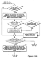
- Decision step 180 queries whether there is another vehicle trailing the target. If not, control passes to decision step 192. If there is a trailing vehicle, process step 182 computes the variance of the vector formed by subtracting the target and trailing target path cross range curve fits minus their 0 th order polynomial coefficients, c 0 . Decision step 184 then queries whether the variance from step 182 is greater than a range-based threshold. If so, decision step 186 queries whether there have been two such detections on consecutive radar updates. If so, process step 190 marks the target as having a lead-lag path change, and control passes to decision step 192. If not, process step 188 marks the target as not having a lead-lag path change, and control passes to decision step 192. If the result from decision step 184 is that the variance from step 182 is not greater than a range-based threshold, process step 188 marks the target as not having a lead-lag path change, and control passes to decision step 192.
- Decision step 192 queries whether there is another vehicle co-located to the target. If not, control passes to decision step 204. If there is a co-located vehicle, process step 194 computes the variance of the vector formed by subtracting the target and local target path cross range curve fits minus their 0 th order polynomial coefficient, c 0 . Decision step 196 then queries whether the variance from step 194 is greater than a range-based threshold. If so, decision step 198 queries whether there have been two such detections on consecutive radar updates. If so, process step 202 marks the target as having a local path change, and control passes to decision step 204. If not, process step 200 marks the target as not having a local path change, and control passes to decision step 204. If the result from decision step 196 is that the variance from step 194 is not greater than a range-based threshold, process step 200 marks the target as not having a local path change, and control passes to decision step 204.
- Decision step 204 queries whether the target validates an alternate hypothesis. If not, control passes to decision step 224. If the target does validate an alternate hypothesis, process step 206 computes the variance of the vector formed by subtracting the target and alternate hypothesis target path cross range curve fits minus their 0 th order polynomial coefficient, c 0 .
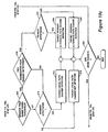
- Decision step 208 then queries whether the variance from step 206 is greater than a range-based threshold. If so, decision step 210 queries whether there have been two such detections on consecutive radar updates. If so, decision step 218 queries whether the validated hypothesis is a primary hypothesis. If so, process step 220 marks that a target primary alternate path change has been detected. Control then passes to decision step 224.
- decision step 218 finds that the validated hypothesis is not a primary hypothesis, process step 222 marks that a target general alternate path change has been detected. Control then passes to decision step 224. If decision step 210 fmds that there have not been two consecutive path change detections, control passes to decision step 212.
- decision step 212 queries whether the validated hypothesis is a primary hypothesis. If so, process step 214 marks that a target primary alternate path change has not been detected. Control then passes to decision step 224. If decision step 212 finds that the validated hypothesis is not a primary hypothesis, process step 216 marks that a target general alternate path change has not been detected. Control then passes to decision step 224.
- Step 224 queries whether there are any more targets to test. If so, control passes back to step 170 at the top of the routine. If there are no more targets, control returns to step 118 of FIG. 7.
- step 118 of FIG. 7 fusion weights are generated, by default, based on the range of the target from host vehicle 10. The weights will be adjusted in subsequent operations described in relation to FIGS. 12a through 12c.
- the default weights are assigned a value of one for the range between host vehicle 10 and the present position of the target, and monotonically decreasing values beyond the target to the end of the range of radar system 14. Thus, it may be seen that the closest target exerts the greatest influence when the weights are fused.
- the initial step is decision step 230, which queries whether a primary alternate hypothesis has been accepted. If so, process step 232 clears the general alternate hypothesis and control passes to process step 234. If no primary alternate hypothesis has been accepted, control passes directly to step 234.
- step 234 the above-mentioned default range-based weight is applied.
- decision step 236 queries whether an alternate path hypothesis has been accepted or rejected. If not, control passes back to decision step 120 of FIG. 7. If an alternate path hypothesis has been accepted or rejected, step 238 adjusts the fusion weights. If a target has been rejected due to a hypothesis, its weight is set to zero. Following step 238, control passes back to decision step 120 of FIG. 7.
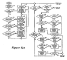
- FIGS. 12a through 12c which comprises, in fact, a single flow diagram broken out onto three sheets for readability and which is referred to collectively as FIG. 12, there is shown a detailed flow diagram of the process of step 122 of FIG. 7.
- This routine is a decision tree for path prediction.
- Outputs of the correlation analyses are run through a series of decisions that control the fusion weights. Alternate hypotheses are set, maintained, and resolved as well.
- process step 240 which identifies the target furthest in range, also called the pack leader.
- Decision step 242 queries whether the path of the pack leader is changing. If not, control passes to process step 250. If so, decision step 244 queries whether a co-located target exists. If not, process step 252 sets an alternate hypothesis to not follow the pack leader, and control passes to process step 250.
- decision step 244 determines that a co-located target exists, control passes to decision step 246.
- Decision step 246 queries whether the path of the co-located target is changing. If not, process step 254 follows the co-located target and sets an alternate hypothesis to follow the pack leader, and control passes to continuation step 258. If decision step 246 determines that the path of the co-located target is changing, control passes to decision step 248, which queries whether the change in the co-located target path is correlated to the path change of the pack leader. If so, control passes to process step 250. If decision step 248 determines that the two paths are not correlated, process step 256 sets an alternate hypothesis to follow the co-located target, and control passes to process step 250.
- Process step 250 instructs the routine to continue following the pack leader, and the following step, continuation step 258, passes control to decision step 260.
- Decision step 260 queries whether there are any more targets in range. If not, decision step 262 queries whether host vehicle 10 validates the alternate hypothesis. If not, control passes to continuation step 290. If host vehicle 10 does validate the alternate hypothesis, decision step 280 queries whether the decision range has been reached. If so, decision step 284 queries whether host vehicle 10 is correlated to the alternate target path. If not, process step 288 decrements the decision count and control passes to continuation step 290. If decision step 284 determines that host vehicle 10 is correlated to the alternate target path, process step 286 increments the decision count and control passes to continuation step 290.
- decision step 282 queries whether host vehicle 10 is correlated to the alternate target path. If not, control passes to continuation step 290. If decision step 282 determines that host vehicle 10 is correlated to the alternate target path, process step 286 increments the decision count and control passes to continuation step 290.
- decision step 264 queries whether the next target validates the alternate hypothesis. If so, decision step 266 queries whether the decision range has been reached. If so, decision step 270 queries whether the target's path is changing. If not, process step 274 decrements the decision count and control passes to continuation step 278. If decision step 270 determines that the target's path is changing, decision step 272 queries whether the target is correlated to the alternate target path. If so, process step 276 increments the decision count and control passes to continuation step 278. If decision step 272 determines that the target is not correlated to the alternate target path, control passes to continuation step 278.
- decision step 268 queries whether the target's path is changing. If not, control passes to continuation step 278. If decision step 282 determines that the target's path is changing, process step 276 increments the decision count and control passes to continuation step 278.
- decision step 292 queries whether the target's path is changing. If not, control passes to continuation step 296. If decision step 292 determines that the target's path is changing, decision step 294 queries whether the target path change is correlated to the path of the leading target. If so, control passes to continuation step 296. If decision step 294 determines that the target's path is not correlated to the path of the leading target, decision step 298 queries whether a co-located target exists. If not, decision step 302 queries whether the target is the primary target, i.e., the target closest to host vehicle 10. If so, process step 310 sets the primary alternate hypothesis to follow the primary target, and control passes to continuation step 296.
- decision step 302 determines that the target is not the primary target
- decision step 304 queries whether an alternate hypothesis exists for a further range target. If not, process step 306 sets an alternate hypothesis to follow the target, and control passes to continuation step 296. If decision step 304 determines that an alternate hypothesis exists for a further range target, process step 308 continues with the existing alternate hypothesis, and control passes to continuation step 296.
- decision step 300 queries whether the path of the co-located target is changing. If the path of the co-located target is not changing, control passes to decision step 302. If decision step 300 determines that the path of the co-located target is changing, decision step 312 queries whether the path change of the co-located target is correlated to the path change of the target. If the path change of the co-located target is not correlated to the path change of the target, decision step 314 queries whether either the target or the co-located target is the primary target.
- process step 316 reduces the fusion weight on the non-primary target, and control passes to process step 310. If decision step 314 determines that neither the target nor the co-located target is the primary target, process step 322 reduces the fusion weights on both targets, and control passes to continuation step 296.
- decision step 318 queries whether either the target or the co-located target is the primary target. If a decision is made that either the target or the co-locked target is the primary target, process step 320 sets the primary alternate hypothesis to follow the target and the co-located target, and control passes to continuation step 296. If decision step 318 determines that neither the target nor the co-located target is the primary target, decision step 324 queries whether an alternate hypothesis exists for a further range target. If no alternate hypothesis exists, process step 326 sets an alternate hypothesis to follow the target and the co-located target, and control passes to continuation step 296. If decision step 324 determines that an alternate hypothesis exists for a further range target, control passes to process step 308, which continues with the existing alternate hypothesis, and control then passes to continuation step 296.
- Continuation step 296 passes control back to decision step 260.
- Continuation steps 278 and 290 pass control to decision step 328.
- Decision step 328 queries whether the decrement count limit has been exceeded. If it has, then the alternate hypothesis is rejected in process step 330 and control passes to continuation step 338. If decision step 328 determines that the decrement count limit has not been exceeded, then decision step 332 queries whether the increment count limit has been reached. If it has, then the alternate hypothesis is accepted in process step 334 and control passes to continuation step 338. If decision step 332 determines that the increment count limit has been not reached, then decision step 336 queries whether the maximum time past decision range has been exceeded. If it has, control passes to process step 334; if not, control passes to continuation step 338. Continuation step 338 passes control back to decision step 124 of FIG. 7.
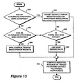
- step 124 of FIG. 7 there is shown a detailed flow diagram of the process of step 124 of FIG. 7, in which the target paths are fused with adjusted weights and predicted path data is generated.
- the fusion is a weighted average of the target paths projected from the polynomial curve fits data.
- the cross range component is removed from target paths prior to fusion. If there is only one target and it has been rejected upon with hypothesis testing, host path data is used.
- the initial step is a decision step 340, which queries whether an alternate hypothesis has been accepted. If an alternate hypothesis has been accepted, control passes to process step 346, which adjusts the fusion weights based on the resolution of the hypothesis. Control then passes to process step 352. Step 352 computes the weighted average of the target paths and extracts the coefficients of the polynomial. Control then passes back to process step 40 of FIG. 3.
- decision step 340 determines that no alternate hypothesis has been accepted, then processing proceeds to decision step 342 which queries whether an alternate hypothesis has been rejected. If an alternate hypothesis has been rejected, decision step 348 queries whether there is only a single target. If there is only a single target, step 350 instructs the process to use the host vehicle derived path, and control again passes to process step 352.
- step 348 determines that there is more than one target, control passes to process step 346 and then to step 352.
- step 344 applies default, range-based fusion weights, and control again passes to process step 352.
- step 40 of FIG. 3 there is shown a detailed flow diagram of the process of step 40 of FIG. 3.
- the target cross range positions are compared to the predicted path of host vehicle 10 and the targets are classified as either in-lane or out-of-lane of the host vehicle highway lane.
- target positions are compared to within one-half a highway lane width of the predicted path to determine in-lane classification. The closest in-lane target to the host is selected as the primary target. If there are no in-lane targets, then there is no primary target.
- the cross range bounds of the predicted path of host vehicle 10 at the longitudinal range of that target are computed.
- Decision step 362 queries whether the target cross range is within the bounds of the highway lane width. If the target cross range is not within the bounds of the highway lane width, process step 364 identifies the target as not being in the lane of host vehicle 10. If the target cross range is within the bounds of the highway lane width, process step 366 identifies the target as being in the lane of host vehicle 10.
- Steps 364 and 366 both pass control to decision step 368 which queries if any more targets are to be checked. If there are more targets to be so identified, control passes back to step 360. If there are no more targets, process step 370 selects the in-lane target at the closest longitudinal distance from host vehicle 10 as being the primary target.
- control returns to the routine of FIG. 3 where, following the next radar update, process step 30 is re-entered.
Landscapes
- Engineering & Computer Science (AREA)
- Remote Sensing (AREA)
- Radar, Positioning & Navigation (AREA)
- Physics & Mathematics (AREA)
- General Physics & Mathematics (AREA)
- Computer Networks & Wireless Communication (AREA)
- Electromagnetism (AREA)
- Automation & Control Theory (AREA)
- Aviation & Aerospace Engineering (AREA)
- Human Computer Interaction (AREA)
- Transportation (AREA)
- Mechanical Engineering (AREA)
- Radar Systems Or Details Thereof (AREA)
- Traffic Control Systems (AREA)
Abstract
Description
- The present invention relates generally to automotive driver aids and, more particularly, to a path prediction system and method for use with adaptive cruise control and collision avoidance systems for an automotive vehicle, the path prediction system tracking targets in the same highway lane as the vehicle.
- In view of the improvements in the technology of automotive features, there is an ongoing opportunity to provide features that enhance driver convenience. One possible area of increased automobile convenience involves the vehicle's cruise control system. A cruise control system permits an operator to set a predetermined speed of travel and controls the vehicle to maintain the predetermined speed. Hereinafter, the driver's vehicle may be referred to as the "host vehicle."
- When employing the cruise control system, as the host vehicle approaches an obstacle in the highway, such as another vehicle in the driver's lane, driver attention and intervention are necessary to override the cruise control system by actuating the host vehicle's brakes and thereby avoid a collision.
- To enhance the convenience of cruise control systems, "intelligent" cruise control systems have been suggested. Intelligent cruise control systems typically include a detector for detecting obstacles in the path of the vehicle and a controller for actuating the vehicle's brakes and overriding the cruise control system in response to the detection of obstacles. Advantageously, intelligent cruise control systems can reduce the dependence on the driver for avoiding collisions.
- Another possible area of increased automotive convenience is in collision avoidance systems. Like intelligent cruise control systems, collision avoidance systems generally include a detector for detecting obstacles in the path of the host vehicle and a controller for actuating the vehicle's brakes in response to detected obstacles in order to avoid collisions.
- US 5 689 264 teaches an obstacle detection system for vehicles.
- In both the intelligent cruise control and collision avoidance applications, it is necessary to provide a detector capable of accurately and reliability detecting objects in the path of the vehicle. Such a detector must be relatively insensitive to the relative location of the automobile and obstacles. One problem with cruise control systems and collision avoidance systems, however, is that they can stop detecting obstacles in front of the host vehicle as the obstacle or host vehicle turns a corner. These systems are also susceptible to reduced effectiveness under certain environmental conditions, such as precipitation, fog or haze, high humidity, and extremes of temperature.
- It would, therefore, be desirable to provide a system that is capable of detecting the presence of an obstacle in the forward path of a vehicle when either or both of the vehicle and the obstacle are traveling on either a straight or curved path.
- In view of the above-stated needs and in accordance with the present invention, it has been recognized that combining the need for increased automotive convenience with the usefulness and desirability of obstacle detection leads to the problem of providing a path prediction system and method which is simple, accurate, cost-effective and reliable, given the environmental and other operating conditions under which such a system and method must operate. It would, therefore, be desirable to fill the need for a system and method that provides a reliable indication of the presence of obstacles forward of and in the same highway lane as an automotive vehicle.
- In accordance with the principles of the present invention, there is disclosed herein a system for detecting objects in a predicted path of a host vehicle moving on a highway lane. The detecting system includes a forward looking sensor for providing range, angle and velocity data for objects within a field of view in front of the vehicle. The detecting system also includes measuring systems for providing velocity and yaw rate data for the host vehicle. The detecting system further includes a processing system responsive to the forward looking sensor and the measuring systems for calculating an estimated path of the vehicle based on its velocity and yaw rate, calculating estimated paths for each of the objects, determining the lateral distance of each object from the predicted path of the vehicle, classifying each object as either in or out of the highway lane of the vehicle and generating the predicted path of the vehicle by correlating the estimated path of the vehicle and the estimated paths of the objects and fusing the paths of the objects as a weighted average.
- In a preferred embodiment of the present invention, the forward looking sensor comprises a radar system and the yaw rate measuring system comprises a gyrocompass or other angular rate sensor.
- Further in accordance with the principles of the present invention, there is disclosed herein a method for detecting objects in a predicted path of a vehicle moving on a highway lane. The method is for use in a system including a forward looking sensor for providing range, angle and velocity data for objects within a field of view in front of the vehicle, measuring systems for providing velocity and yaw rate data for the vehicle, and a processing system responsive to the forward looking sensor and the measuring systems. The method comprises the steps of (a) calculating an estimated path of the vehicle based on its velocity and yaw rate; (b) calculating estimated paths for each of the objects; (c) determining the lateral distance of each object from the predicted path of the vehicle; and (d) classifying each object as either in or out of the highway lane of the vehicle and generating the predicted path of the vehicle by correlating the estimated path of the vehicle and the estimated paths of the objects and fusing the paths of the objects as a weighted average.
- Preferably the method comprises the steps of (i) collecting data inputs from the forward looking radar system and the measuring systems, and deriving acceleration and lateral velocity target data therefrom; (ii) propagating target position histories with the host vehicle path estimate; and propagating target positions forward with longitudinal and lateral target position stage vectors; (iii) calculating polynomial curve fits for host vehicle and target position vectors; (iv) comparing target cross range positions to the predicted path and classifying targets as in-lane or out-of-lane with respect to the highway lane of the host vehicle; (v) receiving updated data from the forward looking radar system; and (vi) repeating steps (i) through (iv) continuously.
- The method cited immediately above includes a process of testing for a highway lane change by the host vehicle. This process includes confirming such a highway lane change by comparing the integrated yaw rate to each target heading coefficient to see if it is equal and opposite, confirming that the majority of targets are moving in the opposite direction of the host vehicle, and noting that the opposite direction motion has occurred at two consecutive data updates from the forward looking radar system.
- The foregoing features of the present invention may be more fully understood from the following detailed description, read in conjunction with the accompanying drawings, wherein:
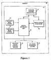
- FIG. 1 illustrates a vehicle having a path prediction system in accordance with the present invention;
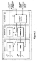
- FIG. 2 illustrates a prior art radar system, which may be used as the forward looking sensor of FIG. 1;
- FIG. 3 is an overview flow diagram illustrating a technique employed by the signal processing system of FIG. 1 to implement target detection in the predicted path of the vehicle of FIG. 1;
- FIGS. 4 through 7 and 14 are flow diagrams providing more detailed descriptions of the processing steps of the overview flow diagram of FIG. 3; and
- FIGS. 8, 9, 10a through 10c, 11, 12a through 12c, and 13 are flow diagrams providing more detailed descriptions of the processing steps of the flow diagram of FIG. 7.
- Like reference numbers and designations in the various figures refer to identical or substantially identical elements.
- Throughout this description, the preferred embodiment and examples shown should be considered as exemplars, rather than as limitations on the present invention.
- Referring initially to FIG. 1, there is shown a
vehicle 10 including asystem 12 for detecting objects in a predicted path of the vehicle as it moves along a highway lane. Hereinafter,vehicle 10 may be referred to as the "host vehicle."Detection system 12 includes a forward lookingsensor 14 that provides range, velocity and angle data for objects within the field of view of forward lookingsensor 14 in front ofvehicle 10. -
Detection system 12 also includes avelocity measuring system 16 for measuring the speed ofvehicle 10.Detection system 12 further includes a yawrate measuring system 18 for measuring the yaw rate ofvehicle 10. Still further,detection system 12 includesdigital interface unit 22 for communicating different forms of data signals among the several subsystems illustrated in FIG. 1. Finally,detection system 12 includes asignal processing system 20, responsive to the data outputs of forward lookingsensor 14,velocity measuring system 16 and yawrate measuring system 18, for generating signals to adaptivecruise control system 24 andcollision avoidance system 26, the signals indicative of targets that have been detected in a predicted path ofvehicle 10 as it moves along a highway lane. - Radar is a suitable technology for implementing an automotive forward looking sensor. One type of radar particularly suitable for this purpose is frequency modulated continuous wave (FMCW) radar. In typical FMCW radar, the frequency of the transmitted CW signal linearly increases from a first predetermined frequency to a second predetermined frequency, and then repeats the frequency sweep in the opposite direction. FMCW radar has the advantages of high sensitivity, relatively low transmitter power and good range resolution.
- Referring now to FIG. 2, in a preferred embodiment of the present invention, which may be of the type described in U.S. Patent No. 5,929,802, entitled, "Automotive Forward Looking Sensor Architecture," issued July 27, 1999, and which is incorporated herein by reference in its entirety, forward looking
sensor 14 includes anantenna assembly 414, amicrowave assembly 420 having both atransmitter 422 and areceiver 424, and anelectronic assembly 428, includingcontrol circuits 434. Forward lookingsensor 14 utilizes radar technology and is adapted for mounting on a vehicle to detect one or more objects, or targets in the field of view of forward lookingsensor 14. In this application, the targets include other cars, trees, signs, pedestrians, etc. - In response to control signals from
velocity measuring system 16 and yawrate measuring system 18, and reflected RF signals received by forward lookingsensor 14,sensor 14 provides one or more output signals characterizing each target within its field of view. These output signals relate to the range of each target in the field of view ofsensor 14, the range rate, or velocity, associated with each target, and azimuth, or angle, associated with each target relative tovehicle 10. - The
antenna assembly 414 includes two antennas, a receiveantenna 416 for receiving RF signals and atransmit antenna 418 for transmitting RF signals. Forward lookingsensor 14 may be characterized as a bi-static radar sensor since it includes separate transmit and receive antennas.Antennas respective antennas - The output from the
receive antenna 416 is coupled to themicrowave receiver 424, where one or more local oscillator signals are offset in frequency from the transmitted signal frequency by a fixed amount. The output signal of thereceiver 424 is at an offset frequency, with the target frequencies either above or below it. - The
receiver 424 includes an analog-to-digital (A/D) converter that samples an amplified version of the received RF signal at a rate at least twice the largest frequency out of the receiver. These signal samples are processed by an FFT in order to determine the content of the signal within various frequency ranges. The FFT outputs serve as data todigital signal processor 20. The manner by whichdigital signal processor 20 processes received RF signals to provide the above-described output signals to thevehicle 10 indicative of range, range rate and azimuth of a target is described in U.S. Patent No. 6,011,507, entitled "Radar System and Method of Operating Same," issued on January 4, 2000, which is incorporated herein by reference in its entirety. - In one embodiment, forward looking
sensor 14 includes an antenna assembly having seven antenna beams. The use of multiple antenna beams allows multiple objects at distances in the range of about 120 meters to as much as 150 meters from forward lookingsensor 14 to be accurately resolved. - Referring back again to FIG. 1,
velocity measuring system 16 typically consists of a speedometer that provides a signal todigital interface unit 22 indicative of the speed ofhost vehicle 10. Yawrate measuring system 18 preferably comprises a gyrocompass or similar angular rate sensor that provides a signal todigital interface unit 22 indicative of the yaw rate ofhost vehicle 10.Digital interface unit 22 couples data and control signals among forward lookingsensor 14,velocity measuring system 16, yawrate measuring system 18,digital signal processor 20, adaptivecruise control system 24 andcollision avoidance system 26. -
Signal processing system 20 is preferably a programmable digital signal processor that responds to the signals received from forward lookingsensor 14 anddigital interface unit 22 to perform the processes which are described in detail in the following paragraphs. The results of these processes are data that are coupled throughdigital interface unit 22 for application to, for example, adaptivecruise control system 24 andcollision avoidance system 26, these data relating to the detection of one or more objects in the predicted path ofhost vehicle 10. - Referring now to FIG. 3, there is shown an overview flow diagram illustrating a technique employed by
signal processing system 20 of FIG. 1 to implement target detection in the predicted path ofhost vehicle 10. This flow diagram comprises of an endless loop which cycles once for each update of the radar system employed as forward lookingsensor 14. In the intended use of the present invention, it is estimated that such updates will occur once every 50-100 milliseconds, or 10-20 cycles through the loop of FIG. 3 per second. - At
process step 30,signal processing system 20 collects the data inputs. From forward lookingsensor 14 it receives data, for each tracked target, relating to the range, angle, velocity and acceleration relative to hostvehicle 10. From this information,system 20 converts the data to range, angle, velocity and acceleration. It uses the angle and the range to calculate lateral velocity. At this process step,system 20 also inputs the velocity and yaw rate ofvehicle 10 fromvelocity measuring system 16 and yawrate measuring system 18, respectively. - The process of FIG. 3 continues with
process step 32 in which a path forhost vehicle 10 is estimated based on its velocity and yaw rate. The host vehicle path estimate is calculated by application of a 2-state Kalman filter to track curvature parameters and propagate a host position vector forward in range. The details of this process will be more completely described in a later discussion in relation to FIG. 4. - The process of FIG. 3 continues with
process step 34 in which, for each target, position histories are propagated based on host vehicle speed and yaw rate, and target positions are propagated forward with longitudinal and lateral position state vectors. The details of this process will be more completely described in a later discussion in relation to FIG. 5. - The process of FIG. 3 continues with
process step 36 in which a curve fit is applied to the host vehicle curvature rate data and, for each target, a curve is generated using target history data and data propagated forward from position and velocity estimates in the longitudinal and lateral directions. The details of this process will be more completely described in a later discussion in relation to FIG. 6. - The process of FIG. 3 continues with
process step 38 in which a predicted path is generated by correlating host and target paths and fusing weighted target paths. The details of this process will be more completely described in a later discussion in relation to FIG. 7. - The process of FIG. 3 continues with a
final process step 40 in which target cross range positions are compared to the predicted path ofhost vehicle 10 and the targets are classified as either in or out of the host lane. The details of this process will be more completely described in a later discussion in relation to FIG. 14. - After completion of
process step 40, there is an update of the radar system employed as forward lookingsensor 14, and signal processing system entersprocess step 30 with the updated target data. - Referring now to FIG. 4, there is shown a detailed flow diagram of the process of
step 32 of FIG. 3. In this step, a path forhost vehicle 10 is estimated based on its velocity and yaw rate. The host vehicle path estimate is calculated by application of a 2-state Kalman filter to track curvature parameters and propagate a host position vector forward in range. The curvature state vector consists of curvature rate (degrees/meter) and curvature rate change (degrees/meter2). The Kalman filter averages the curvature rate from update to update by weighting according the variances of measurement. It filters out extremes of the noise, e.g., spikes of yaw rate caused by bumps in the highway. A curvature rate measurement is generated by dividing the yaw rate by the vehicle speed. After filtering the curvature state vector, it is propagated forward with the state transition matrix and the path is propagated forward from the center of the host vehicle in fixed-length steps along an arc. In the present example, the steps are 10 meters in length. - The process of
step 32 begins atdecision step 50 which queries whether the current update is the first update. If it is, control passes to step 52 in which the Kalman filter is initialized, and control passes to step 70. If it is not the first update, control passes to step 54 where the distance the host vehicle has traveled is estimated. The elapsed time since the last estimate is computed, and this elapsed time is used with the host vehicle's speed to compute the distance traveled. In the step that follows, step 56, the distance traveled is used to define a state transition matrix and a state covariance drift matrix. Atstep 58, the state transition and covariance drift matrices are used to predict the state vector and state vector covariance. The state vector is then used to predict the measurement. Atstep 60, the curvature rate measurement and measurement variance are computed using the yaw rate, velocity and variances. - At
decision step 62, a measurement prediction window must be determined. The window defines a two-sided bound for which measurements will be accepted. In this example, the measurement is the same quantity as the first element in the state vector, and the threshold bound is three times the square root of that state element variance plus the measurement noise estimate. A determination is made as to whether to perform a measurement update by comparing the difference of the measurement and the predicted measurement with the threshold. - If the update is to be executed, control passes to process
step 68 where the Kalman gain is computed and the state vector and covariance are updated. If the update is not to be executed, control passes todecision step 64 where the elapsed time is tested since the last valid update. If some maximum time has been exceeded, then the Kalman filter is reinitialized atprocess step 52 and control passes to processstep 70. If the maximum time has not been exceeded, control passes to processstep 66 where the state vector and covariance are taken to be the prediction values. Control then passes to processstep 70 where the current curvature rate and curvature rate change are propagated out along a curved path at fixed step sizes. - At
process step 72, the x- and y-coordinates for each propagated position are determined using a Cartesian coordinate system where x is positive to the right ofhost vehicle 10 and y is straight ahead ofhost vehicle 10. At the conclusion ofprocess step 72, control passes to processstep 34 of FIG. 3. - Referring now to FIG. 5, there is shown a detailed flow diagram of the process of
step 34 of FIG. 3 in which, for each target, position histories are propagated based on host vehicle speed and yaw rate, and target positions are propagated forward with longitudinal and lateral position state vectors. - At the
initial process step 80, the longitudinal and lateral heading vector ofhost vehicle 10 is calculated from the yaw rate, velocity and time elapsed since the last update. Atprocess step 82, for the first target, the target position history points are propagated and rotated in accordance with the updated heading vector ofhost vehicle 10. Atstep 84, any points of the target position history that have fallen behind host vehicle, i.e., the x coordinate is negative, are deleted from the history. - At
decision step 86, the process queries whether the target is on a straight road, not executing a lane change and within an allowable range. If any of these conditions is false, control passes todecision step 90. If all of these conditions are true, control passes to processstep 88 where the target positions are propagated forward with longitudinal and lateral target position state vectors and a state transition matrix. Control then passes todecision step 90 which queries whether all targets have undergone the propagation updates of steps 82-88. If not, control returns to step 82 for the next target. If all targets have been so propagated,decision step 90 passes control to processstep 36 of FIG. 3. - Referring now to FIG. 6, there is shown a detailed flow diagram of the process of
step 36 of FIG. 3. In this process a curve fit is applied to the host vehicle curvature rate data and, for each target, a curve is generated using target history data and data propagated forward from position and velocity estimates in the longitudinal and lateral directions. The curves are both second-order polynomials of the form
where x is the lateral direction and y is the longitudinal direction, and where c0, c1 and c2 are the 0th, 1st, and 2nd order polynomial coefficients, respectively, that specify the shape of the curve in the cross range dimension. - The initial step is
process step 100 that generates a fixed longitudinal vector. This is followed byprocess step 102 that applies a second-order polynomial curve fit to the host vehicle predicted position vector. Cross range polynomial coefficients (c0, c1 and c2) are generated, and evaluated against the fixed longitudinal vector. -
Decision step 104 queries whether a sufficient number of target position points have been read. In the present example, at the aforementioned radar scan rate of 10-20 radar updates per second, a two-second period provides 10 to 20 target position points. This is deemed sufficient for a satisfactory curve fit. If a sufficient number of target position points have not been read, control passes todecision step 108. If a sufficient number have been read, control passes to processstep 106 where a second-order polynomial curve fit is applied to the target position history/prediction vector. Cross range polynomial coefficients (c0, c1 and c2) are generated, and evaluated against the fixed longitudinal vector. - Control then passes to
decision step 108 which queries whether all targets have been examined. If not, control passes back todecision step 104 for the next target. If all targets have been examined,decision step 108 passes control to processstep 38 of FIG. 3. - Referring now to FIG. 7, there is shown a detailed flow diagram of the process of
step 38 of FIG. 3.Process step 38 generates a predicted path by correlating host and target paths and fusing weighted target paths. - The initial step is
decision step 110 that queries whether alternate path hypotheses exist. A discussion of alternate path hypotheses is provided in the text relating to FIG. 10. If an alternate path hypothesis exists,process step 112 updates the decision range from the previous update. The details ofprocess step 112 will be more completely described in a later discussion in relation to FIG. 8. Followingstep 112, control passes to processstep 114. If alternate hypotheses do not exist,process step 114 tests to determine ifhost vehicle 10 is executing a lane change. The details ofprocess step 114 will be more completely described in a later discussion in relation to FIG. 9. - Control now passes to process
step 116, which correlates the host and target paths. The details ofprocess step 116 will be more completely described in a later discussion in relation to FIGS. 10a through 10c. Followingstep 116,process step 118 generates fusion weights, by default, based on the range of the target fromhost vehicle 10. The details ofprocess step 118 will be more completely described in a later discussion in relation to FIG. 11. - Following
step 118,decision step 120 queries whether a lane change ofhost vehicle 10 has been detected. If not,process step 122 executes a path decision tree, which will be more completely described in a later discussion in relation to FIGS 12a through 12c. Control then passes to step 124 where the target paths are fused and the predicted path data is generated. Ifdecision step 120 determines that a lane change has been detected, control passes to processstep 124 where the target paths are fused and the predicted path data is generated. The details ofprocess step 124 will be more completely described in a later discussion in relation to FIG. 13. At the conclusion ofprocess step 124, control passes to processstep 40 of FIG. 3. - Referring now to FIG. 8, there is shown a detailed flow diagram of the process of
step 112 of FIG. 7. The initial step isdecision step 130 that queries whether a general alternate hypothesis exists. If so, control passes todecision step 132 that queries whether a target validates this hypothesis. If so,process step 134 updates the decision range with the road speed and acceleration of the target, and control passes todecision step 138. If the result fromdecision step 132 is that a target does not validate the hypothesis, then control passes to processstep 136 that updates the decision range with the road speed and acceleration ofhost vehicle 10, and control passes todecision step 138. If the result fromdecision step 130 is that no general alternate hypothesis exists, control passes todecision step 138. -
Decision step 138 queries whether a primary alternate hypothesis exists. The closest in-lane target to the host is defined as the primary target. If a primary alternate hypothesis exists, control passes todecision step 140 which queries whether a target validates this hypothesis. If so,process step 142 updates the decision range with the road speed and acceleration of the target, and control passes to process step 114 of FIG. 7. If the result fromdecision step 140 is that a target does not validate the hypothesis, then control passes to processstep 144 that updates the decision range with the road speed and acceleration ofhost vehicle 10, and control passes to process step 114 of FIG. 7. If the result fromdecision step 138 is that no primary alternate hypothesis exists, control passes to process step 114 of FIG. 7. - Referring now to FIG. 9, there is shown a detailed flow diagram of the process of
step 114 of FIG. 7. This is a routine that tests for lane changes byhost vehicle 10. A first indication of a lane change is a non-zero heading angle. A non-zero heading is indicative of a deviation from the predicted path or, equivalently, the predicted curvature rate. The routine must rotate and correlate the targets by the heading angle change. Whenhost vehicle 10 performs a lane change, all targets will rotate by the heading change. If the targets are rotated back, the rotated positions should correlate to their previous positions. This is implemented by comparing the target path first order polynomial coefficient, c1, to the integrated yaw rate, i.e., the host vehicle heading irrespective of road geometry. - The initial step is a
process step 150, in which the unfiltered yaw rate measurement ofhost vehicle 10 is compared to the previous update path heading coefficient multiplied by twice the velocity ofhost vehicle 10.Decision step 152 then queries whether this value exceeds a predetermined threshold. If the answer is negative, control passes to processstep 154, which notes thathost vehicle 10 is not changing lanes. - If the values compared in
step 150 exceed the threshold indecision step 152, control passes to processstep 156 which compares the integrated yaw rate ofhost vehicle 10 to each target heading coefficient to determine if it is equal and opposite. Atdecision step 158, if the majority of targets are not moving in a direction opposite to that ofhost vehicle 10, then hostvehicle 10 is not changing lanes and control passes to step 154. If the answer atdecision step 158 is positive, control passes todecision step 160, which queries whether there have been two consecutive detections on successive radar updates of such opposite motion. In this example, two consecutive detections of a majority of targets moving in a direction opposite to that ofhost vehicle 10 are required to validate a lane change byhost vehicle 10. If the answer atdecision step 160 is negative, the validation condition has not yet been met and control passes to processstep 154. If the answer atdecision step 160 is positive, the validation condition has been met and control passes to processstep 162, which notes thathost vehicle 10 is executing a lane change. Following either step 154 or step 162, control passes to process step 116 of FIG. 7. - Referring now to FIGS. 10a through 10c, which comprise, in fact, a single flow diagram broken out onto three sheets for readability and which is referred to collectively as FIG. 10, there is shown a detailed flow diagram of the process of
step 116 of FIG. 7. This routine correlates target paths to the host vehicle path by examining the variance of the difference between path-fit cross range for the targets and yaw rate ofhost vehicle 10. Starting with the target furthest in range, referred to as the "pack leader," if this target deviates from the host vehicle path, the system looks for a co-located target, defined, in the present example, by a moving target within 2.5 meters (based on a typical highway speed of 25 meters per second and a radar update rate of 10 per second). If the co-located target is also deviating from the host vehicle path, and the target paths are correlated, then the program assumes a road deviation. This causes the weight in the path fusion to be increased so as to follow the deviation. If there is no neighboring target, then it is assumed that there is a road curvature change, and an alternate path hypothesis is set up. The active path will follow the target. The alternate path will ignore the target. The next closest target in range verifies or nullifies the path change. If, at a time calculated with target velocity and target range differential difference, the next target does not follow the lead target, but instead follows the alternate path, the program selects the alternate path and assumes the lead target is performing a lane change or exiting the highway. - The initial step is
process step 170, which computes the variance of the vector formed by subtracting the host vehicle predicted path cross range curve fit from the target path cross range curve fit minus the 0th order polynomial coefficient, c0.Decision step 172 then queries whether the variance fromstep 170 is greater than a threshold based on target range. If so,decision step 174 queries whether there have been two consecutive path change detections in successive radar updates. If so,process step 178 marks the target as having a path change, and control passes todecision step 180. If not,process step 176 marks the target as not having a path change, and control passes todecision step 180. If the result fromdecision step 172 is that the variance fromstep 170 is not greater than a threshold based on target range,process step 176 marks the target path as not having a path change, and control passes todecision step 180. -
Decision step 180 queries whether there is another vehicle trailing the target. If not, control passes todecision step 192. If there is a trailing vehicle,process step 182 computes the variance of the vector formed by subtracting the target and trailing target path cross range curve fits minus their 0th order polynomial coefficients, c0.Decision step 184 then queries whether the variance fromstep 182 is greater than a range-based threshold. If so,decision step 186 queries whether there have been two such detections on consecutive radar updates. If so,process step 190 marks the target as having a lead-lag path change, and control passes todecision step 192. If not,process step 188 marks the target as not having a lead-lag path change, and control passes todecision step 192. If the result fromdecision step 184 is that the variance fromstep 182 is not greater than a range-based threshold,process step 188 marks the target as not having a lead-lag path change, and control passes todecision step 192. -
Decision step 192 queries whether there is another vehicle co-located to the target. If not, control passes todecision step 204. If there is a co-located vehicle,process step 194 computes the variance of the vector formed by subtracting the target and local target path cross range curve fits minus their 0th order polynomial coefficient, c0.Decision step 196 then queries whether the variance fromstep 194 is greater than a range-based threshold. If so,decision step 198 queries whether there have been two such detections on consecutive radar updates. If so,process step 202 marks the target as having a local path change, and control passes todecision step 204. If not,process step 200 marks the target as not having a local path change, and control passes todecision step 204. If the result fromdecision step 196 is that the variance fromstep 194 is not greater than a range-based threshold,process step 200 marks the target as not having a local path change, and control passes todecision step 204. -
Decision step 204 queries whether the target validates an alternate hypothesis. If not, control passes todecision step 224. If the target does validate an alternate hypothesis,process step 206 computes the variance of the vector formed by subtracting the target and alternate hypothesis target path cross range curve fits minus their 0th order polynomial coefficient, c0. -
Decision step 208 then queries whether the variance fromstep 206 is greater than a range-based threshold. If so,decision step 210 queries whether there have been two such detections on consecutive radar updates. If so,decision step 218 queries whether the validated hypothesis is a primary hypothesis. If so,process step 220 marks that a target primary alternate path change has been detected. Control then passes todecision step 224. - If
decision step 218 finds that the validated hypothesis is not a primary hypothesis,process step 222 marks that a target general alternate path change has been detected. Control then passes todecision step 224. Ifdecision step 210 fmds that there have not been two consecutive path change detections, control passes todecision step 212. - If
decision step 208 finds that the variance fromstep 206 is not greater than a range-based threshold, control passes todecision step 212.Decision step 212 queries whether the validated hypothesis is a primary hypothesis. If so,process step 214 marks that a target primary alternate path change has not been detected. Control then passes todecision step 224. Ifdecision step 212 finds that the validated hypothesis is not a primary hypothesis,process step 216 marks that a target general alternate path change has not been detected. Control then passes todecision step 224. -
Decision step 224 queries whether there are any more targets to test. If so, control passes back to step 170 at the top of the routine. If there are no more targets, control returns to step 118 of FIG. 7. - Referring now to FIG. 11, there is shown a detailed flow diagram of the process of
step 118 of FIG. 7. In this step, fusion weights are generated, by default, based on the range of the target fromhost vehicle 10. The weights will be adjusted in subsequent operations described in relation to FIGS. 12a through 12c. In this example, the default weights are assigned a value of one for the range betweenhost vehicle 10 and the present position of the target, and monotonically decreasing values beyond the target to the end of the range ofradar system 14. Thus, it may be seen that the closest target exerts the greatest influence when the weights are fused. - The initial step is
decision step 230, which queries whether a primary alternate hypothesis has been accepted. If so,process step 232 clears the general alternate hypothesis and control passes to processstep 234. If no primary alternate hypothesis has been accepted, control passes directly to step 234. - At
process step 234, the above-mentioned default range-based weight is applied. Following this,decision step 236 queries whether an alternate path hypothesis has been accepted or rejected. If not, control passes back todecision step 120 of FIG. 7. If an alternate path hypothesis has been accepted or rejected,step 238 adjusts the fusion weights. If a target has been rejected due to a hypothesis, its weight is set to zero. Followingstep 238, control passes back todecision step 120 of FIG. 7. - Referring now to FIGS. 12a through 12c, which comprises, in fact, a single flow diagram broken out onto three sheets for readability and which is referred to collectively as FIG. 12, there is shown a detailed flow diagram of the process of
step 122 of FIG. 7. This routine is a decision tree for path prediction. Outputs of the correlation analyses are run through a series of decisions that control the fusion weights. Alternate hypotheses are set, maintained, and resolved as well. - The routine begins with
process step 240, which identifies the target furthest in range, also called the pack leader.Decision step 242 then queries whether the path of the pack leader is changing. If not, control passes to processstep 250. If so,decision step 244 queries whether a co-located target exists. If not,process step 252 sets an alternate hypothesis to not follow the pack leader, and control passes to processstep 250. - If
decision step 244 determines that a co-located target exists, control passes todecision step 246.Decision step 246 queries whether the path of the co-located target is changing. If not,process step 254 follows the co-located target and sets an alternate hypothesis to follow the pack leader, and control passes tocontinuation step 258. Ifdecision step 246 determines that the path of the co-located target is changing, control passes todecision step 248, which queries whether the change in the co-located target path is correlated to the path change of the pack leader. If so, control passes to processstep 250. Ifdecision step 248 determines that the two paths are not correlated,process step 256 sets an alternate hypothesis to follow the co-located target, and control passes to processstep 250. -
Process step 250 instructs the routine to continue following the pack leader, and the following step,continuation step 258, passes control todecision step 260. -
Decision step 260 queries whether there are any more targets in range. If not,decision step 262 queries whetherhost vehicle 10 validates the alternate hypothesis. If not, control passes tocontinuation step 290. Ifhost vehicle 10 does validate the alternate hypothesis,decision step 280 queries whether the decision range has been reached. If so,decision step 284 queries whetherhost vehicle 10 is correlated to the alternate target path. If not, process step 288 decrements the decision count and control passes tocontinuation step 290. Ifdecision step 284 determines thathost vehicle 10 is correlated to the alternate target path,process step 286 increments the decision count and control passes tocontinuation step 290. - If
decision step 280 determines that the decision range has not been reached,decision step 282 queries whetherhost vehicle 10 is correlated to the alternate target path. If not, control passes tocontinuation step 290. Ifdecision step 282 determines thathost vehicle 10 is correlated to the alternate target path,process step 286 increments the decision count and control passes tocontinuation step 290. - If
decision step 260 determines that there is at least one more target in range,decision step 264 queries whether the next target validates the alternate hypothesis. If so,decision step 266 queries whether the decision range has been reached. If so,decision step 270 queries whether the target's path is changing. If not,process step 274 decrements the decision count and control passes to continuation step 278. Ifdecision step 270 determines that the target's path is changing,decision step 272 queries whether the target is correlated to the alternate target path. If so,process step 276 increments the decision count and control passes to continuation step 278. Ifdecision step 272 determines that the target is not correlated to the alternate target path, control passes to continuation step 278. - If
decision step 266 determines that the decision range has not been reached,decision step 268 queries whether the target's path is changing. If not, control passes to continuation step 278. Ifdecision step 282 determines that the target's path is changing,process step 276 increments the decision count and control passes to continuation step 278. - If
decision step 264 determines that the next target does not validate the alternate hypothesis,decision step 292 queries whether the target's path is changing. If not, control passes to continuation step 296. Ifdecision step 292 determines that the target's path is changing,decision step 294 queries whether the target path change is correlated to the path of the leading target. If so, control passes to continuation step 296. Ifdecision step 294 determines that the target's path is not correlated to the path of the leading target, decision step 298 queries whether a co-located target exists. If not,decision step 302 queries whether the target is the primary target, i.e., the target closest to hostvehicle 10. If so,process step 310 sets the primary alternate hypothesis to follow the primary target, and control passes to continuation step 296. - If
decision step 302 determines that the target is not the primary target,decision step 304 queries whether an alternate hypothesis exists for a further range target. If not, process step 306 sets an alternate hypothesis to follow the target, and control passes to continuation step 296. Ifdecision step 304 determines that an alternate hypothesis exists for a further range target,process step 308 continues with the existing alternate hypothesis, and control passes to continuation step 296. - If decision step 298 determines that a co-located target exists,
decision step 300 queries whether the path of the co-located target is changing. If the path of the co-located target is not changing, control passes todecision step 302. Ifdecision step 300 determines that the path of the co-located target is changing,decision step 312 queries whether the path change of the co-located target is correlated to the path change of the target. If the path change of the co-located target is not correlated to the path change of the target,decision step 314 queries whether either the target or the co-located target is the primary target. If a decision is made that either the target or the co-locked target is the primary target,process step 316 reduces the fusion weight on the non-primary target, and control passes to processstep 310. Ifdecision step 314 determines that neither the target nor the co-located target is the primary target, process step 322 reduces the fusion weights on both targets, and control passes to continuation step 296. - If
decision step 312 determines that the path change of the co-located target is not correlated to the path change of the target,decision step 318 queries whether either the target or the co-located target is the primary target. If a decision is made that either the target or the co-locked target is the primary target,process step 320 sets the primary alternate hypothesis to follow the target and the co-located target, and control passes to continuation step 296. Ifdecision step 318 determines that neither the target nor the co-located target is the primary target,decision step 324 queries whether an alternate hypothesis exists for a further range target. If no alternate hypothesis exists, process step 326 sets an alternate hypothesis to follow the target and the co-located target, and control passes to continuation step 296. Ifdecision step 324 determines that an alternate hypothesis exists for a further range target, control passes to processstep 308, which continues with the existing alternate hypothesis, and control then passes to continuation step 296. - Continuation step 296 passes control back to
decision step 260. Continuation steps 278 and 290 pass control todecision step 328.Decision step 328 queries whether the decrement count limit has been exceeded. If it has, then the alternate hypothesis is rejected inprocess step 330 and control passes tocontinuation step 338. Ifdecision step 328 determines that the decrement count limit has not been exceeded, thendecision step 332 queries whether the increment count limit has been reached. If it has, then the alternate hypothesis is accepted inprocess step 334 and control passes tocontinuation step 338. Ifdecision step 332 determines that the increment count limit has been not reached, thendecision step 336 queries whether the maximum time past decision range has been exceeded. If it has, control passes to processstep 334; if not, control passes tocontinuation step 338.Continuation step 338 passes control back todecision step 124 of FIG. 7. - Referring now to FIG. 13, there is shown a detailed flow diagram of the process of
step 124 of FIG. 7, in which the target paths are fused with adjusted weights and predicted path data is generated. The fusion is a weighted average of the target paths projected from the polynomial curve fits data. The cross range component is removed from target paths prior to fusion. If there is only one target and it has been rejected upon with hypothesis testing, host path data is used. - The initial step is a
decision step 340, which queries whether an alternate hypothesis has been accepted. If an alternate hypothesis has been accepted, control passes to processstep 346, which adjusts the fusion weights based on the resolution of the hypothesis. Control then passes to processstep 352. Step 352 computes the weighted average of the target paths and extracts the coefficients of the polynomial. Control then passes back to process step 40 of FIG. 3. - If
decision step 340 determines that no alternate hypothesis has been accepted, then processing proceeds todecision step 342 which queries whether an alternate hypothesis has been rejected. If an alternate hypothesis has been rejected,decision step 348 queries whether there is only a single target. If there is only a single target,step 350 instructs the process to use the host vehicle derived path, and control again passes to processstep 352. - If
decision step 348 determines that there is more than one target, control passes to processstep 346 and then to step 352. - If
decision step 342 determines that no alternate hypothesis has been rejected,step 344 applies default, range-based fusion weights, and control again passes to processstep 352. - Referring now to FIG. 14, there is shown a detailed flow diagram of the process of
step 40 of FIG. 3. In this step, the target cross range positions are compared to the predicted path ofhost vehicle 10 and the targets are classified as either in-lane or out-of-lane of the host vehicle highway lane. In this example, target positions are compared to within one-half a highway lane width of the predicted path to determine in-lane classification. The closest in-lane target to the host is selected as the primary target. If there are no in-lane targets, then there is no primary target. - At the initial process step 360, for a given target, the cross range bounds of the predicted path of
host vehicle 10 at the longitudinal range of that target are computed.Decision step 362 then queries whether the target cross range is within the bounds of the highway lane width. If the target cross range is not within the bounds of the highway lane width,process step 364 identifies the target as not being in the lane ofhost vehicle 10. If the target cross range is within the bounds of the highway lane width,process step 366 identifies the target as being in the lane ofhost vehicle 10. -
Steps decision step 368 which queries if any more targets are to be checked. If there are more targets to be so identified, control passes back to step 360. If there are no more targets,process step 370 selects the in-lane target at the closest longitudinal distance fromhost vehicle 10 as being the primary target. - Following
process step 370, control returns to the routine of FIG. 3 where, following the next radar update,process step 30 is re-entered. - While the principles of the present invention have been demonstrated with particular regard to the structure and methods disclosed herein, it will be recognized that various departures may be undertaken in the practice of the invention. The scope of the invention is therefore not intended to be limited to the particular embodiment disclosed herein.
Claims (20)
- A system (12) for detecting objects in a predicted path of a vehicle (10) moving on a highway lane, comprising:a forward looking sensor (14) for providing range, angle and velocity data for objects within a field of view in front of said vehicle;measuring systems (16, 18) for providing velocity and yaw rate data for said vehicle; anda processing system (20) responsive to the forward looking sensor (14) and the measuring systems (16, 18) for calculating an estimated path of the vehicle based on its velocity and yaw rate, calculating estimated paths for each of the objects, determining the lateral distance of each object from the predicted path of the vehicle, and classifying each object as either in or out of the highway lane of the vehicle, characterised in that the predicted path of the vehicle is generated by correlating the estimated path of the vehicle and the estimated paths of the objects and fusing the paths of the objects as a weighted average.
- A system according to claim 1, characterised in that the forward looking sensor (14) comprises a radar system.
- A system according to claim 1, characterised in that the measuring system (18) comprises a gyrocompass.
- A method for detecting objects in a predicted path of a vehicle while moving on a highway lane, the method comprising the steps of:a calculating an estimated path of a vehicle based on its velocity and yaw rate (32);b. calculating estimated paths for each of the objects;c. determining the lateral distance of each object from the predicted path of the vehicle; andd. classifying each object as either in or out of the highway lane of the vehicle, characterised in that the predicted path of the vehicle is generated by correlating the estimated path of the vehicle and the estimated paths of the objects and fusing the paths of the objects as a weighted average (38).
- A method according to claim 4, characterised in that the method is repeated between 10 and 20 times per second.
- A method according to either claim 4 or claim 5, further comprising:(i) collecting data inputs (30) from a forward looking radar system and from measuring systems for providing velocity and yaw rate data for the vehicle, and deriving acceleration and lateral velocity target data therefrom for use in step (a) to calculate an estimated path of the vehicle;(ii) propagating target position histories with the vehicle path estimate and propagating target positions forward with longitudinal and lateral target position stage vectors (34);(iii) calculating polynomial curve fits for the vehicle and target position vectors (36);(iv) comparing target cross range positions to the predicted path and classifying targets as in-lane or out-of-lane with respect to the highway lane of the vehicle (40);(v) receiving updated data from a forward looking radar system; and(vi) repeating steps (i) through (v) continuously.
- A method according to claim 6, characterised in that the step of calculating an estimated path of the vehicle includes applying a 2-state Kalman filter to track curvature parameters and propagate a host position vector forward in range.
- A method according to claim 6, characterised in that step (ii) includes calculating the target's previous position relative to the longitudinal axis of the host vehicle, filling a vector of history points, and dropping points as the longitudinal value drops below zero.
- A method according to claim 6, characterised in that step (iii) includes applying a 2nd order polynomial curve fit to target history data and host vehicle curvature rate data.
- A method according to claim 9, characterised in that the polynomial curve of step (iii) has the form

where x is the lateral direction and y is the longitudinal direction, and where c0, c1, and c2 are the 0th, 1st, and 2nd order polynomial coefficients, respectively, that specify the shape of the curve in the cross range dimension. - A method according to claim 6, characterised in that calculating a polynomial curve fit for said target position vectors includes propagating data forward from target position and velocity estimates in the longitudinal and lateral dimensions.
- A method according to claim 11, characterised in that the polynomial curve has the form

where x is the lateral direction and y is the longitudinal direction, and where c0, c1, and c2 are the 0th, 1st and 2nd order polynomial coefficients, respectively, that specify the shape of the curve in the cross range dimension. - A method according to claim 6, characterised in that generating the predicted path includes testing for a highway lane change by the host vehicle.
- A method according to claim 13, characterised in that generating the predicted path includes comparing the unfiltered yaw rate measurement of said host vehicle to the previously updated path heading coefficient multiplied by twice the velocity of the host vehicle.
- A method according to claim 14, characterised in that a highway lane change by the host vehicle is confirmed by:comparing the integrated yaw rate to each target heading coefficient to see if it is equal and opposite;confirming that the majority of targets are moving in the opposite direction of the host vehicle; andnoting that the opposite direction motion has occurred at two consecutive data updates from the forward looking radar system.
- A method according to claim 6, characterised in that generating the predicted path includes calculating default target fusion weights.
- A method according to claim 16, characterised in that the default target fusion weights are assigned a value of one for the range between the host vehicle and the present position of the target, and monotonically decreasing values beyond the target to the end of the range of the forward looking radar system.
- A method according to claim 6, characterised in that comparing target cross range positions to the predicted path includes comparing the target positions to within one-half highway lane width of the predicted path to determine in-lane classification.
- A method according to claim 6, characterised in that generating the predicted path by correlating host vehicle and target paths and then fusing the target paths as a weighted average further comprises the process of setting an alternate path hypothesis when the target furthest in range deviates from the predicted path, said alternate path hypothesis continuing to follow the predicted path.
- A method according to claim 12, characterised in that generating the predicted path by correlating host vehicle and target paths and then fusing the target paths as a weighted average further comprises:adjusting fusion weights depending on the resolution of an accepted alternate path hypothesis, orusing the host vehicle derived path if an alternate path hypothesis has been rejected and there is only a single target, oradjusting fusion weights depending on the resolution of a rejected alternate path hypothesis where there is more than one target, orapplying default, range-based fusion weights where there has been no alternate path hypothesis;computing the weighted average of the target paths; andextracting the coefficients of said polynomial.
Applications Claiming Priority (3)
| Application Number | Priority Date | Filing Date | Title |
|---|---|---|---|
| US23111300P | 2000-09-08 | 2000-09-08 | |
| US231113P | 2000-09-08 | ||
| PCT/US2001/042065 WO2002021156A2 (en) | 2000-09-08 | 2001-09-07 | Path prediction system and method |
Publications (2)
| Publication Number | Publication Date |
|---|---|
| EP1315980A2 EP1315980A2 (en) | 2003-06-04 |
| EP1315980B1 true EP1315980B1 (en) | 2006-10-04 |
Family
ID=22867778
Family Applications (1)
| Application Number | Title | Priority Date | Filing Date |
|---|---|---|---|
| EP01971409A Expired - Lifetime EP1315980B1 (en) | 2000-09-08 | 2001-09-07 | Path prediction system and method |
Country Status (7)
| Country | Link |
|---|---|
| US (1) | US6675094B2 (en) |
| EP (1) | EP1315980B1 (en) |
| JP (1) | JP2004508627A (en) |
| KR (1) | KR100776860B1 (en) |
| AU (1) | AU2001291299A1 (en) |
| DE (1) | DE60123640T2 (en) |
| WO (1) | WO2002021156A2 (en) |
Families Citing this family (148)
| Publication number | Priority date | Publication date | Assignee | Title |
|---|---|---|---|---|
| AU2001284953A1 (en) | 2000-08-16 | 2002-02-25 | Raytheon Company | Safe distance algorithm for adaptive cruise control |
| DE60107692T2 (en) * | 2000-08-16 | 2005-12-15 | Raytheon Company, Waltham | SYSTEM FOR RECORDING NEARBY OBJECTS |
| EP1879047A3 (en) * | 2000-08-16 | 2011-03-30 | Valeo Radar Systems, Inc. | Automotive radar systems and techniques |
| US6707419B2 (en) * | 2000-08-16 | 2004-03-16 | Raytheon Company | Radar transmitter circuitry and techniques |
| US6675094B2 (en) | 2000-09-08 | 2004-01-06 | Raytheon Company | Path prediction system and method |
| US6708100B2 (en) | 2001-03-14 | 2004-03-16 | Raytheon Company | Safe distance algorithm for adaptive cruise control |
| DE10207580A1 (en) * | 2002-02-22 | 2003-09-11 | Bosch Gmbh Robert | Device for adaptive speed control of a motor vehicle |
| US6643588B1 (en) * | 2002-04-11 | 2003-11-04 | Visteon Global Technologies, Inc. | Geometric based path prediction method using moving and stop objects |
| WO2003094130A1 (en) * | 2002-04-30 | 2003-11-13 | Robert Bosch Gmbh | Method and device for informing a driver or for reacting when the vehicle leaves a lane |
| DE10257842A1 (en) * | 2002-05-07 | 2003-11-27 | Bosch Gmbh Robert | Determining risk of accident between first vehicle and at least one second object involves determining collision probability and hazard probability from movements of first object and second object |
| AU2003251943A1 (en) * | 2002-07-15 | 2004-02-02 | Automotive Systems Laboratory, Inc. | Road curvature estimation and automotive target state estimation system |
| US7522091B2 (en) | 2002-07-15 | 2009-04-21 | Automotive Systems Laboratory, Inc. | Road curvature estimation system |
| DE10235414A1 (en) * | 2002-08-02 | 2004-02-12 | Robert Bosch Gmbh | Method and device for determining the impending inevitable collision |
| US6611227B1 (en) | 2002-08-08 | 2003-08-26 | Raytheon Company | Automotive side object detection sensor blockage detection system and related techniques |
| JP2004117071A (en) * | 2002-09-24 | 2004-04-15 | Fuji Heavy Ind Ltd | Vehicle surroundings monitoring apparatus and traveling control system incorporating the same |
| DE10254402B4 (en) * | 2002-11-21 | 2011-02-17 | Lucas Automotive Gmbh | System for influencing the speed of a motor vehicle |
| DE10254421A1 (en) * | 2002-11-21 | 2004-06-03 | Lucas Automotive Gmbh | System for influencing the speed of a motor vehicle |
| US7386385B2 (en) * | 2002-11-21 | 2008-06-10 | Lucas Automotive Gmbh | System for recognising the lane-change manoeuver of a motor vehicle |
| DE10254403A1 (en) * | 2002-11-21 | 2004-06-03 | Lucas Automotive Gmbh | System for influencing the speed of a motor vehicle |
| DE10254401A1 (en) * | 2002-11-21 | 2004-06-03 | Lucas Automotive Gmbh | System for influencing the speed of a motor vehicle |
| DE10254424A1 (en) * | 2002-11-21 | 2004-06-03 | Lucas Automotive Gmbh | System for influencing the speed of a motor vehicle |
| DE10254423A1 (en) * | 2002-11-21 | 2004-06-03 | Lucas Automotive Gmbh | System for influencing the speed of a motor vehicle |
| DE10254422A1 (en) * | 2002-11-21 | 2004-06-03 | Lucas Automotive Gmbh | System for influencing the speed of a motor vehicle |
| US7831367B2 (en) * | 2002-11-21 | 2010-11-09 | Lucas Automotive Gmbh | System for influencing the speed of a motor vehicle |
| DE10254394A1 (en) * | 2002-11-21 | 2004-06-03 | Lucas Automotive Gmbh | System for influencing the speed of a motor vehicle |
| US7831368B2 (en) * | 2002-11-21 | 2010-11-09 | Lucas Automotive Gmbh | System for influencing the speed of a motor vehicle |
| JP3849650B2 (en) * | 2003-01-28 | 2006-11-22 | トヨタ自動車株式会社 | vehicle |
| US7660436B2 (en) * | 2003-06-13 | 2010-02-09 | Sarnoff Corporation | Stereo-vision based imminent collision detection |
| GB2402826B (en) * | 2003-06-14 | 2006-03-29 | Ford Global Tech Llc | Tracking systems |
| US7119689B2 (en) * | 2003-09-19 | 2006-10-10 | Vesta Medical, Llc | System and method for sorting medical waste for disposal |
| JP4226455B2 (en) * | 2003-12-16 | 2009-02-18 | 日産自動車株式会社 | Driving intention estimation device, vehicle driving assistance device, and vehicle equipped with vehicle driving assistance device |
| JP4281543B2 (en) * | 2003-12-16 | 2009-06-17 | 日産自動車株式会社 | VEHICLE DRIVE OPERATION ASSISTANCE DEVICE AND VEHICLE HAVING VEHICLE DRIVE OPERATION ASSISTANCE DEVICE |
| US7349767B2 (en) * | 2003-12-16 | 2008-03-25 | Nissan Motor Co., Ltd. | Method and system for intention estimation and operation assistance |
| JP4990629B2 (en) * | 2003-12-24 | 2012-08-01 | オートモーティブ システムズ ラボラトリー インコーポレーテッド | Road curvature estimation system |
| JP4628683B2 (en) * | 2004-02-13 | 2011-02-09 | 富士重工業株式会社 | Pedestrian detection device and vehicle driving support device including the pedestrian detection device |
| JP4246084B2 (en) * | 2004-02-17 | 2009-04-02 | 日産自動車株式会社 | Vehicle travel control device |
| DE102004028404A1 (en) * | 2004-06-14 | 2006-01-19 | Daimlerchrysler Ag | Method for estimating the course of a lane of a motor vehicle |
| DE102004031885A1 (en) * | 2004-06-30 | 2006-01-19 | Robert Bosch Gmbh | Method and device for the course prediction of moving objects |
| US6901319B1 (en) * | 2004-07-06 | 2005-05-31 | Deere & Company | System and method for controlling a ground vehicle |
| CN100564323C (en) * | 2004-07-07 | 2009-12-02 | 中国科学院沈阳自动化研究所 | Automatic obstacle avoiding method for manned submersible |
| DE102004039741A1 (en) * | 2004-08-17 | 2006-02-23 | Robert Bosch Gmbh | Driver assistance system with device for lane change detection |
| JP4541101B2 (en) * | 2004-10-21 | 2010-09-08 | アルパイン株式会社 | Other vehicle detector and other vehicle detection method |
| JP4400418B2 (en) * | 2004-10-29 | 2010-01-20 | 日産自動車株式会社 | Inter-vehicle distance control device, inter-vehicle distance control method, driving operation support device, and driving operation support method |
| US20060106538A1 (en) * | 2004-11-12 | 2006-05-18 | Browne Alan L | Cooperative collision mitigation |
| DE102005000732A1 (en) * | 2005-01-04 | 2006-07-13 | Siemens Ag | Radio-based location system with synthetic aperture |
| US7327308B2 (en) * | 2005-04-28 | 2008-02-05 | Chung Shan Institute Of Science And Technology, Armaments Bureau, M.N.D. | Programmable method and test device for generating target for FMCW radar |
| US7729857B2 (en) | 2005-08-18 | 2010-06-01 | Gm Global Technology Operations, Inc. | System for and method of detecting a collision and predicting a vehicle path |
| DE102005050540A1 (en) * | 2005-10-21 | 2007-05-03 | Man Nutzfahrzeuge Ag | Method and device for adapting driving parameters of vehicles |
| EP1990786B1 (en) * | 2006-02-28 | 2021-05-19 | Toyota Jidosha Kabushiki Kaisha | Object path prediction method and apparatus |
| JP4743275B2 (en) * | 2006-03-01 | 2011-08-10 | トヨタ自動車株式会社 | Own vehicle route determination method and own vehicle route determination device |
| DE102006009656A1 (en) * | 2006-03-02 | 2007-09-06 | Robert Bosch Gmbh | Driver assistance system with course prediction module |
| JP5130638B2 (en) * | 2006-03-22 | 2013-01-30 | 日産自動車株式会社 | Avoidance operation calculation device, avoidance control device, vehicle including each device, avoidance operation calculation method, and avoidance control method |
| DE502006009038D1 (en) * | 2006-05-03 | 2011-04-14 | Adc Automotive Dist Control | Method for controlling the speed of a vehicle in a complex traffic situation |
| US8970363B2 (en) * | 2006-09-14 | 2015-03-03 | Crown Equipment Corporation | Wrist/arm/hand mounted device for remotely controlling a materials handling vehicle |
| JP4254844B2 (en) * | 2006-11-01 | 2009-04-15 | トヨタ自動車株式会社 | Travel control plan evaluation device |
| DE102006058308A1 (en) * | 2006-12-11 | 2008-06-12 | Robert Bosch Gmbh | Method and device for detecting an obstacle in a surrounding area of a motor vehicle and motor vehicle |
| JP4909790B2 (en) | 2007-04-04 | 2012-04-04 | 本田技研工業株式会社 | Vehicle travel control device |
| US10096038B2 (en) | 2007-05-10 | 2018-10-09 | Allstate Insurance Company | Road segment safety rating system |
| US9932033B2 (en) | 2007-05-10 | 2018-04-03 | Allstate Insurance Company | Route risk mitigation |
| US8606512B1 (en) | 2007-05-10 | 2013-12-10 | Allstate Insurance Company | Route risk mitigation |
| US10157422B2 (en) | 2007-05-10 | 2018-12-18 | Allstate Insurance Company | Road segment safety rating |
| JP4759547B2 (en) * | 2007-09-27 | 2011-08-31 | 日立オートモティブシステムズ株式会社 | Driving support device |
| US8027029B2 (en) | 2007-11-07 | 2011-09-27 | Magna Electronics Inc. | Object detection and tracking system |
| KR101191293B1 (en) * | 2008-03-31 | 2012-10-16 | 발레오 레이더 시스템즈, 인크. | Automotive radar sensor blockage detection apparatus and method |
| US8170739B2 (en) * | 2008-06-20 | 2012-05-01 | GM Global Technology Operations LLC | Path generation algorithm for automated lane centering and lane changing control system |
| US8428843B2 (en) * | 2008-06-20 | 2013-04-23 | GM Global Technology Operations LLC | Method to adaptively control vehicle operation using an autonomic vehicle control system |
| JP4730406B2 (en) * | 2008-07-11 | 2011-07-20 | トヨタ自動車株式会社 | Driving support control device |
| US8055445B2 (en) * | 2008-09-24 | 2011-11-08 | Delphi Technologies, Inc. | Probabilistic lane assignment method |
| DE112008004200B4 (en) * | 2008-12-26 | 2023-02-09 | Toyota Jidosha Kabushiki Kaisha | Driving route estimating device and driving route estimating method used in this device |
| US20100169792A1 (en) * | 2008-12-29 | 2010-07-01 | Seif Ascar | Web and visual content interaction analytics |
| JP4890577B2 (en) * | 2009-03-05 | 2012-03-07 | 本田技研工業株式会社 | Vehicle object detection device |
| US8244408B2 (en) * | 2009-03-09 | 2012-08-14 | GM Global Technology Operations LLC | Method to assess risk associated with operating an autonomic vehicle control system |
| US8571786B2 (en) * | 2009-06-02 | 2013-10-29 | Toyota Jidosha Kabushiki Kaisha | Vehicular peripheral surveillance device |
| JP4827956B2 (en) * | 2009-09-18 | 2011-11-30 | 三菱電機株式会社 | Automotive radar equipment |
| US8035549B1 (en) * | 2009-10-13 | 2011-10-11 | Lockheed Martin Corporation | Drop track time selection using systems approach |
| US20120277955A1 (en) * | 2009-12-28 | 2012-11-01 | Yoshiaki Irie | Driving assistance device |
| JP5310874B2 (en) * | 2010-01-15 | 2013-10-09 | トヨタ自動車株式会社 | Vehicle control device |
| US20120022739A1 (en) * | 2010-07-20 | 2012-01-26 | Gm Global Technology Operations, Inc. | Robust vehicular lateral control with front and rear cameras |
| GB201200643D0 (en) * | 2012-01-16 | 2012-02-29 | Touchtype Ltd | System and method for inputting text |
| DE102010050167B4 (en) * | 2010-10-30 | 2012-10-25 | Audi Ag | Method and device for determining a plausible lane for guiding a vehicle and motor vehicles |
| GB2490878B8 (en) * | 2011-05-12 | 2014-07-23 | Jaguar Cars | Monitoring apparatus and method |
| US8788178B2 (en) | 2011-06-22 | 2014-07-22 | Ford Global Technologies, Llc | Engine auto stop and auto start strategies |
| DE102011106746B4 (en) * | 2011-06-28 | 2015-04-09 | Deutsches Zentrum für Luft- und Raumfahrt e.V. | Lane change assistance system |
| US8504233B1 (en) * | 2012-04-27 | 2013-08-06 | Google Inc. | Safely navigating on roads through maintaining safe distance from other vehicles |
| US8577392B1 (en) * | 2012-06-13 | 2013-11-05 | Apple Inc. | System and method of determining location of wireless communication devices/persons for controlling/adjusting operation of devices based on the location |
| US8706417B2 (en) * | 2012-07-30 | 2014-04-22 | GM Global Technology Operations LLC | Anchor lane selection method using navigation input in road change scenarios |
| US8473144B1 (en) * | 2012-10-30 | 2013-06-25 | Google Inc. | Controlling vehicle lateral lane positioning |
| US9046047B2 (en) | 2013-03-11 | 2015-06-02 | Ford Global Technologies, Llc | Control for stop/start vehicle when approaching controlled intersections |
| US9243570B2 (en) | 2013-03-11 | 2016-01-26 | Ford Global Technologies, Llc | Auto-stop control for a stop/start vehicle at a service location |
| US9926881B2 (en) | 2013-03-11 | 2018-03-27 | Ford Global Technologies Llc | Stop/start control for stop/start vehicle in turn lane |
| US9664136B2 (en) | 2013-03-11 | 2017-05-30 | Ford Global Technologies, Llc | Auto-stop control for a stop/start vehicle near water |
| KR101480992B1 (en) * | 2013-04-12 | 2015-01-14 | 메타빌드주식회사 | Apparatus, method and system for detecting objects using radar device and image mapping |
| US9045144B2 (en) * | 2013-05-09 | 2015-06-02 | Robert Bosch Gmbh | Third-order polynomial-based course prediction for driver assistance functions |
| US9147353B1 (en) | 2013-05-29 | 2015-09-29 | Allstate Insurance Company | Driving analysis using vehicle-to-vehicle communication |
| US9249742B2 (en) | 2013-10-15 | 2016-02-02 | Ford Global Technologies, Llc | Vehicle auto-stop control in the vicinity of an emergency vehicle |
| US9340207B2 (en) * | 2014-01-16 | 2016-05-17 | Toyota Motor Engineering & Manufacturing North America, Inc. | Lateral maneuver planner for automated driving system |
| DE102014200638A1 (en) | 2014-01-16 | 2015-07-30 | Bayerische Motoren Werke Aktiengesellschaft | Method and system for estimating a lane course |
| US9390451B1 (en) | 2014-01-24 | 2016-07-12 | Allstate Insurance Company | Insurance system related to a vehicle-to-vehicle communication system |
| US9355423B1 (en) | 2014-01-24 | 2016-05-31 | Allstate Insurance Company | Reward system related to a vehicle-to-vehicle communication system |
| US10096067B1 (en) | 2014-01-24 | 2018-10-09 | Allstate Insurance Company | Reward system related to a vehicle-to-vehicle communication system |
| US10796369B1 (en) | 2014-02-19 | 2020-10-06 | Allstate Insurance Company | Determining a property of an insurance policy based on the level of autonomy of a vehicle |
| US9940676B1 (en) | 2014-02-19 | 2018-04-10 | Allstate Insurance Company | Insurance system for analysis of autonomous driving |
| US10783586B1 (en) | 2014-02-19 | 2020-09-22 | Allstate Insurance Company | Determining a property of an insurance policy based on the density of vehicles |
| US10803525B1 (en) | 2014-02-19 | 2020-10-13 | Allstate Insurance Company | Determining a property of an insurance policy based on the autonomous features of a vehicle |
| US10783587B1 (en) | 2014-02-19 | 2020-09-22 | Allstate Insurance Company | Determining a driver score based on the driver's response to autonomous features of a vehicle |
| EP3018026B1 (en) * | 2014-11-06 | 2019-05-15 | Veoneer Sweden AB | Method for vehicle path prediction |
| EP3244381B1 (en) * | 2015-01-05 | 2019-03-27 | Nissan Motor Co., Ltd. | Target path generation device and travel control device |
| WO2016130719A2 (en) * | 2015-02-10 | 2016-08-18 | Amnon Shashua | Sparse map for autonomous vehicle navigation |
| JP6421935B2 (en) | 2015-03-31 | 2018-11-14 | パナソニックIpマネジメント株式会社 | Vehicle movement estimation apparatus and vehicle movement estimation method |
| KR101672133B1 (en) * | 2015-05-12 | 2016-11-16 | 한양대학교 산학협력단 | Apparatus and Method for vehicle trajectory prediction, and adaptive cruise control using the same |
| SE539097C2 (en) | 2015-08-20 | 2017-04-11 | Scania Cv Ab | Method, control unit and system for avoiding collision with vulnerable road users |
| SE539098C2 (en) * | 2015-08-20 | 2017-04-11 | Scania Cv Ab | Method, control unit and system for path prediction |
| DE112016005235T5 (en) * | 2015-12-17 | 2018-08-02 | Scania Cv Ab | METHOD AND SYSTEM FOR FOLLOWING A TRACK OF A VEHICLE ALONG A STREET |
| DE112016005304T5 (en) * | 2015-12-17 | 2018-08-02 | Scania Cv Ab | A method and system for facilitating the following of a Leader Vehicle along a road |
| US10269075B2 (en) | 2016-02-02 | 2019-04-23 | Allstate Insurance Company | Subjective route risk mapping and mitigation |
| US9835719B2 (en) * | 2016-04-18 | 2017-12-05 | Denso International America, Inc. | Systems and methods for adaptive sensor angle positioning in vehicles |
| DE102016009302A1 (en) * | 2016-08-01 | 2018-02-01 | Lucas Automotive Gmbh | Control system and control method for selecting and tracking a motor vehicle |
| US10118610B2 (en) | 2016-08-31 | 2018-11-06 | Ford Global Technologies, Llc | Autonomous vehicle using path prediction |
| JP6608793B2 (en) * | 2016-10-07 | 2019-11-20 | 株式会社Soken | Object detection device |
| JP6609292B2 (en) * | 2017-08-24 | 2019-11-20 | 株式会社Subaru | Outside environment recognition device |
| EP3477333B1 (en) * | 2017-10-26 | 2023-08-09 | Continental Autonomous Mobility Germany GmbH | Method and device of determining kinematics of a target |
| KR101999457B1 (en) * | 2017-12-13 | 2019-07-11 | 국민대학교산학협력단 | Method and apparatus for estimating location using optical camera communication |
| KR102463720B1 (en) * | 2017-12-18 | 2022-11-07 | 현대자동차주식회사 | System and Method for creating driving route of vehicle |
| US10737693B2 (en) | 2018-01-04 | 2020-08-11 | Ford Global Technologies, Llc | Autonomous steering control |
| US11636375B2 (en) * | 2018-02-27 | 2023-04-25 | Toyota Research Institute, Inc. | Adversarial learning of driving behavior |
| US10605897B2 (en) | 2018-03-06 | 2020-03-31 | Veoneer Us, Inc. | Vehicle lane alignment correction improvements |
| US11511746B2 (en) * | 2018-05-11 | 2022-11-29 | Volvo Truck Corporation | Method for establishing a path for a vehicle |
| JP7181010B2 (en) * | 2018-06-11 | 2022-11-30 | 株式会社デンソーテン | Radar device and target detection method |
| US10948583B2 (en) * | 2018-10-23 | 2021-03-16 | Valeo Radar Systems, Inc. | Radar track initialization |
| KR102138979B1 (en) * | 2018-11-29 | 2020-07-29 | 한국과학기술원 | Lane-based Probabilistic Surrounding Vehicle Motion Prediction and its Application for Longitudinal Control |
| US11079761B2 (en) | 2018-12-12 | 2021-08-03 | Ford Global Technologies, Llc | Vehicle path processing |
| CN113316806B (en) | 2019-02-01 | 2024-01-02 | 克朗设备公司 | On-board charging station for remote control equipment |
| US11641121B2 (en) | 2019-02-01 | 2023-05-02 | Crown Equipment Corporation | On-board charging station for a remote control device |
| RU2767955C1 (en) | 2019-05-27 | 2022-03-22 | Общество с ограниченной ответственностью "Яндекс Беспилотные Технологии" | Methods and systems for determining the presence of dynamic objects by a computer |
| US10915766B2 (en) * | 2019-06-28 | 2021-02-09 | Baidu Usa Llc | Method for detecting closest in-path object (CIPO) for autonomous driving |
| KR102303648B1 (en) * | 2019-12-12 | 2021-09-24 | 주식회사 만도 | Apparatus for controlling safety driving of vehicle and method thereof |
| US11564116B2 (en) | 2020-05-28 | 2023-01-24 | Toyota Motor Engineering & Manufacturing North America, Inc. | Asynchronous observation matching for object localization in connected vehicles |
| CN111813137B (en) * | 2020-07-15 | 2024-02-02 | 江西洪都航空工业集团有限责任公司 | Method for controlling target robot in ring |
| CN116057491A (en) | 2020-08-11 | 2023-05-02 | 克朗设备公司 | Remote control device |
| US11714186B2 (en) * | 2020-09-02 | 2023-08-01 | Inceptio Hongkong Limited | Estimating target heading using a single snapshot |
| CN112550294B (en) * | 2020-11-16 | 2021-12-24 | 东南大学 | Path tracking control method based on vehicle fault signal isolation |
| US11908200B2 (en) | 2021-07-13 | 2024-02-20 | Canoo Technologies Inc. | System and method in the prediction of target vehicle behavior based on image frame and normalization |
| US11845428B2 (en) | 2021-07-13 | 2023-12-19 | Canoo Technologies Inc. | System and method for lane departure warning with ego motion and vision |
| US11891059B2 (en) | 2021-07-13 | 2024-02-06 | Canoo Technologies Inc. | System and methods of integrating vehicle kinematics and dynamics for lateral control feature at autonomous driving |
| US11891060B2 (en) | 2021-07-13 | 2024-02-06 | Canoo Technologies Inc. | System and method in lane departure warning with full nonlinear kinematics and curvature |
| US12017661B2 (en) * | 2021-07-13 | 2024-06-25 | Canoo Technologies Inc. | System and method in vehicle path prediction based on full nonlinear kinematics |
| US11840147B2 (en) | 2021-07-13 | 2023-12-12 | Canoo Technologies Inc. | System and method in data-driven vehicle dynamic modeling for path-planning and control |
| US20240140414A1 (en) * | 2022-11-02 | 2024-05-02 | Canoo Technologies Inc. | System and method for target behavior prediction in advanced driving assist system (adas), autonomous driving (ad), or other applications |
Family Cites Families (200)
| Publication number | Priority date | Publication date | Assignee | Title |
|---|---|---|---|---|
| US3727215A (en) | 1965-04-02 | 1973-04-10 | Hughes Aircraft Co | Radar video processing apparatus |
| US3697985A (en) | 1970-09-23 | 1972-10-10 | Bendix Corp | Rear end warning system for automobiles |
| US4143370A (en) | 1972-05-20 | 1979-03-06 | Toyota Kogyo Kabushiki Kaisha | Vehicle collision anticipating method and device |
| JPS4996428A (en) | 1973-01-20 | 1974-09-12 | ||
| US3935559A (en) | 1973-05-31 | 1976-01-27 | Electronic Machine Control (Sales) Limited | Transporter systems |
| US3978481A (en) | 1974-06-17 | 1976-08-31 | Merlin A. Pierson | Anti-collision vehicular radar system |
| US3940696A (en) | 1974-11-18 | 1976-02-24 | General Motors Corporation | High frequency, short pulse, band limited radar pulse generator for ultrashort range radar systems |
| US3974501A (en) | 1974-12-26 | 1976-08-10 | Rca Corporation | Dual-mode adaptive parameter processor for continuous wave radar ranging systems |
| US4203113A (en) | 1975-02-24 | 1980-05-13 | Baghdady Elie J | Radar method and apparatus |
| DE2514868C3 (en) | 1975-04-04 | 1979-05-17 | Standard Elektrik Lorenz Ag, 7000 Stuttgart | FM beat-back reflector locator for simultaneous distance and speed measurement |
| US4063243A (en) | 1975-05-27 | 1977-12-13 | The United States Of America As Represented By The Secretary Of The Navy | Conformal radar antenna |
| US4003049A (en) | 1975-07-03 | 1977-01-11 | Rca Corporation | Dual mode automobile collision avoidance radar |
| US4008475A (en) | 1975-11-12 | 1977-02-15 | Rca Corporation | Stabilizing and calibration circuit for FM-CW radar ranging systems |
| US4035797A (en) | 1975-11-14 | 1977-07-12 | General Motors Corporation | Polarized radar system for providing target identification and discrimination |
| JPS5442733A (en) | 1977-09-12 | 1979-04-04 | Nissan Motor Co Ltd | Alarm system for vehicle |
| US4209791A (en) | 1978-10-05 | 1980-06-24 | Anaren Microwave, Incorporated | Antenna apparatus for bearing angle determination |
| US4308536A (en) | 1979-02-26 | 1981-12-29 | Collision Avoidance Systems | Anti-collision vehicular radar system |
| US4348675A (en) | 1979-05-23 | 1982-09-07 | Honda Giken Kogyo Kabushiki Kaisha | FM-CW Radar system for use in an automotive vehicle |
| JPS5618774A (en) | 1979-07-24 | 1981-02-21 | Honda Motor Co Ltd | Radar apparatus for automobile |
| US4246585A (en) | 1979-09-07 | 1981-01-20 | The United States Of America As Represented By The Secretary Of The Air Force | Subarray pattern control and null steering for subarray antenna systems |
| GB2104333B (en) | 1981-06-19 | 1985-10-02 | Nissan Motor | Moving object detection and discrimination |
| US4409899A (en) | 1981-07-27 | 1983-10-18 | The United States Of America As Represented By The Secretary Of The Air Force | Acoustic amplitude-doppler target ranging system |
| US4414550A (en) | 1981-08-04 | 1983-11-08 | The Bendix Corporation | Low profile circular array antenna and microstrip elements therefor |
| JPS5869285U (en) | 1981-10-31 | 1983-05-11 | 日産自動車株式会社 | Vehicle notification device |
| US4507662A (en) | 1981-11-13 | 1985-03-26 | Sperry Corporation | Optically coupled, array antenna |
| JPS59180956U (en) | 1983-05-23 | 1984-12-03 | 日産自動車株式会社 | Vehicle running control device |
| US4803488A (en) | 1984-02-10 | 1989-02-07 | Steven F. Sommers | Driver alerting device |
| JPS6130428A (en) | 1984-07-20 | 1986-02-12 | Nissan Motor Co Ltd | Controller for vehicle travelling |
| DE3481488D1 (en) | 1984-10-17 | 1990-04-12 | Xeltron Sa | METHOD AND DEVICE FOR SORTING ITEMS. |
| US4962383A (en) | 1984-11-08 | 1990-10-09 | Allied-Signal Inc. | Low profile array antenna system with independent multibeam control |
| GB2267401B (en) | 1985-06-22 | 1994-04-20 | Int Standard Electric Corp | Frequency synthesizer |
| US4673937A (en) | 1985-07-24 | 1987-06-16 | Davis John W | Automotive collision avoidance and/or air bag deployment radar |
| US5715044A (en) | 1987-08-14 | 1998-02-03 | Boeing North American, Inc. | Laser radar |
| IT1222297B (en) | 1988-01-18 | 1990-09-05 | Paolo Alberto Paoletti | FOG RADAR FOR VEHICLES |
| US4901083A (en) | 1988-06-20 | 1990-02-13 | Delco Electronics Corporation | Near obstacle detection system |
| US4970653A (en) | 1989-04-06 | 1990-11-13 | General Motors Corporation | Vision method of detecting lane boundaries and obstacles |
| GB2232841B (en) | 1989-05-19 | 1994-01-26 | Quantel Ltd | An amplification circuit with temperature compensation |
| US5189426A (en) | 1991-05-06 | 1993-02-23 | Ivhs Technologies, Inc. | Doppler frequency spectrum de-emphasis for automotive collision avoidance radar system |
| US5014200A (en) | 1990-02-20 | 1991-05-07 | General Motors Corporation | Adaptive cruise system |
| US5023617A (en) | 1990-02-20 | 1991-06-11 | General Motors Corporation | Vehicle forward sensor antenna steering system |
| US5008678A (en) | 1990-03-02 | 1991-04-16 | Hughes Aircraft Company | Electronically scanning vehicle radar sensor |
| US4994809A (en) | 1990-03-07 | 1991-02-19 | Hughes Aircraft Company | Polystatic correlating radar |
| IT1240974B (en) | 1990-07-05 | 1993-12-27 | Fiat Ricerche | METHOD AND EQUIPMENT TO AVOID THE COLLISION OF A VEHICLE AGAINST OBSTACLES. |
| US5359331A (en) | 1990-07-13 | 1994-10-25 | General Microwave Corporation | Monostatic radar system having a one-port impedance matching device |
| US5134411A (en) | 1990-07-13 | 1992-07-28 | General Microwave Corporation | Near range obstacle detection and ranging aid |
| US5249157A (en) | 1990-08-22 | 1993-09-28 | Kollmorgen Corporation | Collision avoidance system |
| US5115245A (en) | 1990-09-04 | 1992-05-19 | Hughes Aircraft Company | Single substrate microwave radar transceiver including flip-chip integrated circuits |
| US5390118A (en) | 1990-10-03 | 1995-02-14 | Aisin Seiki Kabushiki Kaisha | Automatic lateral guidance control system |
| US5173859A (en) | 1990-11-05 | 1992-12-22 | General Motors Corporation | Automatic vehicle deceleration |
| US5613039A (en) | 1991-01-31 | 1997-03-18 | Ail Systems, Inc. | Apparatus and method for motion detection and tracking of objects in a region for collision avoidance utilizing a real-time adaptive probabilistic neural network |
| DE4104792A1 (en) | 1991-02-16 | 1992-08-20 | Bosch Gmbh Robert | FMCW RADAR SYSTEM WITH LINEAR FREQUENCY MODULATION |
| US5268692A (en) | 1991-03-14 | 1993-12-07 | Grosch Theodore O | Safe stopping distance detector, antenna and method |
| US5394292A (en) | 1991-04-30 | 1995-02-28 | Tsuden Kabushiki Kaisha | Electronic car bumper |
| US5508706A (en) | 1991-09-30 | 1996-04-16 | Trw Inc. | Radar signal processor |
| US5315303A (en) | 1991-09-30 | 1994-05-24 | Trw Inc. | Compact, flexible and integrated millimeter wave radar sensor |
| US5512901A (en) | 1991-09-30 | 1996-04-30 | Trw Inc. | Built-in radiation structure for a millimeter wave radar sensor |
| US5138321A (en) | 1991-10-15 | 1992-08-11 | International Business Machines Corporation | Method for distributed data association and multi-target tracking |
| IL100175A (en) | 1991-11-27 | 1994-11-11 | State Of Isreal Ministry Of De | Collision warning apparatus for a vehicle |
| US5235316A (en) | 1991-12-20 | 1993-08-10 | Qualizza Gregory K | Vehicle collision avoidance system |
| DE4200694B4 (en) | 1992-01-14 | 2004-04-29 | Robert Bosch Gmbh | Method for speed and distance control of a vehicle |
| US5249027A (en) | 1992-03-16 | 1993-09-28 | Rockwell International Corporation | Inter-vehicle distance measuring system |
| JP3183966B2 (en) | 1992-04-20 | 2001-07-09 | マツダ株式会社 | Vehicle travel control device |
| GB9209974D0 (en) | 1992-05-08 | 1992-06-24 | Philips Electronics Uk Ltd | Vehicular cruise control system and radar system therefor |
| FR2754604B1 (en) | 1992-06-05 | 1999-04-09 | Thomson Csf | DEVICE FOR LINEARIZING A FREQUENCY MODULATION RAMP AND ITS APPLICATION TO A RADIO-ALTIMETER |
| US5351044A (en) | 1992-08-12 | 1994-09-27 | Rockwell International Corporation | Vehicle lane position detection system |
| US5280288A (en) | 1992-08-14 | 1994-01-18 | Vorad Safety Systems, Inc. | Interference avoidance system for vehicular radar system |
| US5517196A (en) | 1992-08-14 | 1996-05-14 | Pakett; Allan G. | Smart blind spot sensor with object ranging |
| BR9306886A (en) | 1992-08-14 | 1998-12-08 | Vorad Safety Systems Inc | System to detect obstacles to vehicles |
| US5302956A (en) | 1992-08-14 | 1994-04-12 | Vorad Safety Systems, Inc. | Multi-frequency, multi-target vehicular radar system using digital signal processing |
| US5583495A (en) | 1992-09-02 | 1996-12-10 | Ben Lulu; Dani | Vehicle alarm system |
| JP3164439B2 (en) | 1992-10-21 | 2001-05-08 | マツダ株式会社 | Obstacle detection device for vehicles |
| US5978736A (en) | 1992-11-20 | 1999-11-02 | Gec-Marconi Avionics (Holdings) Ltd. | Vehicle obstruction detection system |
| US5339075A (en) | 1992-11-24 | 1994-08-16 | Terrill Abst | Vehicular collision avoidance apparatus |
| DE4337872C2 (en) | 1992-12-22 | 1998-04-30 | Mitsubishi Electric Corp | Distance measuring device and vehicle speed control device for maintaining an inter-vehicle distance |
| DE4407757A1 (en) * | 1993-03-08 | 1994-09-15 | Mazda Motor | Device for detecting obstacles for a vehicle |
| DE4313568C1 (en) | 1993-04-26 | 1994-06-16 | Daimler Benz Ag | Guiding motor vehicle driver when changing traffic lanes - using radar devices to detect velocity and spacing of vehicles in next lane and indicate when lane changing is possible |
| US5410745A (en) | 1993-05-20 | 1995-04-25 | Motorola, Inc. | Detector and video amplifier |
| US5325097A (en) | 1993-06-01 | 1994-06-28 | Delco Electronics Corporation | Multimode radar for road vehicle blind-zone target discrimination |
| US5414643A (en) | 1993-06-14 | 1995-05-09 | Hughes Aircraft Company | Method and apparatus for continuous time representation of multiple hypothesis tracking data |
| JP3233739B2 (en) | 1993-06-30 | 2001-11-26 | マツダ株式会社 | Car driving control device |
| FR2709834B1 (en) | 1993-09-10 | 1995-11-10 | Framatome Sa | Method and device for detecting and locating obstacles in the environment of a vehicle. |
| US5396252A (en) | 1993-09-30 | 1995-03-07 | United Technologies Corporation | Multiple target discrimination |
| JP2799375B2 (en) * | 1993-09-30 | 1998-09-17 | 本田技研工業株式会社 | Anti-collision device |
| US5493302A (en) | 1993-10-01 | 1996-02-20 | Woll; Jerry | Autonomous cruise control |
| US5454442A (en) | 1993-11-01 | 1995-10-03 | General Motors Corporation | Adaptive cruise control |
| GB2283631B (en) | 1993-11-06 | 1998-04-29 | Roke Manor Research | Radar apparatus |
| US5633642A (en) | 1993-11-23 | 1997-05-27 | Siemens Aktiengesellschaft | Radar method and device for carrying out the method |
| JP3106045B2 (en) | 1993-11-25 | 2000-11-06 | 株式会社デンソー | Radar equipment |
| US5467072A (en) | 1994-03-11 | 1995-11-14 | Piccard Enterprises, Inc. | Phased array based radar system for vehicular collision avoidance |
| US5451960A (en) | 1994-06-10 | 1995-09-19 | Unisys Corporation | Method of optimizing the allocation of sensors to targets |
| US5486832A (en) | 1994-07-01 | 1996-01-23 | Hughes Missile Systems Company | RF sensor and radar for automotive speed and collision avoidance applications |
| US5481268A (en) | 1994-07-20 | 1996-01-02 | Rockwell International Corporation | Doppler radar system for automotive vehicles |
| US5485159A (en) | 1994-08-24 | 1996-01-16 | Delco Electronics Corporation | Apparatus and method to detect radar radome obstruction |
| US5530447A (en) | 1995-01-13 | 1996-06-25 | Delco Electronics Corp. | Blind-zone target discrimination method and system for road vehicle radar |
| US5627510A (en) | 1994-09-12 | 1997-05-06 | Yuan; Zhiping | Vehicular safety distance alarm system |
| US5689264A (en) * | 1994-10-05 | 1997-11-18 | Mazda Motor Corporation | Obstacle detecting system for vehicles |
| JPH08122060A (en) | 1994-10-21 | 1996-05-17 | Mitsubishi Electric Corp | Vehicle surrounding monitoring system |
| US5517197A (en) | 1994-10-24 | 1996-05-14 | Rockwell International Corporation | Modular radar architecture film (FM/CW or pulse) for automobile collision avoidance applications |
| JP3302848B2 (en) | 1994-11-17 | 2002-07-15 | 本田技研工業株式会社 | In-vehicle radar device |
| JP3302849B2 (en) | 1994-11-28 | 2002-07-15 | 本田技研工業株式会社 | Automotive radar module |
| JP3550829B2 (en) | 1995-01-24 | 2004-08-04 | 株式会社デンソー | FM-CW radar device |
| US5839534A (en) | 1995-03-01 | 1998-11-24 | Eaton Vorad Technologies, Llc | System and method for intelligent cruise control using standard engine control modes |
| JP3132361B2 (en) | 1995-03-17 | 2001-02-05 | トヨタ自動車株式会社 | Automotive radar equipment |
| US5767793A (en) | 1995-04-21 | 1998-06-16 | Trw Inc. | Compact vehicle based rear and side obstacle detection system including multiple antennae |
| US5525995A (en) | 1995-06-07 | 1996-06-11 | Loral Federal Systems Company | Doppler detection system for determining initial position of a maneuvering target |
| WO1997002496A1 (en) | 1995-07-01 | 1997-01-23 | Robert Bosch Gmbh | Monostatic fmcw radar sensor |
| US5629241A (en) | 1995-07-07 | 1997-05-13 | Hughes Aircraft Company | Microwave/millimeter wave circuit structure with discrete flip-chip mounted elements, and method of fabricating the same |
| US6052080A (en) | 1995-09-07 | 2000-04-18 | Siemens Aktiengesellschaft | Rangefinder |
| US5805103A (en) | 1995-09-27 | 1998-09-08 | Mazda Motor Corporation | Method of and system for monitoring preceding vehicles |
| JP3627389B2 (en) | 1995-09-28 | 2005-03-09 | 株式会社デンソー | Radar equipment |
| US5777563A (en) | 1995-10-10 | 1998-07-07 | Chrysler Corporation | Method and assembly for object detection by a vehicle |
| EP0773452B1 (en) | 1995-11-10 | 2000-12-20 | Toyota Jidosha Kabushiki Kaisha | Radar apparatus for detecting a direction of a center of a target |
| US5675345A (en) | 1995-11-21 | 1997-10-07 | Raytheon Company | Compact antenna with folded substrate |
| JP3127351B2 (en) | 1995-11-24 | 2001-01-22 | 本田技研工業株式会社 | Auto cruise equipment for vehicles |
| JP3491418B2 (en) | 1995-12-01 | 2004-01-26 | 株式会社デンソー | FMCW radar equipment |
| US5654715A (en) | 1995-12-15 | 1997-08-05 | Honda Giken Kogyo Kabushiki Kaisha | Vehicle-surroundings monitoring apparatus |
| JP3487054B2 (en) | 1995-12-26 | 2004-01-13 | 株式会社デンソー | Obstacle warning device for vehicles |
| DE19601013A1 (en) | 1996-01-13 | 1997-07-17 | Bosch Gmbh Robert | Method and arrangement for frequency modulation of a high-frequency signal |
| DE19601121A1 (en) | 1996-01-13 | 1997-07-17 | Daimler Benz Aerospace Ag | Method for determining the distance and / or the differential speed between a radar sensor and one or more objects and arrangement for carrying out the method |
| JP3726923B2 (en) | 1996-04-10 | 2005-12-14 | 富士重工業株式会社 | Vehicle driving support device |
| US5719580A (en) | 1996-06-06 | 1998-02-17 | Trw Inc. | Method and apparatus for digital compensation of VCO nonlinearity in a radar system |
| JP3143063B2 (en) | 1996-06-07 | 2001-03-07 | 株式会社日立製作所 | Travel control device for moving objects |
| DE19623196C1 (en) | 1996-06-11 | 1998-01-08 | Bosch Gmbh Robert | Radar sensor for use in motor vehicles |
| JPH102954A (en) * | 1996-06-13 | 1998-01-06 | Nec Corp | Radar and method for identifying preceding vehicle |
| GB9613645D0 (en) | 1996-06-28 | 1996-08-28 | Cambridge Consultants | Vehicle radar system |
| DE19632889A1 (en) | 1996-08-16 | 1998-02-19 | Bosch Gmbh Robert | Radar system with continuous wave frequency modulated transmission |
| JP3229215B2 (en) | 1996-09-04 | 2001-11-19 | 株式会社日立製作所 | Automatic traveling device |
| DE19637245C2 (en) * | 1996-09-13 | 2000-02-24 | Bosch Gmbh Robert | Method and device for regulating the speed of a vehicle |
| JPH10109627A (en) | 1996-10-04 | 1998-04-28 | Denso Corp | Automatic deceleration control method, automatic deceleration control device, vehicle-to-vehicle distance control method, vehicle-to-vehicle distance control device and memory medium |
| US6011507A (en) | 1996-11-12 | 2000-01-04 | Raytheon Company | Radar system and method of operating same |
| DE19648203C2 (en) | 1996-11-21 | 1999-06-10 | Bosch Gmbh Robert | Multi-beam automotive radar system |
| DE19650863C1 (en) | 1996-12-07 | 1998-04-16 | Bosch Gmbh Robert | Method of detecting distance sensor vertical adjustment error |
| US5999119A (en) | 1996-12-18 | 1999-12-07 | Raytheon Company | CW radar range measuring system with improved range resolution |
| JP3477015B2 (en) | 1996-12-25 | 2003-12-10 | トヨタ自動車株式会社 | Inter-vehicle distance control device |
| US5923280A (en) | 1997-01-17 | 1999-07-13 | Automotive Systems Laboratory, Inc. | Vehicle collision radar with randomized FSK wave form |
| US6085151A (en) | 1998-01-20 | 2000-07-04 | Automotive Systems Laboratory, Inc. | Predictive collision sensing system |
| WO1998035403A1 (en) | 1997-02-06 | 1998-08-13 | Robert Bosch Gmbh | Microwave antenna array for a motor vehicle radar system |
| DE59813733D1 (en) | 1997-02-28 | 2006-11-02 | Siemens Ag | SENSOR SYSTEM |
| JP3726441B2 (en) | 1997-03-18 | 2005-12-14 | 株式会社デンソー | Radar equipment |
| JP3799724B2 (en) | 1997-03-27 | 2006-07-19 | 株式会社デンソー | Aperture antenna and radar device |
| GB2327821B (en) | 1997-05-17 | 1999-12-01 | Bosch Gmbh Robert | Method and device for detecting an imminent or possible collision |
| US6026347A (en) | 1997-05-30 | 2000-02-15 | Raytheon Company | Obstacle avoidance processing method for vehicles using an automated highway system |
| US6087975A (en) | 1997-06-25 | 2000-07-11 | Honda Giken Kogyo Kabushiki Kaisha | Object detecting system for vehicle |
| DE69730416T2 (en) | 1997-06-27 | 2005-09-08 | Eads Deutschland Gmbh | Level measurement radar |
| DE19729095A1 (en) | 1997-07-08 | 1999-02-04 | Bosch Gmbh Robert | Motor vehicle radar system |
| JP3684776B2 (en) | 1997-07-23 | 2005-08-17 | 株式会社デンソー | Obstacle recognition device for vehicles |
| JPH1194946A (en) | 1997-07-23 | 1999-04-09 | Denso Corp | Obstacle recognition device for vehicle |
| US5905472A (en) | 1997-08-06 | 1999-05-18 | Raytheon Company | Microwave antenna having wide angle scanning capability |
| US6097931A (en) | 1997-08-20 | 2000-08-01 | Wireless Online, Inc. | Two-way paging uplink infrastructure |
| WO1999010756A1 (en) | 1997-08-27 | 1999-03-04 | Siemens Aktiengesellschaft | Fmcw sensor |
| US5964822A (en) * | 1997-08-27 | 1999-10-12 | Delco Electronics Corp. | Automatic sensor azimuth alignment |
| GB2328819A (en) | 1997-08-30 | 1999-03-03 | Ford Motor Co | Antenna cluster for vehicle collision warning system |
| US5926126A (en) | 1997-09-08 | 1999-07-20 | Ford Global Technologies, Inc. | Method and system for detecting an in-path target obstacle in front of a vehicle |
| DE19741631B4 (en) | 1997-09-20 | 2013-08-14 | Volkswagen Ag | Method and device for avoiding and / or minimizing conflict situations in road traffic |
| JP3518286B2 (en) | 1997-10-23 | 2004-04-12 | 日産自動車株式会社 | Leading vehicle follow-up control device |
| US6188950B1 (en) | 1997-10-27 | 2001-02-13 | Nissan Motor Co., Ltd. | System and method for controlling inter-vehicle distance to preceding vehicle for automotive vehicle equipped with the system and method |
| JPH11133143A (en) | 1997-10-31 | 1999-05-21 | Toyota Motor Corp | Radar device |
| DE19749086C1 (en) * | 1997-11-06 | 1999-08-12 | Daimler Chrysler Ag | Device for determining data indicating the course of the lane |
| US6114985A (en) | 1997-11-21 | 2000-09-05 | Raytheon Company | Automotive forward looking sensor test station |
| US5959570A (en) | 1997-11-21 | 1999-09-28 | Raytheon Company | Automotive forward looking sensor blockage detection system and related techniques |
| US5929802A (en) | 1997-11-21 | 1999-07-27 | Raytheon Company | Automotive forward looking sensor application |
| DE19754720C2 (en) | 1997-12-10 | 2000-12-07 | Adc Automotive Dist Control | Method for operating a radar system |
| JP3478107B2 (en) | 1998-01-14 | 2003-12-15 | 日産自動車株式会社 | Travel control device for vehicles |
| JP2930236B1 (en) | 1998-01-26 | 1999-08-03 | 本田技研工業株式会社 | Radar equipment |
| US6069581A (en) | 1998-02-20 | 2000-05-30 | Amerigon | High performance vehicle radar system |
| US6114986A (en) | 1998-03-04 | 2000-09-05 | Northrop Grumman Corporation | Dual channel microwave transmit/receive module for an active aperture of a radar system |
| JPH11278096A (en) | 1998-03-30 | 1999-10-12 | Nissan Motor Co Ltd | Running control device for vehicle |
| JPH11287853A (en) | 1998-04-03 | 1999-10-19 | Denso Corp | Radar apparatus |
| JP3551756B2 (en) | 1998-04-06 | 2004-08-11 | 日産自動車株式会社 | Travel control device for vehicles |
| DE19829762A1 (en) | 1998-07-03 | 2000-01-13 | Adc Automotive Dist Control | Radar system operating method, e.g. for motor vehicle separation distance or speed detection |
| JP2000025486A (en) | 1998-07-13 | 2000-01-25 | Denso Corp | Inter-vehicle distance control device and record medium |
| JP2000085407A (en) | 1998-07-17 | 2000-03-28 | Denso Corp | Vehicle-to-vehicle control device and recording medium |
| US6091355A (en) | 1998-07-21 | 2000-07-18 | Speed Products, Inc. | Doppler radar speed measuring unit |
| US6127965A (en) | 1998-07-23 | 2000-10-03 | Eaton-Vorad Technologies, L.L.C. | Method and apparatus for rejecting rain clutter in a radar system |
| JP3690126B2 (en) | 1998-07-23 | 2005-08-31 | 日産自動車株式会社 | Vehicle tracking control device |
| US6268803B1 (en) | 1998-08-06 | 2001-07-31 | Altra Technologies Incorporated | System and method of avoiding collisions |
| US6154176A (en) | 1998-08-07 | 2000-11-28 | Sarnoff Corporation | Antennas formed using multilayer ceramic substrates |
| EP0978729A3 (en) | 1998-08-07 | 2002-03-20 | Hitachi, Ltd. | High-frequency transmitter-receiving apparatus for such an application as vehicle-onboard radar system |
| JP3661495B2 (en) | 1998-08-26 | 2005-06-15 | 日産自動車株式会社 | Preceding vehicle tracking control device |
| EP0982173A2 (en) | 1998-08-27 | 2000-03-01 | Eaton Corporation | Method for determination of an optimum vehicle cruise separation distance |
| JP3371854B2 (en) | 1998-09-07 | 2003-01-27 | 株式会社デンソー | Ambient situation detection device and recording medium |
| DE19942665B4 (en) | 1998-09-07 | 2014-02-13 | Denso Corporation | FM CW radar apparatus for measuring the distance to a target and the relative velocity of the target |
| US6130607A (en) | 1998-10-19 | 2000-10-10 | Eaton Corporation | Back-up protection sensor for a vehicle |
| JP3606070B2 (en) | 1998-11-10 | 2005-01-05 | 日産自動車株式会社 | Relative speed detection device for vehicle |
| DE19855400A1 (en) * | 1998-12-01 | 2000-06-15 | Bosch Gmbh Robert | Method and device for determining a future course range of a vehicle |
| US6114910A (en) | 1998-12-14 | 2000-09-05 | Raytheon Company | Temperature compensated amplifier and operating method |
| US6198434B1 (en) | 1998-12-17 | 2001-03-06 | Metawave Communications Corporation | Dual mode switched beam antenna |
| JP3572978B2 (en) | 1999-01-14 | 2004-10-06 | 日産自動車株式会社 | Travel control device for vehicles |
| US6307622B1 (en) | 1999-02-17 | 2001-10-23 | Infineon Technologies North America Corp. | Correlation based optical ranging and proximity detector |
| US6087995A (en) | 1999-02-17 | 2000-07-11 | Anritsu Company | Universal autoradar antenna alignment system |
| US6225918B1 (en) | 1999-02-19 | 2001-05-01 | Bing Kam | Automatic warning signal system for vehicles |
| JP2000244224A (en) | 1999-02-22 | 2000-09-08 | Denso Corp | Multi-beam antenna and antenna system |
| US6289332B2 (en) | 1999-02-26 | 2001-09-11 | Freightliner Corporation | Integrated message display system for a vehicle |
| JP2000292538A (en) | 1999-04-07 | 2000-10-20 | Mitsubishi Electric Corp | Obstacle detector for vehicle |
| JP3409740B2 (en) | 1999-06-15 | 2003-05-26 | 日産自動車株式会社 | Leading vehicle follow-up control device |
| AU6894100A (en) | 1999-08-06 | 2001-03-05 | Roadrisk Technologies, Llc | Methods and apparatus for stationary object detection |
| US6317090B1 (en) | 2000-08-03 | 2001-11-13 | General Motors Corporation | AM/FM solar-ray antenna with mirror wiring grounding strap |
| US6707419B2 (en) | 2000-08-16 | 2004-03-16 | Raytheon Company | Radar transmitter circuitry and techniques |
| DE60107692T2 (en) | 2000-08-16 | 2005-12-15 | Raytheon Company, Waltham | SYSTEM FOR RECORDING NEARBY OBJECTS |
| US6675094B2 (en) | 2000-09-08 | 2004-01-06 | Raytheon Company | Path prediction system and method |
-
2001
- 2001-09-07 US US09/949,295 patent/US6675094B2/en not_active Expired - Lifetime
- 2001-09-07 AU AU2001291299A patent/AU2001291299A1/en not_active Abandoned
- 2001-09-07 EP EP01971409A patent/EP1315980B1/en not_active Expired - Lifetime
- 2001-09-07 JP JP2002524722A patent/JP2004508627A/en active Pending
- 2001-09-07 KR KR1020037003425A patent/KR100776860B1/en active IP Right Grant
- 2001-09-07 DE DE60123640T patent/DE60123640T2/en not_active Expired - Lifetime
- 2001-09-07 WO PCT/US2001/042065 patent/WO2002021156A2/en active IP Right Grant
Also Published As
| Publication number | Publication date |
|---|---|
| WO2002021156A3 (en) | 2002-07-18 |
| DE60123640T2 (en) | 2007-08-16 |
| JP2004508627A (en) | 2004-03-18 |
| EP1315980A2 (en) | 2003-06-04 |
| WO2002021156A2 (en) | 2002-03-14 |
| KR100776860B1 (en) | 2007-11-16 |
| AU2001291299A1 (en) | 2002-03-22 |
| KR20030036764A (en) | 2003-05-09 |
| US6675094B2 (en) | 2004-01-06 |
| DE60123640D1 (en) | 2006-11-16 |
| US20020049539A1 (en) | 2002-04-25 |
Similar Documents
| Publication | Publication Date | Title |
|---|---|---|
| EP1315980B1 (en) | Path prediction system and method | |
| US6661370B2 (en) | Radar data processing apparatus and data processing method | |
| US9983301B2 (en) | Automated vehicle radar system to determine yaw-rate of a target vehicle | |
| US7592945B2 (en) | Method of estimating target elevation utilizing radar data fusion | |
| US5986601A (en) | Object detecting system for vehicle | |
| EP1371997B1 (en) | Method for detecting stationary object on road by radar | |
| JP2900737B2 (en) | Inter-vehicle distance detection device | |
| US6992613B2 (en) | Object detecting device | |
| US4716298A (en) | System for automatically detecting presence or absence of a preceding vehicle and method therefor | |
| US6873251B2 (en) | Tracking system and method employing multiple overlapping sensors | |
| US8055445B2 (en) | Probabilistic lane assignment method | |
| US20110025548A1 (en) | System and method for vehicle sensor fusion | |
| US7425917B2 (en) | Radar for detecting the velocity of a target | |
| US8514124B2 (en) | Method for operating a radar system in the event of possible concealment of the target object and radar system for performing the method | |
| US7714769B2 (en) | Method for estimating the width of radar objects | |
| EP2100164B1 (en) | Surroundings monitoring apparatus for a motor vehicle | |
| CN111796243A (en) | Method for determining the detuning of a radar sensor | |
| CN110888115A (en) | Classifying potentially stationary objects for radar tracking | |
| JP2787014B2 (en) | Vehicle obstacle identification system | |
| US6947841B2 (en) | Method for identifying obstacles for a motor vehicle, using at least three distance sensors for identifying the lateral extension of an object | |
| US11433900B2 (en) | Vehicle system for detection of oncoming vehicles | |
| US11435474B2 (en) | Vehicle system for detection of oncoming vehicles | |
| JPH1062532A (en) | Radar for vehicle | |
| JPH11167699A (en) | Object recognizing device for vehicle | |
| US20100019951A1 (en) | Method for determining a variable |
Legal Events
| Date | Code | Title | Description |
|---|---|---|---|
| PUAI | Public reference made under article 153(3) epc to a published international application that has entered the european phase |
Free format text: ORIGINAL CODE: 0009012 |
|
| 17P | Request for examination filed |
Effective date: 20030331 |
|
| AK | Designated contracting states |
Designated state(s): AT BE CH CY DE DK ES FI FR GB GR IE IT LI LU MC NL PT SE TR |
|
| AX | Request for extension of the european patent |
Extension state: AL LT LV MK RO SI |
|
| REG | Reference to a national code |
Ref country code: SE Ref legal event code: TRGR |
|
| RAP1 | Party data changed (applicant data changed or rights of an application transferred) |
Owner name: RAYTHEON COMPANY |
|
| RBV | Designated contracting states (corrected) |
Designated state(s): DE FR GB IT NL SE |
|
| 17Q | First examination report despatched |
Effective date: 20040513 |
|
| GRAP | Despatch of communication of intention to grant a patent |
Free format text: ORIGINAL CODE: EPIDOSNIGR1 |
|
| GRAS | Grant fee paid |
Free format text: ORIGINAL CODE: EPIDOSNIGR3 |
|
| GRAA | (expected) grant |
Free format text: ORIGINAL CODE: 0009210 |
|
| AK | Designated contracting states |
Kind code of ref document: B1 Designated state(s): DE FR GB IT NL SE |
|
| PG25 | Lapsed in a contracting state [announced via postgrant information from national office to epo] |
Ref country code: IT Free format text: LAPSE BECAUSE OF FAILURE TO SUBMIT A TRANSLATION OF THE DESCRIPTION OR TO PAY THE FEE WITHIN THE PRESCRIBED TIME-LIMIT;WARNING: LAPSES OF ITALIAN PATENTS WITH EFFECTIVE DATE BEFORE 2007 MAY HAVE OCCURRED AT ANY TIME BEFORE 2007. THE CORRECT EFFECTIVE DATE MAY BE DIFFERENT FROM THE ONE RECORDED. Effective date: 20061004 |
|
| REG | Reference to a national code |
Ref country code: GB Ref legal event code: FG4D |
|
| REF | Corresponds to: |
Ref document number: 60123640 Country of ref document: DE Date of ref document: 20061116 Kind code of ref document: P |
|
| ET | Fr: translation filed | ||
| PLBE | No opposition filed within time limit |
Free format text: ORIGINAL CODE: 0009261 |
|
| STAA | Information on the status of an ep patent application or granted ep patent |
Free format text: STATUS: NO OPPOSITION FILED WITHIN TIME LIMIT |
|
| 26N | No opposition filed |
Effective date: 20070705 |
|
| REG | Reference to a national code |
Ref country code: GB Ref legal event code: 732E Free format text: REGISTERED BETWEEN 20090212 AND 20090218 |
|
| REG | Reference to a national code |
Ref country code: FR Ref legal event code: PLFP Year of fee payment: 16 |
|
| REG | Reference to a national code |
Ref country code: FR Ref legal event code: PLFP Year of fee payment: 17 |
|
| REG | Reference to a national code |
Ref country code: FR Ref legal event code: PLFP Year of fee payment: 18 |
|
| PGFP | Annual fee paid to national office [announced via postgrant information from national office to epo] |
Ref country code: NL Payment date: 20200915 Year of fee payment: 20 Ref country code: FR Payment date: 20200930 Year of fee payment: 20 Ref country code: DE Payment date: 20200910 Year of fee payment: 20 Ref country code: GB Payment date: 20200921 Year of fee payment: 20 |
|
| PGFP | Annual fee paid to national office [announced via postgrant information from national office to epo] |
Ref country code: SE Payment date: 20200917 Year of fee payment: 20 Ref country code: IT Payment date: 20200812 Year of fee payment: 20 |
|
| REG | Reference to a national code |
Ref country code: DE Ref legal event code: R071 Ref document number: 60123640 Country of ref document: DE |
|
| REG | Reference to a national code |
Ref country code: NL Ref legal event code: MK Effective date: 20210906 |
|
| REG | Reference to a national code |
Ref country code: GB Ref legal event code: PE20 Expiry date: 20210906 |
|
| PG25 | Lapsed in a contracting state [announced via postgrant information from national office to epo] |
Ref country code: GB Free format text: LAPSE BECAUSE OF EXPIRATION OF PROTECTION Effective date: 20210906 |