EP1315623B1 - Caster - Google Patents
Caster Download PDFInfo
- Publication number
- EP1315623B1 EP1315623B1 EP01957751A EP01957751A EP1315623B1 EP 1315623 B1 EP1315623 B1 EP 1315623B1 EP 01957751 A EP01957751 A EP 01957751A EP 01957751 A EP01957751 A EP 01957751A EP 1315623 B1 EP1315623 B1 EP 1315623B1
- Authority
- EP
- European Patent Office
- Prior art keywords
- wheel
- braking
- conveyor roller
- roller according
- clips
- Prior art date
- Legal status (The legal status is an assumption and is not a legal conclusion. Google has not performed a legal analysis and makes no representation as to the accuracy of the status listed.)
- Expired - Lifetime
Links
Images


Classifications
-
- B—PERFORMING OPERATIONS; TRANSPORTING
- B60—VEHICLES IN GENERAL
- B60B—VEHICLE WHEELS; CASTORS; AXLES FOR WHEELS OR CASTORS; INCREASING WHEEL ADHESION
- B60B33/00—Castors in general; Anti-clogging castors
- B60B33/0036—Castors in general; Anti-clogging castors characterised by type of wheels
- B60B33/0039—Single wheels
-
- B—PERFORMING OPERATIONS; TRANSPORTING
- B60—VEHICLES IN GENERAL
- B60B—VEHICLE WHEELS; CASTORS; AXLES FOR WHEELS OR CASTORS; INCREASING WHEEL ADHESION
- B60B33/00—Castors in general; Anti-clogging castors
- B60B33/0047—Castors in general; Anti-clogging castors characterised by details of the rolling axle
- B60B33/0049—Castors in general; Anti-clogging castors characterised by details of the rolling axle the rolling axle being horizontal
-
- B—PERFORMING OPERATIONS; TRANSPORTING
- B60—VEHICLES IN GENERAL
- B60B—VEHICLE WHEELS; CASTORS; AXLES FOR WHEELS OR CASTORS; INCREASING WHEEL ADHESION
- B60B33/00—Castors in general; Anti-clogging castors
- B60B33/0047—Castors in general; Anti-clogging castors characterised by details of the rolling axle
- B60B33/0057—Castors in general; Anti-clogging castors characterised by details of the rolling axle the rolling axle being offset from swivel axis
-
- B—PERFORMING OPERATIONS; TRANSPORTING
- B60—VEHICLES IN GENERAL
- B60B—VEHICLE WHEELS; CASTORS; AXLES FOR WHEELS OR CASTORS; INCREASING WHEEL ADHESION
- B60B33/00—Castors in general; Anti-clogging castors
- B60B33/006—Castors in general; Anti-clogging castors characterised by details of the swivel mechanism
- B60B33/0065—Castors in general; Anti-clogging castors characterised by details of the swivel mechanism characterised by details of the swivel axis
- B60B33/0068—Castors in general; Anti-clogging castors characterised by details of the swivel mechanism characterised by details of the swivel axis the swivel axis being vertical
-
- B—PERFORMING OPERATIONS; TRANSPORTING
- B60—VEHICLES IN GENERAL
- B60B—VEHICLE WHEELS; CASTORS; AXLES FOR WHEELS OR CASTORS; INCREASING WHEEL ADHESION
- B60B33/00—Castors in general; Anti-clogging castors
- B60B33/006—Castors in general; Anti-clogging castors characterised by details of the swivel mechanism
- B60B33/0065—Castors in general; Anti-clogging castors characterised by details of the swivel mechanism characterised by details of the swivel axis
- B60B33/0073—Castors in general; Anti-clogging castors characterised by details of the swivel mechanism characterised by details of the swivel axis the swivel axis being symmetrical to wheel or wheels
-
- B—PERFORMING OPERATIONS; TRANSPORTING
- B60—VEHICLES IN GENERAL
- B60B—VEHICLE WHEELS; CASTORS; AXLES FOR WHEELS OR CASTORS; INCREASING WHEEL ADHESION
- B60B33/00—Castors in general; Anti-clogging castors
- B60B33/0078—Castors in general; Anti-clogging castors characterised by details of the wheel braking mechanism
- B60B33/0086—Castors in general; Anti-clogging castors characterised by details of the wheel braking mechanism acting on rim or side portion of tyre
-
- B—PERFORMING OPERATIONS; TRANSPORTING
- B60—VEHICLES IN GENERAL
- B60B—VEHICLE WHEELS; CASTORS; AXLES FOR WHEELS OR CASTORS; INCREASING WHEEL ADHESION
- B60B33/00—Castors in general; Anti-clogging castors
- B60B33/0078—Castors in general; Anti-clogging castors characterised by details of the wheel braking mechanism
- B60B33/0092—Castors in general; Anti-clogging castors characterised by details of the wheel braking mechanism actuated remotely, e.g. by cable or electrically
-
- B—PERFORMING OPERATIONS; TRANSPORTING
- B60—VEHICLES IN GENERAL
- B60B—VEHICLE WHEELS; CASTORS; AXLES FOR WHEELS OR CASTORS; INCREASING WHEEL ADHESION
- B60B33/00—Castors in general; Anti-clogging castors
- B60B33/02—Castors in general; Anti-clogging castors with disengageable swivel action, i.e. comprising a swivel locking mechanism
- B60B33/021—Castors in general; Anti-clogging castors with disengageable swivel action, i.e. comprising a swivel locking mechanism combined with braking of castor wheel
-
- B—PERFORMING OPERATIONS; TRANSPORTING
- B60—VEHICLES IN GENERAL
- B60B—VEHICLE WHEELS; CASTORS; AXLES FOR WHEELS OR CASTORS; INCREASING WHEEL ADHESION
- B60B33/00—Castors in general; Anti-clogging castors
- B60B33/02—Castors in general; Anti-clogging castors with disengageable swivel action, i.e. comprising a swivel locking mechanism
- B60B33/025—Castors in general; Anti-clogging castors with disengageable swivel action, i.e. comprising a swivel locking mechanism by using form-fit, e.g. front teeth
-
- B—PERFORMING OPERATIONS; TRANSPORTING
- B60—VEHICLES IN GENERAL
- B60B—VEHICLE WHEELS; CASTORS; AXLES FOR WHEELS OR CASTORS; INCREASING WHEEL ADHESION
- B60B33/00—Castors in general; Anti-clogging castors
- B60B33/02—Castors in general; Anti-clogging castors with disengageable swivel action, i.e. comprising a swivel locking mechanism
- B60B33/026—Castors in general; Anti-clogging castors with disengageable swivel action, i.e. comprising a swivel locking mechanism being actuated remotely, e.g. by cable or electrically
Definitions
- the invention relates to a transport roller, as for Example as bed roll, apparatus roll, heavy duty roll or the like in the private and commercial sector is widely used.
- a transport roller as for Example as bed roll, apparatus roll, heavy duty roll or the like in the private and commercial sector is widely used.
- the role steerable As a rule, the role steerable.
- Such a steering roller is shown in DE 197 24 577 C1.
- the known castor has a wheel, which a recording is rotatably guided.
- a brake shoe is also arranged on this mount, the one against the tread with a bolt of the receptacle the wheel pressed or from the tread of the Wheel can be released again.
- the invention is intended to be a transport roller at the beginning mentioned type with an alternative braking device are provided, the braking device in particular regardless of the wear of the wheel and independent of the material of the tread of the wheel ready for use should be.
- a transport roller with a braking device provided that are not on the Tread of the wheel acts, but on the side of the Rades, especially a wheel bridge, that's the section of the wheel between the wheel hub and the wheel tread runs and essentially the shape of a Has a disc with a center hole.
- the braking device is independent of Type and material of the tread. This is the braking device regardless of the degree of wear on the tread.
- the braking device acts on the side of the wheel, where is usually less dirt accumulates.
- the dirt becomes predominant picked up by the tread and can be used in the here Transport role the functionality of the Do not interfere with the braking device.
- Another key aspect of the transport roll is that the associated braking device also on existing Transport rollers can be retrofitted.
- the bearing block runs in the essentially parallel to the wheel axis or in other words: perpendicular to the direction of the wheel.
- the bearing block it goes without saying that he the wheel must overlap at a distance. But it is without further possible to design the bearing block in two parts. It is advantageous if sections on both sides of the wheel of the bearing block are present, on which the Brake bracket can be hinged.
- one embodiment provides train the brake bracket so that its away from the wheel pointing arms, usually those above the pivot bearings running arms are shorter than the opposite Poor. Such an embodiment is in the following description of the figures explained in more detail.
- the sections essential for braking can the brake bracket is designed with brake pads (friction pads) his.
- pivot bearings for the brake bracket are simple bolts can be the spring - depending on the arrangement within the receptacle - at the end on corresponding pins of the Brake brackets can be attached or positively fixed.
- FIG. 1 shows a transport roller with a receptacle 10, in which, among other things, a ring gear 12 is guided, the penetrated by a bolt (a toothed spindle) 14 becomes.
- a bolt a toothed spindle
- Part of the receptacle 10 is also a shaft 16, on which a bearing is seated, which has a wheel (impeller) 18 rotatable leads.
- the wheel 18 has a tread 18f, according to State of the art (DE 197 24 577 C1) a brake shoe acts.
- the braking device comprises a bearing block 20 which is attached to the receptacle 10 and at a distance from the tread 18f of the wheel 18 and parallel to the shaft 16 over the side surfaces of the Rades 18 extends as shown in Figures 1, 2.
- the two sections running outside the wheel 20l, 20r of the bearing block 20 carry bolts 22 which in essentially horizontal and parallel to the tread 18f circumferentially receiving wheel web 18s of the Rades 18 run.
- Brake clips 24l, 24r are rotatably guided on the bolts 22.
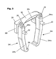
- Figure 3 shows that the Brake bracket above the bolts (pivot bearing) 22 each have a shorter arm 24lo, 24ro than in the lower part (Arms 24lu, 24ru).
- the sections 24lu, 24ru are at their lower end angled inside (towards each other) and wear friction linings there 26th
- the brake brackets 24l, 24r are respectively their brake pads 26 a short distance from the Wheel bridge 18s.
- the brake brackets 24l, 24r are tapered trained and each take a cross pin 28th on, on each of which a bent end of a leaf spring 30 sits positively.
- the leaf spring 30 is in With respect to the wheel 18 convex and dimensioned so that the brake bracket 24l, 24r in the unloaded state at a distance that corresponds to that described above, in which the friction linings 26 in front the opposite surfaces of the wheel land 18s stand.
Abstract
Description
Die Erfindung betrifft eine Transportrolle, wie sie zum Beispiel als Bettenrolle, Apparaterolle, Schwerlastrolle oder dergleichen im privaten und gewerblichen Bereich vielfach Anwendung findet. In der Regel ist die Rolle lenkbar. Eine solche Lenkrolle zeigt die DE 197 24 577 C1.The invention relates to a transport roller, as for Example as bed roll, apparatus roll, heavy duty roll or the like in the private and commercial sector is widely used. As a rule, the role steerable. Such a steering roller is shown in DE 197 24 577 C1.
Die bekannte Lenkrolle weist ein Rad auf, welches an einer Aufnahme drehbar geführt ist.The known castor has a wheel, which a recording is rotatably guided.
An dieser Aufnahme ist auch ein Bremsschuh angeordnet, der über einen Bolzen der Aufnahme gegen die Lauffläche des Rades gedrückt beziehungsweise von der Lauffläche des Rades wieder gelöst werden kann. A brake shoe is also arranged on this mount, the one against the tread with a bolt of the receptacle the wheel pressed or from the tread of the Wheel can be released again.
Je nach Materialart und/oder Materialhärte der Rad-Lauffläche sind unterschiedliche Kräfte notwendig, um eine gewünschte Bremswirkung zu erzielen. Mit zunehmendem Verschleiß der Lauffläche verändert sich die Bremsleistung.Depending on the material type and / or material hardness of the wheel tread different forces are necessary to achieve one to achieve the desired braking effect. With increasing wear The braking performance changes on the tread.
Mit der Erfindung soll eine Transportrolle der eingangs genannten Art mit einer alternativen Bremseinrichtung bereitgestellt werden, wobei die Bremseinrichtung insbesondere unabhängig vom Verschleiß des Rades und unabhängig vom Material der Lauffläche des Rades funktionsbereit sein soll.The invention is intended to be a transport roller at the beginning mentioned type with an alternative braking device are provided, the braking device in particular regardless of the wear of the wheel and independent of the material of the tread of the wheel ready for use should be.
Die Erfindung betrifft in ihrer allgemeinsten Ausführungsform eine Transportrolle mit folgenden Merkmalen:
- einem Rad, das an einer Aufnahme drehbar geführt ist,
- einem ein- oder mehrteiligen Lagerbock, der
- an der Aufnahme befestigt oder Bestandteil der Aufnahme ist,
- zwei Abschnitte des Lagerbocks verlaufen außerhalb des Rades in dessen Umfangsbereich auf gegenüberliegenden Seiten des Rades,
- jeder Abschnitt weist ein Drehlager auf, auf dem ein Bremsbügel geführt wird,
- die Bremsbügel sind an ihrem oberhalb der Drehlager verlaufenden Ende über eine Feder derart verbunden, daß ein Abstand der Bremsbügel an ihren Enden über eine Änderung der Federlänge zwischen Anlenkstellen der Feder an den Bremsbügeln veränderbar ist.
- a wheel that is rotatably guided on a receptacle,
- a one- or multi-part bearing block that
- attached to the receptacle or part of the receptacle,
- two sections of the bearing block run outside the wheel in its circumferential area on opposite sides of the wheel,
- each section has a pivot bearing on which a brake bracket is guided,
- the brake brackets are connected at their end above the pivot bearing via a spring such that a distance between the brake brackets at their ends can be changed by changing the spring length between articulation points of the spring on the brake brackets.
Auf diese Weise wird eine Transportrolle mit einer Bremseinrichtung zur Verfügung gestellt, die nicht auf die Lauffläche des Rades wirkt, sondern auf Seitenflächen des Rades, insbesondere einen Radsteg, das ist der Abschnitt des Rades, der zwischen der Radnabe und der Rad-Lauffläche verläuft und im wesentlichen die Form einer Scheibe mit Mittenbohrung hat.In this way, a transport roller with a braking device provided that are not on the Tread of the wheel acts, but on the side of the Rades, especially a wheel bridge, that's the section of the wheel between the wheel hub and the wheel tread runs and essentially the shape of a Has a disc with a center hole.
Auf diese Weise ist die Bremseinrichtung unabhängig von Art und Material der Lauffläche. Damit ist die Bremseinrichtung auch unabhängig vom Verschleißgrad der Lauffläche.In this way, the braking device is independent of Type and material of the tread. This is the braking device regardless of the degree of wear on the tread.
Ein weiterer Vorteil besteht darin, daß die Bremseinrichtung seitlich auf das Rad wirkt, wo sich üblicherweise weniger Schmutz ansammelt. Der Schmutz wird überwiegend von der Lauffläche aufgenommen und kann bei der hier genannten Transportrolle die Funktionstüchtigkeit der Bremseinrichtung nicht beeinträchtigen.Another advantage is that the braking device acts on the side of the wheel, where is usually less dirt accumulates. The dirt becomes predominant picked up by the tread and can be used in the here Transport role the functionality of the Do not interfere with the braking device.
Ein weiterer wesentlicher Aspekt der Transportrolle ist, daß die zugehörige Bremseinrichtung auch an bestehenden Transportrollen nachgerüstet werden kann.Another key aspect of the transport roll is that the associated braking device also on existing Transport rollers can be retrofitted.
Dies gilt insbesondere dann, wenn die die Bremsbügel beaufschlagende Feder selbst von einem Bolzen beaufschlagt wird, der zum Beispiel bei der Ausführungsform gemäß DE 197 24 577 C1 bereits vorhanden ist und innerhalb einer Lenkrolle unterschiedliche Funktionen erfüllt. This is especially true if the brake bracket acting spring itself acted upon by a bolt that, for example, in the embodiment according to DE 197 24 577 C1 already exists and within a castor fulfills different functions.
Nach einer Ausführungsform verläuft der Lagerbock im wesentlichen parallel zur Radachse oder anders ausgedrückt: senkrecht zur Laufrichtung des Rades. Bei einem einteiligen Lagerbock versteht es sich von selbst, daß er das Rad mit Abstand übergreifen muß. Es ist aber ohne weiteres möglich, den Lagerbock zweiteilig zu gestalten. Vorteilhaft ist, wenn beidseits des Rades jeweils Abschnitte des Lagerbocks vorhanden sind, an denen die Bremsbügel angelenkt werden können.According to one embodiment, the bearing block runs in the essentially parallel to the wheel axis or in other words: perpendicular to the direction of the wheel. At a one-piece bearing block it goes without saying that he the wheel must overlap at a distance. But it is without further possible to design the bearing block in two parts. It is advantageous if sections on both sides of the wheel of the bearing block are present, on which the Brake bracket can be hinged.
Die Bauform bleibt dann klein. Grundsätzlich können die Drehlager für die Bremsbügel auch neben der Lauffläche des Rades ligen. Die Bügel müssen dann jedoch stark gekrümmt sein. Die Abschnitte des Lagerbocks können auch als vertikale Zapfen Bestandteil der Aufnahme für das Rad sein.The design then remains small. Basically, they can Pivot bearing for the brake bracket next to the tread of the Rades leagues. The brackets then have to be strongly curved his. The sections of the pedestal can also be used as vertical Pin be part of the mount for the bike.
Um eine möglichst große Variabilität bezüglich der Bremsleistung zu erreichen, sieht eine Ausführungsform vor, die Bremsbügel so auszubilden, daß ihre vom Rad weg weisenden Arme, in der Regel also die oberhalb der Drehlager verlaufenden Arme kürzer sind als die gegenüberliegenden Arme. Eine solche Ausführungsform wird in der nachfolgenden Figurenbeschreibung näher erläuert.The greatest possible variability in terms of braking performance one embodiment provides train the brake bracket so that its away from the wheel pointing arms, usually those above the pivot bearings running arms are shorter than the opposite Poor. Such an embodiment is in the following description of the figures explained in more detail.
Diese zeigt auch, daß die Bremsbügel baugleich, aber spiegelbildlich innerhalb der Bremseinrichtung angeordnet sein können und an ihrem radseitigen (unteren) Ende in Richtung aufeinander abgewinkelt sind.This also shows that the brake bracket is identical, but arranged in mirror image within the braking device can be and at their wheel-side (lower) end in Are angled towards each other.
Auf diese Weise kann der "Bremsweg" reduziert werden, insbesondere bei Rädern mit relativ breiter Lauffläche und lediglich scheibenartigem Radsteg. In this way the "braking distance" can be reduced especially for bikes with a relatively wide tread and only disc-like wheel bridge.
Dabei können die für die Bremsung wesentlichen Abschnitte der Bremsbügel mit Bremsbelägen (Reibbelägen) ausgebildet sein.The sections essential for braking can the brake bracket is designed with brake pads (friction pads) his.
Während die Drehlager für die Bremsbügel einfache Bolzen sein können, kann die Feder - je nach Anordnung innerhalb der Aufnahme - endseitig auf entsprechende Zapfen der Bremsbügel aufgesteckt oder formschlüssig fixiert werden.While the pivot bearings for the brake bracket are simple bolts can be the spring - depending on the arrangement within the receptacle - at the end on corresponding pins of the Brake brackets can be attached or positively fixed.
Weitere Merkmale der Erfindung sowie die Funktionsweise der beschriebenen Bremseinrichtung ergeben sich aus den Merkmalen der Unteransprüche sowie den weiteren Anmeldungsteilen, insbesondere der nachfolgenden Figurenbeschreibung.Further features of the invention and the mode of operation the braking device described result from the Features of the subclaims and the other parts of the application, especially the following description of the figures.
Dabei wird eine Ausführungsform der Erfindung in verschiedenen Ansichten und Details schematisch dargestellt, und zwar in
- Figur 1:
- eine perspektivische Ansicht, teilweise im Aufriß, einer Transportrolle,
- Figur 2:
- eine perspektivische Teilansicht des Rades ausschließlich mit zugehöriger Bremseinrichtung,
- Figur 3:
- eine perspektivische Einzelansicht der Bremseinrichtung,
- Figur 4:
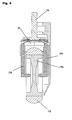
- einen Teilschnitt durch die Transportrolle gemäß Figur 1 im Bereich ihrer Bremsbügel.
- Figure 1:
- a perspective view, partly in elevation, of a transport roller,
- Figure 2:
- a partial perspective view of the wheel exclusively with the associated braking device,
- Figure 3:
- a perspective individual view of the braking device,
- Figure 4:
- a partial section through the transport roller according to Figure 1 in the area of their brake bracket.
Figur 1 zeigt eine Transportrolle mit einer Aufnahme 10,
in der unter anderem ein Zahnkranz 12 geführt ist, der
von einem Bolzen (einer Zahnspindel) 14 durchgriffen
wird. Bestandteil der Aufnahme 10 ist auch eine Welle 16,
auf der ein Lager aufsitzt, welches ein Rad (Laufrad) 18
drehbar führt.FIG. 1 shows a transport roller with a
Das Rad 18 besitzt eine Lauffläche 18f, auf die gemäß
Stand der Technik (DE 197 24 577 C1) ein Bremsschuh
wirkt.The
Die erfindungsgemäße Bremseinrichtung umfaßt dagegen
einen Lagerbock 20, der an der Aufnahme 10 befestigt ist
und sich mit Abstand zur Lauffläche 18f des Rades 18
sowie parallel zur Welle 16 über die Seitenflächen des
Rades 18 hinweg erstreckt, wie die Figuren 1, 2 zeigen.
Die beiden außerhalb des Rades verlaufenden Abschnitte
20l, 20r des Lagerbocks 20 tragen Bolzen 22, die im
wesentlichen horizontal und parallel zu einem die Lauffläche
18f umfangsseitig aufnehmenden Radsteg 18s des
Rades 18 verlaufen.In contrast, the braking device according to the invention comprises
a
Auf den Bolzen 22 sind Bremsbügel 24l, 24r drehbar geführt.
Insbesondere Figur 3 läßt sich entnehmen, daß die
Bremsbügel oberhalb der Bolzen (Drehlager) 22 jeweils
einen kürzeren Arm 24lo, 24ro als im unteren Teil aufweisen
(Arme 24lu, 24ru).
Die Abschnitte 24lu, 24ru sind an ihrem unteren Ende nach innen (aufeinander zu) abgewinkelt und tragen dort Reibbeläge 26. The sections 24lu, 24ru are at their lower end angled inside (towards each other) and wear friction linings there 26th
In der Montageposition, jedoch in ungebremstem Zustand
des Rades 18, liegen die Bremsbügel 24l, 24r beziehungsweise
ihre Bremsbeläge 26 in geringem Abstand vor dem
Radsteg 18s.In the assembly position, but in an unbraked condition
of the
Am gegenüberliegenden Ende, also im Bereich der
Abschnitte 24lo, 24ro sind die Bremsbügel 24l, 24r verjüngt
ausgebildet und nehmen jeweils einen Querstift 28
auf, auf dem jeweils ein umgebogenes Ende einer Blattfeder
30 formschlüssig aufsitzt. Die Blattfeder 30 ist in
Bezug auf das Rad 18 konvex gewölbt und so dimensioniert,
daß sie im unbelasteten Zustand die Bremsbügel 24l, 24r
in einen Abstand hält, der dem zuvor beschriebenen entspricht,
bei dem also die Reibbeläge 26 mit Abstand vor
den gegenüberliegenden Oberflächen des Radsteges 18s
stehen.At the opposite end, i.e. in the area of the
Sections 24lo, 24ro, the
Wird die Feder 30 im Betrieb durch den in Figur 1 dargestellten
Bolzen (die Zahnspindel) 14 belastet (Pfeilrichtung
P in Figur 1), so drückt die Feder 30 die Abschnitte
24lo, 24ro der Bremsbügel 24l, 24r auseinander.
Parallel dazu werden die unteren Abschnitte 24lu, 24ru in
Richtung aufeinander zu bewegt, wobei sie gegen die Oberflächen
des Radsteges 18s geführt werden und das Rad 18
bremsen.Is the
Nach Rückführung des Bolzens 14 wird die Bremsposition
der Bremsbügel 24l, 24r wieder gelöst, da die Blattfeder
30 in ihre unbelastete Ausgangsposition nachgeführt wird
und dabei die Abschnitte 24lo, 24ro wieder aufeinander zu
sowie die Abschnitte 24lu und 24ru wieder voneinander weg
bewegt.After return of the
Claims (11)
- A conveyor roller having the following features:a wheel (18) that is mounted rotatably on a seating position (10),a bracket (20) consisting of a single or multiple components that is attached to the seating position (10) or is a part of the seating position,two sections (20l, 20r) of the bracket (20) run beyond the wheel (18) in the circumference thereof on opposing sides of the wheel (18),each section (20l, 20r) has a pivot bearing (22) on which a braking clip (24l, 24r) is mounted,the ends (24lo, 24ro) of braking clips (24l, 24r) extending above the pivot bearing (22) are connected via a spring (30) in such manner that a distance between the braking clips (24l, 24r) at the ends (24lo, 24ro, 24lu, 24ru) thereof is modifiable by changing the length of the spring between articulation points of the spring (30) on the braking clips (24l, 24r).
- The conveyor roller according to claim 1, the bracket (20) of which extends essentially parallel to the wheel axle and encompasses the wheel (18) with a gap therebetween.
- The conveyor roller according to claim 1, in which the arms (24lo, 24ro) of the braking clips (24l, 24r) that extend above the pivot bearings (22) are shorter than the arms (24ru, 24lu) of the braking clips (24l, 24r) that extend below the pivot bearings (22).
- The conveyor roller according to claim 1, the braking clips (24l, 24r) of which are of identical construction but articulated mirror-inverted about the bracket (20).
- The conveyor roller according to claim 1, the braking clips (24l, 24r) of which are angled towards each other at the ends (24lu, 24ru) thereof extending below the pivot bearings (22).
- The conveyor roller according to claim 1, in which the ends (24lu, 24ru) of the braking clips (24l, 24r) that extend below the pivot bearings are equipped with brake linings (26).
- The conveyor roller according to claim 1, the pivot bearings (22) of which consist of pins whose axes run parallel to the plane of the wheel.
- The conveyor roller according to claim 1, in which the spring (30) is configured as a leaf spring.
- The conveyor roller according to claim 1, in which the end of the spring (30) is bent and supported on corresponding bearing pins (28).
- The conveyor roller according to claim 1, in which the spring (30) can be placed under tension by a bolt (14).
- The conveyor roller according to claim 10, in which the bolt (14) is a component of the seating position (10) on which the wheel (18) is mounted.
Applications Claiming Priority (3)
| Application Number | Priority Date | Filing Date | Title |
|---|---|---|---|
| DE10044370 | 2000-09-08 | ||
| DE10044370A DE10044370C1 (en) | 2000-09-08 | 2000-09-08 | transport roller |
| PCT/DE2001/002946 WO2002020285A1 (en) | 2000-09-08 | 2001-08-01 | Caster |
Publications (2)
| Publication Number | Publication Date |
|---|---|
| EP1315623A1 EP1315623A1 (en) | 2003-06-04 |
| EP1315623B1 true EP1315623B1 (en) | 2004-11-03 |
Family
ID=7655457
Family Applications (1)
| Application Number | Title | Priority Date | Filing Date |
|---|---|---|---|
| EP01957751A Expired - Lifetime EP1315623B1 (en) | 2000-09-08 | 2001-08-01 | Caster |
Country Status (7)
| Country | Link |
|---|---|
| US (1) | US6839938B2 (en) |
| EP (1) | EP1315623B1 (en) |
| JP (1) | JP2004508236A (en) |
| AT (1) | ATE281315T1 (en) |
| AU (1) | AU2001279579A1 (en) |
| DE (2) | DE10044370C1 (en) |
| WO (1) | WO2002020285A1 (en) |
Families Citing this family (14)
| Publication number | Priority date | Publication date | Assignee | Title |
|---|---|---|---|---|
| US6662404B1 (en) * | 2002-08-06 | 2003-12-16 | Kci Licensing, Inc. | High load bearing central-braking caster |
| US8152101B2 (en) * | 2006-09-12 | 2012-04-10 | Law Sondra F | System and method for integrating handicapped accessible seats into aircraft interior configurations |
| US20110119864A1 (en) * | 2008-06-24 | 2011-05-26 | Yazaki Kako Corporation | Brake-equipped caster |
| CA2725826A1 (en) | 2008-07-23 | 2010-01-28 | Yazaki Kako Corporation | Brake-equipped caster |
| JP5215762B2 (en) * | 2008-07-24 | 2013-06-19 | 矢崎化工株式会社 | Caster with brake |
| IT1401138B1 (en) * | 2010-07-23 | 2013-07-12 | O G T M Ohg S R L | WHEEL STRUCTURE WITH LOCKING DEVICE. |
| DE102011017066B4 (en) * | 2011-04-14 | 2013-07-18 | Steinco Paul Vom Stein Gmbh | castor |
| US8365354B1 (en) * | 2011-10-25 | 2013-02-05 | Der Sheng Co., Ltd. | Castor having adjustable braking function |
| CN103057351B (en) * | 2012-12-29 | 2015-04-15 | 胡坚兴 | Braking trundle |
| DE102013007112B4 (en) * | 2013-04-25 | 2019-05-16 | Sew-Eurodrive Gmbh & Co Kg | Handset with roller bearing unit |
| JP2015077907A (en) * | 2013-10-17 | 2015-04-23 | ハンマーキャスター株式会社 | Caster |
| US20190160869A1 (en) * | 2017-11-27 | 2019-05-30 | Ngs Capital Management, Llc | Caster braking system technology |
| US11498360B2 (en) | 2019-05-21 | 2022-11-15 | Ngs Capital Management, Llc | Hybrid bearing arrangement caster technology |
| CN110341635B (en) * | 2019-07-27 | 2022-10-25 | 长春光华学院 | Anticollision structure of AGV dolly |
Family Cites Families (18)
| Publication number | Priority date | Publication date | Assignee | Title |
|---|---|---|---|---|
| US2885720A (en) * | 1955-11-04 | 1959-05-12 | George J Segal | Caster |
| US2942290A (en) * | 1957-05-14 | 1960-06-28 | George J Segal | Self-locking caster |
| GB873107A (en) * | 1958-05-07 | 1961-07-19 | British Castors Ltd | Improvements in or relating to castors |
| US3066764A (en) * | 1959-11-19 | 1962-12-04 | Bassick Co | Caster brake and lock |
| US4128144A (en) * | 1977-12-08 | 1978-12-05 | Vassar Hervey P | Brake and wheel lock |
| JPS5816881Y2 (en) * | 1980-12-25 | 1983-04-05 | コンビ株式会社 | Casters with swing stop mechanism |
| US4494272A (en) * | 1981-07-21 | 1985-01-22 | Natsuo Morita | Reversible caster device having brake mechanism |
| JPS6243304A (en) * | 1985-08-22 | 1987-02-25 | Toshiba Corp | Castor |
| US5236066A (en) * | 1991-05-14 | 1993-08-17 | Neal Daniel M O | Foot operated wheel brake |
| DE9108969U1 (en) * | 1991-07-20 | 1991-09-19 | Kugelfabrik Schulte Gmbh & Co Kg, 5632 Wermelskirchen, De | |
| US5383536A (en) * | 1991-10-29 | 1995-01-24 | Saf-T-Loc, Inc. | Foot actuated wheel brake |
| US5328000A (en) * | 1991-10-29 | 1994-07-12 | Saf-T-Loc, Inc. | Foot actuated wheel brake |
| DE19504074C1 (en) * | 1995-02-08 | 1996-05-02 | Steinco Paul Vom Stein Gmbh | Double castor for furniture, appliances, etc |
| DE19724577C1 (en) * | 1997-06-11 | 1998-12-10 | Rhombus Rollen Gmbh & Co | Castor support wheel |
| US5967535A (en) * | 1997-08-14 | 1999-10-19 | Graco Children's Products Inc. | Swivel wheel mount |
| US6223864B1 (en) * | 1999-05-07 | 2001-05-01 | Margaret Phelps | Foot pressure activated braking wedge, shopping cart wheel restraint |
| US6382364B1 (en) * | 2001-05-15 | 2002-05-07 | Jin Sun Gee Plastics Co., Ltd. | Wheel of a baby walking cart |
| US6662404B1 (en) * | 2002-08-06 | 2003-12-16 | Kci Licensing, Inc. | High load bearing central-braking caster |
-
2000
- 2000-09-08 DE DE10044370A patent/DE10044370C1/en not_active Expired - Fee Related
-
2001
- 2001-08-01 DE DE50104421T patent/DE50104421D1/en not_active Expired - Fee Related
- 2001-08-01 JP JP2002524931A patent/JP2004508236A/en not_active Withdrawn
- 2001-08-01 EP EP01957751A patent/EP1315623B1/en not_active Expired - Lifetime
- 2001-08-01 WO PCT/DE2001/002946 patent/WO2002020285A1/en active IP Right Grant
- 2001-08-01 AU AU2001279579A patent/AU2001279579A1/en not_active Abandoned
- 2001-08-01 US US10/362,547 patent/US6839938B2/en not_active Expired - Fee Related
- 2001-08-01 AT AT01957751T patent/ATE281315T1/en not_active IP Right Cessation
Also Published As
| Publication number | Publication date |
|---|---|
| ATE281315T1 (en) | 2004-11-15 |
| DE50104421D1 (en) | 2004-12-09 |
| AU2001279579A1 (en) | 2002-03-22 |
| WO2002020285A1 (en) | 2002-03-14 |
| US20030163892A1 (en) | 2003-09-04 |
| US6839938B2 (en) | 2005-01-11 |
| DE10044370C1 (en) | 2002-05-02 |
| EP1315623A1 (en) | 2003-06-04 |
| JP2004508236A (en) | 2004-03-18 |
Similar Documents
| Publication | Publication Date | Title |
|---|---|---|
| EP1315623B1 (en) | Caster | |
| EP0553105B1 (en) | Disc brake for vehicles, especially road vehicles | |
| EP0759392B1 (en) | Roller for endless tracks | |
| EP0148468B1 (en) | Rotor for open-end spinning | |
| EP0555682B1 (en) | Rotary drive for a vehicle disc brake adjusting spindle | |
| DE19781811B4 (en) | Tracking kit for a conveyor belt | |
| DE20103173U1 (en) | Roller skate with retractable undercarriage | |
| EP1527993A1 (en) | Conveyor system for an aircraft cargo hold | |
| DE1292524B (en) | Parking facility for motor vehicles | |
| EP3253985B1 (en) | Disk brake for a utility-vehicle wheel | |
| DE3421413C2 (en) | ||
| DE2017831C2 (en) | Support for a rotary kiln | |
| DE4135565C2 (en) | Accumulation roller for accumulation roller conveyors | |
| DE3308499C2 (en) | Brake caliper for a disc brake | |
| DE102007031237A1 (en) | Tilt-angle-controlled rolling device with staggered rollers | |
| EP0248996B1 (en) | Tandem-axle unit | |
| DE4402960A1 (en) | Disc brake | |
| DE60213220T3 (en) | disc brake | |
| DE19832637C2 (en) | Crawler track | |
| DE2904957A1 (en) | Tool for truing surface of brake disc - has cutting head fitted in place of brake pad and pressed against disc | |
| WO1984003338A1 (en) | Disk brake for vehicles, with reduced lining | |
| DE4333518A1 (en) | Curved belt conveyor | |
| DE461020C (en) | Internal brake for motor vehicles | |
| DE2208251C3 (en) | Disc brake for rail vehicles | |
| EP1314463A1 (en) | Inline rollerskate with quick release wheel fastening system |
Legal Events
| Date | Code | Title | Description |
|---|---|---|---|
| PUAI | Public reference made under article 153(3) epc to a published international application that has entered the european phase |
Free format text: ORIGINAL CODE: 0009012 |
|
| 17P | Request for examination filed |
Effective date: 20030211 |
|
| AK | Designated contracting states |
Designated state(s): AT BE CH CY DE DK ES FI FR GB GR IE IT LI LU MC NL PT SE TR |
|
| AX | Request for extension of the european patent |
Extension state: AL LT LV MK RO SI |
|
| GRAP | Despatch of communication of intention to grant a patent |
Free format text: ORIGINAL CODE: EPIDOSNIGR1 |
|
| GRAS | Grant fee paid |
Free format text: ORIGINAL CODE: EPIDOSNIGR3 |
|
| GRAA | (expected) grant |
Free format text: ORIGINAL CODE: 0009210 |
|
| AK | Designated contracting states |
Kind code of ref document: B1 Designated state(s): AT BE CH CY DE DK ES FI FR GB GR IE IT LI LU MC NL PT SE TR |
|
| PG25 | Lapsed in a contracting state [announced via postgrant information from national office to epo] |
Ref country code: TR Free format text: LAPSE BECAUSE OF FAILURE TO SUBMIT A TRANSLATION OF THE DESCRIPTION OR TO PAY THE FEE WITHIN THE PRESCRIBED TIME-LIMIT Effective date: 20041103 Ref country code: FI Free format text: LAPSE BECAUSE OF FAILURE TO SUBMIT A TRANSLATION OF THE DESCRIPTION OR TO PAY THE FEE WITHIN THE PRESCRIBED TIME-LIMIT Effective date: 20041103 Ref country code: NL Free format text: LAPSE BECAUSE OF FAILURE TO SUBMIT A TRANSLATION OF THE DESCRIPTION OR TO PAY THE FEE WITHIN THE PRESCRIBED TIME-LIMIT Effective date: 20041103 |
|
| REG | Reference to a national code |
Ref country code: GB Ref legal event code: FG4D Free format text: NOT ENGLISH |
|
| REG | Reference to a national code |
Ref country code: CH Ref legal event code: EP |
|
| REF | Corresponds to: |
Ref document number: 50104421 Country of ref document: DE Date of ref document: 20041209 Kind code of ref document: P |
|
| REG | Reference to a national code |
Ref country code: IE Ref legal event code: FG4D Free format text: GERMAN |
|
| PG25 | Lapsed in a contracting state [announced via postgrant information from national office to epo] |
Ref country code: GR Free format text: LAPSE BECAUSE OF FAILURE TO SUBMIT A TRANSLATION OF THE DESCRIPTION OR TO PAY THE FEE WITHIN THE PRESCRIBED TIME-LIMIT Effective date: 20050203 Ref country code: DK Free format text: LAPSE BECAUSE OF FAILURE TO SUBMIT A TRANSLATION OF THE DESCRIPTION OR TO PAY THE FEE WITHIN THE PRESCRIBED TIME-LIMIT Effective date: 20050203 Ref country code: SE Free format text: LAPSE BECAUSE OF FAILURE TO SUBMIT A TRANSLATION OF THE DESCRIPTION OR TO PAY THE FEE WITHIN THE PRESCRIBED TIME-LIMIT Effective date: 20050203 |
|
| PG25 | Lapsed in a contracting state [announced via postgrant information from national office to epo] |
Ref country code: ES Free format text: LAPSE BECAUSE OF FAILURE TO SUBMIT A TRANSLATION OF THE DESCRIPTION OR TO PAY THE FEE WITHIN THE PRESCRIBED TIME-LIMIT Effective date: 20050214 |
|
| GBT | Gb: translation of ep patent filed (gb section 77(6)(a)/1977) |
Effective date: 20050310 |
|
| NLV1 | Nl: lapsed or annulled due to failure to fulfill the requirements of art. 29p and 29m of the patents act | ||
| PG25 | Lapsed in a contracting state [announced via postgrant information from national office to epo] |
Ref country code: CY Free format text: LAPSE BECAUSE OF FAILURE TO SUBMIT A TRANSLATION OF THE DESCRIPTION OR TO PAY THE FEE WITHIN THE PRESCRIBED TIME-LIMIT Effective date: 20050801 Ref country code: AT Free format text: LAPSE BECAUSE OF NON-PAYMENT OF DUE FEES Effective date: 20050801 Ref country code: LU Free format text: LAPSE BECAUSE OF NON-PAYMENT OF DUE FEES Effective date: 20050801 |
|
| PG25 | Lapsed in a contracting state [announced via postgrant information from national office to epo] |
Ref country code: BE Free format text: LAPSE BECAUSE OF NON-PAYMENT OF DUE FEES Effective date: 20050831 Ref country code: CH Free format text: LAPSE BECAUSE OF NON-PAYMENT OF DUE FEES Effective date: 20050831 Ref country code: MC Free format text: LAPSE BECAUSE OF NON-PAYMENT OF DUE FEES Effective date: 20050831 Ref country code: LI Free format text: LAPSE BECAUSE OF NON-PAYMENT OF DUE FEES Effective date: 20050831 |
|
| PLBE | No opposition filed within time limit |
Free format text: ORIGINAL CODE: 0009261 |
|
| STAA | Information on the status of an ep patent application or granted ep patent |
Free format text: STATUS: NO OPPOSITION FILED WITHIN TIME LIMIT |
|
| 26N | No opposition filed |
Effective date: 20050804 |
|
| ET | Fr: translation filed | ||
| REG | Reference to a national code |
Ref country code: CH Ref legal event code: PL |
|
| BERE | Be: lapsed |
Owner name: *RHOMBUS ROLLEN G.M.B.H. & CO. Effective date: 20050831 |
|
| PG25 | Lapsed in a contracting state [announced via postgrant information from national office to epo] |
Ref country code: PT Free format text: LAPSE BECAUSE OF NON-PAYMENT OF DUE FEES Effective date: 20050403 |
|
| PGFP | Annual fee paid to national office [announced via postgrant information from national office to epo] |
Ref country code: DE Payment date: 20080710 Year of fee payment: 8 |
|
| PGFP | Annual fee paid to national office [announced via postgrant information from national office to epo] |
Ref country code: FR Payment date: 20080818 Year of fee payment: 8 Ref country code: IE Payment date: 20080819 Year of fee payment: 8 Ref country code: IT Payment date: 20080825 Year of fee payment: 8 |
|
| PGFP | Annual fee paid to national office [announced via postgrant information from national office to epo] |
Ref country code: GB Payment date: 20080822 Year of fee payment: 8 |
|
| GBPC | Gb: european patent ceased through non-payment of renewal fee |
Effective date: 20090801 |
|
| REG | Reference to a national code |
Ref country code: FR Ref legal event code: ST Effective date: 20100430 |
|
| REG | Reference to a national code |
Ref country code: IE Ref legal event code: MM4A |
|
| PG25 | Lapsed in a contracting state [announced via postgrant information from national office to epo] |
Ref country code: FR Free format text: LAPSE BECAUSE OF NON-PAYMENT OF DUE FEES Effective date: 20090831 Ref country code: DE Free format text: LAPSE BECAUSE OF NON-PAYMENT OF DUE FEES Effective date: 20100302 Ref country code: IE Free format text: LAPSE BECAUSE OF NON-PAYMENT OF DUE FEES Effective date: 20090803 |
|
| PG25 | Lapsed in a contracting state [announced via postgrant information from national office to epo] |
Ref country code: GB Free format text: LAPSE BECAUSE OF NON-PAYMENT OF DUE FEES Effective date: 20090801 |
|
| PG25 | Lapsed in a contracting state [announced via postgrant information from national office to epo] |
Ref country code: IT Free format text: LAPSE BECAUSE OF NON-PAYMENT OF DUE FEES Effective date: 20090801 |