EP1315552B1 - Method and apparatus for improving efficiency of a reverse osmosis system - Google Patents
Method and apparatus for improving efficiency of a reverse osmosis system Download PDFInfo
- Publication number
- EP1315552B1 EP1315552B1 EP00957275A EP00957275A EP1315552B1 EP 1315552 B1 EP1315552 B1 EP 1315552B1 EP 00957275 A EP00957275 A EP 00957275A EP 00957275 A EP00957275 A EP 00957275A EP 1315552 B1 EP1315552 B1 EP 1315552B1
- Authority
- EP
- European Patent Office
- Prior art keywords
- water
- reverse osmosis
- membrane chamber
- pressure
- pump
- Prior art date
- Legal status (The legal status is an assumption and is not a legal conclusion. Google has not performed a legal analysis and makes no representation as to the accuracy of the status listed.)
- Expired - Lifetime
Links
Images


Classifications
-
- Y—GENERAL TAGGING OF NEW TECHNOLOGICAL DEVELOPMENTS; GENERAL TAGGING OF CROSS-SECTIONAL TECHNOLOGIES SPANNING OVER SEVERAL SECTIONS OF THE IPC; TECHNICAL SUBJECTS COVERED BY FORMER USPC CROSS-REFERENCE ART COLLECTIONS [XRACs] AND DIGESTS
- Y02—TECHNOLOGIES OR APPLICATIONS FOR MITIGATION OR ADAPTATION AGAINST CLIMATE CHANGE
- Y02A—TECHNOLOGIES FOR ADAPTATION TO CLIMATE CHANGE
- Y02A20/00—Water conservation; Efficient water supply; Efficient water use
- Y02A20/124—Water desalination
- Y02A20/131—Reverse-osmosis
Definitions
- the invention relates to a new and useful power recovery system to reduce the energy requirements of many industrial and liquid purification processes that involve pumping liquid or gases at high pressures.
- This invention is particularly well-suited for use in reverse osmosis processes which are used to remove salt from sea water.
- a liquid or gas is pumped at high pressure into a chamber.
- a portion of the liquid or gas is purified or otherwise processed and drawn from the chamber.
- the remainder of the high pressure gas or liquid is discharged from the chamber as reject that is disposed.
- the reject is usually at a very high pressure and this pressure must be dissipated through the use of a throttling valve or other device.
- the throttling valve reduces the pressure in the reject stream to essentially 0 psi so that all of the pressure energy in the reject stream is dissipated and provides no further benefit to the process.
- a reverse osmosis water purification system comprising:
- the purification membrane chamber having an inlet connected to the pump end of the hydraulic turbocharger is a second purification membrane chamger; a first purification membrane chamber has an inlet operatively connected to the feed pump for receiving a supply of high pressure unpurified water from the free pump for receiving a supply of high pressure unpurified water from the fee pump, the first purification membrane chamber having an outlet for discharging water purified in the first purification membrane chamber, and the first purification membrane chamber having a discharge opening for discharging high pressure unpurified water from the first purification membrane chamber; and the pump end of the hydraulic turbocharger has an inlet for receiving the high pressure unpurified water from the first purification member chamber.
- the inlet of the pump end of the hydraulic turbocharger receives a supply of unpurified water from the feed pump.
- the present invention is an improvement over U.S. Patent No. 4,983,305 which was invented by the inventor herein.
- the 305' Patent describes the use of a hydraulic turbocharger to provide a pressure boost to a brine steam of a two stage reverse osmosis system having at least two purification membrane chambers.
- the flow and pressure which energized the turbine section of the turbocharger was the reject (brine) of the second stage.
- brine reject
- Increasing the pressure between the first and second stages provided several advantages.
- the boost pressure increased the water production of the second stage.
- high pressure is required to match the increased osmotic pressure due to the higher salinity of the second stage feed water.
- the boost pressure substantially balanced the flux rate between the first and second stage membrane, thereby preventing damaging over-production of the first stage membrane.
- the increased flow velocity decreased the polarization of the water layer at the membrane surface which also increased production of the purified product water.
- the higher pressure and velocity of the interstage boosted system also resulted in lower total dissolved solids of the product water.
- the energy necessary to provide the pressure boost was recovered energy from the second stage brine, making this type of reverse osmosis system the most energy efficient on a kw/gal. basis.
- Reverse osmosis water desalination systems are usually designed to produce a constant flow of permeate, or product water. This measurement of the constant flow is the basis for rating and selling a system. However, this desired constant output is subjected to variable inputs such as temperature and salinity changes and membrane aging. These variables require that the reverse osmosis system operate through a range of flow and pressure conditions.
- the method of controlling a reverse osmosis system to achieve constant product water output with variable feed water inputs and membrane conditions is another object of the invention.
- the invention is directed to a multiple stage reverse osmosis system that can be utilized to reduce the energy requirements of many industrial and liquid purification processes which involve pumping liquid or gases at high pressures. More particularly, the multiple stage reverse osmosis system recovers energy from the high pressure liquid or gas that is discharged from the purification process and uses this energy to pump the liquid or gas at high pressure into the purification process.
- the reverse osmosis system of the present invention is particularly well-suited for use in a process to remove salt from sea water. It should be understood, however, that the multiple stage reverse osmosis system of the present invention can be used to reduce the energy requirements of many industrial and liquid purification processes that involve pumping liquid or gases at high pressures.
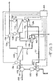
- Fig. 1 shows a typical reverse osmosis system 1 where saltwater passes through an inlet pipe 3 into a booster pump 5.
- the booster pump increases the pressure of the saltwater to about 25 pounds per square inch and pumps the saltwater through a filter 7 where suspended impurities in the saltwater can be removed. From the filter, 7 the saltwater passes into feed pump 9 where the pressure of the saltwater is increased to about 69 bar (1000 psi).
- the high pressure (69 bar (1000 psi)) saltwater is then directed into a membrane chamber 11 where salt is removed from at least a portion of the sea water.
- a membrane chamber 11 where salt is removed from at least a portion of the sea water.
- 379 L/min (100 gallons per minute) of saltwater is supplied to the membrane chamber 11, approximately 95 L/min (25 gallons per minute) of purified water will be produced by the membrane chamber.
- the purified water is discharged from the membrane chamber at a low pressure through the fresh water discharge line 13.
- Approximately 284 L/min (75 gallons per minute) of concentrated saltwater brine is discharged from the membrane chamber through the brine discharge line 15.
- the concentrated brine is discharged from the chamber at about 66 bar (950 psi) and this concentrated brine is called the reject.
- the high pressure reject passes through a throttle valve 17 where the pressure of the concentrated brine reject is reduced so that the reject can be discharged through a waste line 19 for disposal.
- the pressure of the reject discharged through the waste line 19 is essentially 0 bar (0 psi).
- the throttle valve 17 also acts to maintain pressure in the brine discharge line 15 to maintain the proper pressure in the membrane chamber to allow at least a portion of the saltwater to be purified.
- the throttle valve lowers the pressure of the concentrated brine reject stream by approximately 66 bar (950 psi).
- the hydraulic power dissipated by the throttle valve is about 31 kW (42 horsepower). This is a great deal of energy that must be put into the system by the feed pump 9 and this energy is effectively lost from the system as the energy is dissipated by the throttle valve 17.
- Fig. 2 shows the reverse osmosis system described in U.S. Patent Nos. 4,966,708 , 4,983,305 and 5,049,045 where a power recovery pump turbine has been installed in the system.
- This system has essentially the same components as the previously described reverse osmosis system shown in Fig. 1 with the exception that a power recovery pump turbine 25 is operatively connected between the feed pump 9 and the membrane chamber 11 and the power recovery pump turbine 25 is operatively connected to the brine discharge line 15 from the membrane chamber 11.
- the power recovery pump turbine 25 has a turbine end 27 and a pump end 29.
- a pipe 31 from the feed pump 9 is connected to a pump inlet 33 on the pump end 29.
- the sea water passes through the pump inlet 33 through the pump end 29 and is discharged from the pump discharge 35. From the pump discharge 35 the sea water passes through pipe 37 into the membrane chamber 11. The portion of the sea water that is purified by the membrane chamber 11 passes from the chamber through discharge line 13. The concentrated brine reject passes from the membrane chamber 11 through brine discharge line 15. Brine discharge line 15 is operatively connected to a turbine inlet nozzle 41 on the turbine end 27 of the power recovery pump turbine 25. The reject passes through the turbine end 27 and is discharged from the turbine exhaust passage 43. From the turbine exhaust passage 43 the reject passes through waste line 45 and is disposed.
- the use of the power recovery pump turbine greatly reduces the pressure increase in the saltwater required to be produced by the feed pump 9 and this significantly reduces the power requirements for the feed pump. Reducing the power requirement for the feed pump has a significant impact on the energy cost for operating the feed pump 9. At the same time the reduced feed pump discharge pressure reduces the stress on the pump and should extend the life of the feed pump.
- the concentrated saltwater brine that is discharged through the turbine exhaust passage is at a very low or zero pressure so that the concentrated saltwater brine can be easily disposed of. This eliminates the need for a throttle valve to reduce the pressure of the concentrated saltwater brine that is discharged from the membrane chamber 11.
- the rate of the permeate production is regulated by controlling the membrane pressure and the rate of feed flow. Normally this regulation is done with a series of valves which must be adjusted by an operator or a computer system in response to changes in the permeate output and quality.
- the output of permeate may change for several reasons such as changes in the salinity of the water or the temperature of the water in the feed stream. It is also possible for the membrane to compact after years of use and a compaction of the membrane can also affect the output of permeate.
- a reverse osmosis system if the temperature of the sea water decreases, it decreases the effectiveness of the membrane chamber and, for a given membrane pressure and feed flow rate, the output of permeate decreases. Conversely, if the temperature of the saltwater increases, the membrane chamber becomes more permeable and the output of permeate increases.
- the membrane pressure In order to prevent excessive permeate output with warm feed water and insufficient permeate output with cold feed water, the membrane pressure must be actively controlled.
- the valving arrangements utilized in the past require personal attention that is expensive and not always available. Thus, it would be desirable to have a mechanism where the membrane pressure is controlled under changing conditions to produce the desired amount of permeate.
- the multiple stage reverse osmosis system of the present invention can be utilized to control the membrane pressure to produce the desired quantity of permeate.
- the multiple stage reverse osmosis system affects the membrane pressure in two ways: by the amount of boost developed by the pump and by the amount of flow resistance created in the reject line. Focusing on the amount of resistance in the reject line, the multiple stage reverse osmosis system has a unique pressure versus flow relationship ideally suited for reverse osmosis systems. To appreciate the advantages of the multiple stage reverse osmosis system it is helpful to compare this device with conventional ways of controlling membrane pressure. In a normal reverse osmosis system a valve or orifice plate is normally used to control the membrane pressure.
- the valve or orifice plate creates a flow resistance on the reject line and the valve or orifice plate has a generally square relationship between the membrane pressure and the flow rate. That is, if the flow rate is halved the pressure resistance decreases to one-fourth. In a reverse osmosis system, if the feed temperature increases then the reject flow decreases as more sea water passes through the membrane chamber and becomes permeate. This results in a lower reject flow which reduces the pressure resistance of the valve; however, the reduction is not enough to reduce the membrane pressure and to reduce the production rate of permeate. Therefore, the valve on the reject line must be manually opened or adjusted to obtain the desired membrane pressure to adjust the production rate of the permeate.
- the multiple stage reverse osmosis system of the present invention has a different pressure versus flow characteristic that is particularly well-suited for a reverse osmosis system. Specifically, cutting the reject flowing in half results in the pressure resistance decreasing to one-fifth of its former value rather than one-fourth as with a valve or orifice place.
- the somewhat lower membrane pressure is, in many cases, sufficient to prevent excess permeate output. For example, if the temperature of the feed water decreases, the flow rate through the reject line increases since less permeate is being produced.
- the multiple stage reverse osmosis systems will then produce a flow resistance in the reject line that is greater than the pressure increase caused by a valve or orifice plate.
- the result is that the permeate production does not drop off as much as with a valve or orifice plate.
- the net effect of using the multiple stage reverse osmosis system is that it reduces over-production of permeate when the feed water temperature increases and minimizes under-production of permeate when the feed water temperature drops. This is done without the intervention by an operator or any auxiliary control system.
- the same permeate regulation also occurs when the feed water ability or membrane compaction changes.
- Fig. 3 show a multiple stage reverse osmosis system where a power recovery pump turbine and an impulse turbine have been installed in the system.
- Saltwater passes through an inlet pipe 100 into a centrifugal pump 101 which is a high pressure feed pump.
- the centrifugal pump 101 is driven by an electric motor 102.
- the electric motor 102 is operatively connected to an impulse turbine 103.
- the centrifugal pump 101 is in communication with a first stage reverse osmosis membrane chamber 104 through a feed pipe 105 and through a control valve 120.
- the high pressure saltwater is directed into the membrane chamber 104 where salt is removed from at least a portion of the sea water.
- the purified water is discharged from the membrane chamber 104 at a low pressure through a fresh water discharge line 106.
- the concentrated brine is discharged from the membrane chamber 104 through a discharge pipe 107.
- a hydraulic power recovery pump turbine or turbocharger 108 as described in U.S. Patent Nos. '708, '305 and '045, as discussed above, is in communication with the discharge piping 107.
- the turbocharger 108 has a turbine end T and a pump end P.
- the discharge pipe 107 from the first membrane chamber 104 is connected to the pump end P.
- the reject or brine water passes through the pump end P and is discharged from the turbocharger 108 into a first and second brine piping 110.
- the piping 110 is operatively connected to a second reverse osmosis membrane chamber 112 where additional salt is removed from the water.
- the purified water is discharged from the second membrane chamber 112 through a fresh water discharge piping 114.
- the piping 114 is in communication with the product water piping 106 from the first membrane chamber 104.
- High pressure concentrated saltwater brine is discharged from the membrane chamber 112 through a second stage brine piping 116.
- the second stage brine piping 116 is operatively connected to the turbine end T of the hydraulic turbocharger 108.
- a branch 121 extends off the second stage brine piping 116 and is in communication with an impulse turbine inlet needle valve 122.
- a control valve 124 is located on the brine branch piping 121 between the second stage brine piping 116 and the turbine inlet needle valve 122.
- the impulse turbine inlet needle valve 122 is operatively connected to the impulse turbine 103.
- Additional control instrumentation and valves can be located in the system.
- a product flow meter 130 is positioned on the first stage product water piping 106.
- a second product flow meter 132 is positioned on the second stage product water piping 114.
- a brine flow meter 134 is positioned on the second stage brine piping 116.
- a pressure gauge 136 is operatively connected adjacent the first stage membrane chamber 104 to measure the first stage feed pressure as the water leaves the centrifugal pump 101 and enters the membrane chamber 104.
- a pressure gauge 138 is positioned on the hydraulic turbocharger pump side of the membrane chamber 112 to monitor the pressure in the first and second brine piping 110.
- a hydraulic turbocharger auxiliary nozzle valve 140 is operatively connected to the turbocharger end T of the turbocharger 108.
- An additional throttling valve 142 can be operatively positioned on the first and second brine piping 110 between the pump end P of the turbocharger 108 and the second stage reverse osmosis membrane chamber 112.
- a programmable logic controller 144 is used to control valve 120, the impulse turbine inlet needle valve 122, the second stage brine by-pass valve 124, the auxiliary nozzle valve 140, and the second stage flow control valve 142.
- the product flow meter 130, the product flow meter 132, the pressure gauge 136, the pressure gauge 138, and the brine flow meter 134 all provide input signals to the controller 144.
- this invention can be applied to a three stage reverse osmosis system with minor modifications and may also be applied to lower pressure reverse osmosis plants under various circumstances and to other reverse osmosis industrial processes.
- the two stage reverse osmosis system is pressurized by a centrifugal pump 101 which can be modified to use a positive displacement pump by eliminating the flow control valve 120.
- saltwater, or feed water enters from a pretreatment system (not shown) through piping 100 into the high pressure centrifugal pump 101.
- the pressure of the water is raised to an operating pressure of the first stage reverse osmosis membrane chamber 104, which in this example would be approximately 62 bar (900 psi).
- the feed water enters the reverse osmosis chamber 104 where a portion of the feed water is purified by the reverse osmosis membrane, rejecting salt passage through the membrane. In this example the portion of the feed water purified is approximately 40% of the total feed flow. This purified water is called the "permeate" or "product water”.
- the permeate leaves the reverse osmosis membrane chamber 104 through the first stage pipe water piping 106 at a low pressure of about 0,7 to 1,4 bar (10 to 20 psi).
- the remainder of the feed water is now increased concentrated brine or reject and leaves the reverse osmosis membrane chamber 104 through the first brine piping 107 at a pressure of about 55 bar (880 psi).
- the brine water enters the turbocharger 108 at the pump end P where the pressure is increased to about 82 to 90 bar (1200 to 1300 psi).
- the higher pressure is desired in order to overcome the higher osmotic pressure of the brine or reject water.
- the pump end P of the turbocharger 108 passes the increase pressure brine through the first and second stage brine piping 110 into the second stage reverse osmosis membrane chamber 112. About 30% of the brine feed is purified into product water and is discharged from the second stage membrane chamber 112 through the second stage product water piping 114. The remaining 70% of the brine feed is concentrated to an even higher level of dissolved solids.
- the second stage brine is discharged from the second stage reverse osmosis chamber 112 through the second stage brine piping 116 at a pressure of about 80 to about 86 bar (about 1150 to about 1250 psi) and enters the turbine end T of the turbocharger 108.
- the high pressure brine energy is converted by the turbine end T of the turbocharger into mechanical shaft energy which in turn drives the pump end P of the turbocharger 108, thereby accounting for the pressure boost of the feed water.
- the present invention avoids this energy loss by incorporating another type of turbine in this system.
- the impulse turbine 103 is mechanically coupled to the drive motor 102 and is in hydraulic communication with the branch 121 of the second stage brine piping 116 which is upstream of the turbocharger 108. Any excess brine flow from the second stage reverse osmosis membrane chamber 112 which is not required by the turbocharger 108 is used by the impulse turbine 103 to unload, or supply power to the high pressure pump drive motor 102.
- the brine flow to the impulse turbine can widely vary due to the changing requirements of the turbocharger 108 as the turbocharger 108 responds to the input variability of feed water conditions and membrane conditions.
- P B2 second stage brine pressure in psi.
- P E hydraulic turbocharger exhaust pressure in psi.
- P BRQUB pressure boost required to meet second stage conditions in psi.
- P BABL boost pressure available if all brine is routed to hydraulic turbocharger and is used to boost second stage pressure in psi.
- Q EX excess bring flow in GPM that is not required by hydraulic turbocharger to meet second stage membrane pressure requirements.
- IT H impulse turbine horse power.
- R BRQUD P BRQUD / P B ⁇ 2 N
- EX Q B ⁇ 2 - R
- Q EX 528.4 - 0.454545 792.5
- Q EX 528.4 - 360.2269
- first stage brine flow (column 1, which is also the second stage feed flow) ranges from 2400 to 2998 L/min (634 to 792 gpm); the second stage brine flow (column 3) ranges from 1798 to 1999 L/ min (475 to 528 gpm); the second stage membrane operating pressure (column 2) ranges from 77 to 90 bar (1116 to 1305 psi); and desired turbo pressure boosts (column 6) are 9, 14, 22, and 27 bar (130, 203, 319, and 391 psi).
- Columns 4 and 5 are second stage brine pressure and turbocharger exhaust pressure, respectively.
- Cases 1 and 2 show cold feed water conditions, while Cases 3 and 4 show warmer feed water conditions.
- the colder feed water requires higher operating pressures and produces more brine from the first stage.
- the opposite is true for the warmer feed conditions.
- Salinity changes also causes similar affects; i.e., higher salinity causes higher pressures and higher reject ratio (proportion of brine flow divided by total flow).
- the control system must maintain the desired constant product flow at an acceptable water quality (where total dissolved solids level is below 500 ppm), utilizing the least amount of energy while input feed conditions are varying over a range of values.
- the system uses the centrifugal high pressure feed pump 101 and the flow control valve 120.
- Case 2 as an initial condition and proceeding to case 3, the following sequence of events will happen.
- the first stage membrane chamber 104 response will be to over produce permeate. This over production is damaging to the membrane and also reduces water quality, that is increased total dissolved solids.
- the first stage membrane pressure should be reduced.
- the product flow member's 130 signal to the controller 144 will cause the controller 144 to close the feed throttle valve 120, thereby decreasing feed flow to the first stage membrane chamber 104.
- the second stage brine bypass valve 124 will be opened to allow greater flow, which, in turn, reduces the system pressure resistance.
- the interstage brine flow is reduced from 2998 to 2400 L/min (792 to 634 gpm).
- the second stage membrane pressure requirement has been reduced from 90 to 77 bar (1305 to 1116 psi) and second stage brine flow has been reduced from 1999 to 1798 L/min (528 to 475 gpm)
- controller 144 must open by-pass valve 124 until the desired point is obtained.
- By-pass flow to the impulse turbine 103 increases from 635 to 996 L/min (168 to 263 gpm).
- Impulse turbine power output likewise increases from 79 to 107 kW (106 to 144 hp).
- the controller 144 signals the variable are nozzle 122 on the impulse turbine 103 to open to accommodate the increased flow.
- Fig. 4 shows another multiple stage reverse osmosis system of the present invention which also utilizes a first stage membrane chamber 104, a second stage member membrane 112, and a turbocharger 108, as shown in Fig. 3 . Since the arrangement of the chambers and the plumbing connections for the various membrane chambers are essentially the same as previously described for Fig. 3 , the description will not be repeated. The difference between the system shown in Fig. 3 and the system of Fig. 4 is that a reverse running pump turbine 153 is used in place of the impulse turbine 103. The reverse running pump turbine 153 can operate either in parallel, as shown in Fig. 4 , or in series, as shown in Fig. 5 , with the turbocharger 108.
- Fig. 5 which shows a series configuration, where use of the reverse running pump turbine 153 relies on the throttle flow valve 122, which is operatively connected between the turbine exhaust end of the hydraulic turbocharger and the reverse running pump turbine 153.
- the series configuration shown in Fig. 5 further includes a second by-pass valve 155 which is operatively connected to the branch 121 of the second phase piping between the by-pass flow valve 124 and the impulse turbine inlet needle valve 122.
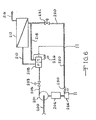
- Fig. 6 shows a further embodiment of the present invention using two different energy recovery turbines and a control valve to maximize energy efficiency of a reverse osmosis system.
- Fig. 6 shows an inlet pipe 200 operatively connected to a high pressure pump 201.
- An electric drive motor 202 is connected to the high pressure pump 201 and is in hydraulic communication through a pipe 205 with a feed control valve 203.
- the feed control valve 203 is in communication with a hydraulic turbocharger 208.
- the hydraulic turbocharger 208 is in communication through a piping 210 with a reverse osmosis membrane chamber 212.
- the turbocharger 208 has a pump end P and a turbine end T. Purified waters are discharged from the reverse osmosis membrane chamber 212 through a piping 216. Brine or reject is discharged from the reverse osmosis membrane chamber 212 through a piping 218. The brine piping 218 is operatively connected to the turbine end T of the turbocharger 208. A pipe 220 branches off the pipe 218 and communicates with an impulse turbine engine 224. In this embodiment it is shown that the turbocharger 208 has a turbocharger auxiliary valve 226.
- variable area needle valve 230 is operatively connected to the brine side of the reverse osmosis membrane chamber 212 by the branch 220.
- the variable area needle valve 230 converts and controls the pressure energy of the brine stream into the high velocity jet required by the impulse turbine 224.
- an additional valve 232 can be positioned between the variable area needle valve 230 and the brine side of the reverse osmosis membrane chamber 212 to provide either equipment isolation or additional control of the system.
- An initial operating condition for a reverse osmosis system has a 3785 L/min (1000 gpm) feed flow, 3028 L/min (800 psi) membrane pressure, 55 bar (600 gpm) brine flow, and 2839 L/min (750 psi) brine pressure.
- the final end of membrane life condition is 3785 L/min (1000 gpm) feed flow, 65 bar (1000 psi) membrane pressure, 2271 L/min (600 gpm) brine flow, and 66 bar (950 psi) brine pressure.
- a properly sized feed pump for this system with the turbocharger 208 would have a capacity of 3785 L/min (1000 gpm) at a differential pressure of 44 bar (640 psi).
- the pump discharge pressure is sized for the highest anticipated pressure required, which is 44 bar (640 psi).
- the pressure boost provided by the turbocharger at the 69 bar (1000 psi) condition will be about 25 bar (360 psi).
- the turbo boost will be 20 bar (288 psi). This means that the required pump discharge pressure at the 55 bar (800 psi) condition is 35 bar (512 psi).
- 88 bar (128 psi) of pressure is being throttled in the flow control valve.
- brine flow is diverted from the turbocharger to a level that allows the turbo to produce a 11 bar (160 psi) pressure boost.
- the diverted flow is admitted to the nozzle valve 230 of the impulse turbine 224.
- the amount of brine required by the turbocharger 208 is approximately 1419 L/min (375 gpm).
- the other 851 L/min (225 gpm) is available to the impulse turbine 224 and represents, at a turbine efficiency of 0.85, an additional 62 kW (83 hp) of recovered energy.
- the variable area nozzle 230 of the impulse turbine 224 will be closed thereby making available to the turbocharger 208 the necessary brine water for achieving the proper pressure.
- the impulse type turbine has the best variable capacity performance and so is the most suited for this system.
Landscapes
- Separation Using Semi-Permeable Membranes (AREA)
Applications Claiming Priority (1)
| Application Number | Priority Date | Filing Date | Title |
|---|---|---|---|
| PCT/US2000/020896 WO2002009855A1 (en) | 1999-03-19 | 2000-07-31 | Method and apparatus for improving efficiency of a reverse osmosis system |
Publications (3)
| Publication Number | Publication Date |
|---|---|
| EP1315552A1 EP1315552A1 (en) | 2003-06-04 |
| EP1315552A4 EP1315552A4 (en) | 2005-07-13 |
| EP1315552B1 true EP1315552B1 (en) | 2010-05-05 |
Family
ID=21741645
Family Applications (1)
| Application Number | Title | Priority Date | Filing Date |
|---|---|---|---|
| EP00957275A Expired - Lifetime EP1315552B1 (en) | 2000-07-31 | 2000-07-31 | Method and apparatus for improving efficiency of a reverse osmosis system |
Country Status (6)
| Country | Link |
|---|---|
| EP (1) | EP1315552B1 (ja) |
| JP (1) | JP2004504929A (ja) |
| AT (1) | ATE466647T1 (ja) |
| DE (1) | DE60044377D1 (ja) |
| DK (1) | DK1315552T3 (ja) |
| ES (1) | ES2345706T3 (ja) |
Families Citing this family (4)
| Publication number | Priority date | Publication date | Assignee | Title |
|---|---|---|---|---|
| KR101853281B1 (ko) | 2012-04-20 | 2018-04-30 | 플루이드 이큅먼트 디벨롭먼트 컴패니, 엘엘씨 | 에너지 회수장치를 갖춘 역삼투압 시스템 |
| JP6014536B2 (ja) * | 2013-03-29 | 2016-10-25 | Kyb株式会社 | 海水淡水化装置 |
| JP2016016344A (ja) * | 2014-07-07 | 2016-02-01 | 株式会社日立製作所 | 淡水化システム |
| CN113461193A (zh) * | 2021-07-20 | 2021-10-01 | 胡月 | 一种反渗透膜净水器 |
-
2000
- 2000-07-31 DK DK00957275.1T patent/DK1315552T3/da active
- 2000-07-31 DE DE60044377T patent/DE60044377D1/de not_active Expired - Fee Related
- 2000-07-31 AT AT00957275T patent/ATE466647T1/de not_active IP Right Cessation
- 2000-07-31 ES ES00957275T patent/ES2345706T3/es not_active Expired - Lifetime
- 2000-07-31 JP JP2002515400A patent/JP2004504929A/ja active Pending
- 2000-07-31 EP EP00957275A patent/EP1315552B1/en not_active Expired - Lifetime
Also Published As
| Publication number | Publication date |
|---|---|
| DK1315552T3 (da) | 2010-08-23 |
| ATE466647T1 (de) | 2010-05-15 |
| EP1315552A1 (en) | 2003-06-04 |
| ES2345706T3 (es) | 2010-09-30 |
| DE60044377D1 (de) | 2010-06-17 |
| EP1315552A4 (en) | 2005-07-13 |
| JP2004504929A (ja) | 2004-02-19 |
Similar Documents
| Publication | Publication Date | Title |
|---|---|---|
| US6139740A (en) | Apparatus for improving efficiency of a reverse osmosis system | |
| Manth et al. | Minimizing RO energy consumption under variable conditions of operation | |
| US6468431B1 (en) | Method and apparatus for boosting interstage pressure in a reverse osmosis system | |
| EP2121169B1 (en) | Central pumping and energy recovery in a reverse osmosis system | |
| US4973408A (en) | Reverse osmosis with free rotor booster pump | |
| US10052589B2 (en) | Reverse osmosis system with control based on flow rates in the permeate and brine streams | |
| Gude | Energy consumption and recovery in reverse osmosis | |
| US4983305A (en) | Power recovery pump turbine | |
| US4966708A (en) | Power recovery pump turbine | |
| US20080105617A1 (en) | Two pass reverse osmosis system | |
| US20040134521A1 (en) | Direct osmosis cleaning | |
| US10703651B2 (en) | Method and system for operating a high recovery separation process | |
| EP1315552B1 (en) | Method and apparatus for improving efficiency of a reverse osmosis system | |
| US10882765B2 (en) | Method and system for operating a high recovery separation process | |
| Oklejas Jr | The hydraulic TurboCharger™ for interstage feed pressure boosting. Impact on membrane performance, permeate quality, and feed pump energy consumption | |
| WO2023150343A2 (en) | Hybrid energy recovery system | |
| Stover | ENERGY RECOVERY DEVICES IN MEMBRANE DESALINATION OPERATIONS | |
| JPS61132791A (ja) | ポンプ |
Legal Events
| Date | Code | Title | Description |
|---|---|---|---|
| PUAI | Public reference made under article 153(3) epc to a published international application that has entered the european phase |
Free format text: ORIGINAL CODE: 0009012 |
|
| 17P | Request for examination filed |
Effective date: 20030115 |
|
| AK | Designated contracting states |
Designated state(s): AT BE CH CY DE DK ES FI FR GB GR IE IT LI LU MC NL PT SE |
|
| A4 | Supplementary search report drawn up and despatched |
Effective date: 20050601 |
|
| 17Q | First examination report despatched |
Effective date: 20061212 |
|
| GRAP | Despatch of communication of intention to grant a patent |
Free format text: ORIGINAL CODE: EPIDOSNIGR1 |
|
| GRAS | Grant fee paid |
Free format text: ORIGINAL CODE: EPIDOSNIGR3 |
|
| GRAA | (expected) grant |
Free format text: ORIGINAL CODE: 0009210 |
|
| RAP1 | Party data changed (applicant data changed or rights of an application transferred) |
Owner name: PUMP ENGINEERING INC. |
|
| AK | Designated contracting states |
Kind code of ref document: B1 Designated state(s): AT BE CH CY DE DK ES FI FR GB GR IE IT LI LU MC NL PT SE |
|
| REG | Reference to a national code |
Ref country code: GB Ref legal event code: FG4D |
|
| REG | Reference to a national code |
Ref country code: CH Ref legal event code: EP |
|
| REG | Reference to a national code |
Ref country code: IE Ref legal event code: FG4D |
|
| REF | Corresponds to: |
Ref document number: 60044377 Country of ref document: DE Date of ref document: 20100617 Kind code of ref document: P |
|
| REG | Reference to a national code |
Ref country code: NL Ref legal event code: T3 |
|
| REG | Reference to a national code |
Ref country code: CH Ref legal event code: NV Representative=s name: ISLER & PEDRAZZINI AG |
|
| REG | Reference to a national code |
Ref country code: DK Ref legal event code: T3 |
|
| REG | Reference to a national code |
Ref country code: GR Ref legal event code: EP Ref document number: 20100401654 Country of ref document: GR |
|
| REG | Reference to a national code |
Ref country code: ES Ref legal event code: FG2A Ref document number: 2345706 Country of ref document: ES Kind code of ref document: T3 |
|
| PG25 | Lapsed in a contracting state [announced via postgrant information from national office to epo] |
Ref country code: SE Free format text: LAPSE BECAUSE OF FAILURE TO SUBMIT A TRANSLATION OF THE DESCRIPTION OR TO PAY THE FEE WITHIN THE PRESCRIBED TIME-LIMIT Effective date: 20100505 |
|
| PG25 | Lapsed in a contracting state [announced via postgrant information from national office to epo] |
Ref country code: FI Free format text: LAPSE BECAUSE OF FAILURE TO SUBMIT A TRANSLATION OF THE DESCRIPTION OR TO PAY THE FEE WITHIN THE PRESCRIBED TIME-LIMIT Effective date: 20100505 |
|
| BERE | Be: lapsed |
Owner name: PUMP ENGINEERING INC. Effective date: 20100731 |
|
| PG25 | Lapsed in a contracting state [announced via postgrant information from national office to epo] |
Ref country code: PT Free format text: LAPSE BECAUSE OF FAILURE TO SUBMIT A TRANSLATION OF THE DESCRIPTION OR TO PAY THE FEE WITHIN THE PRESCRIBED TIME-LIMIT Effective date: 20100906 |
|
| REG | Reference to a national code |
Ref country code: NL Ref legal event code: V1 Effective date: 20110201 |
|
| PG25 | Lapsed in a contracting state [announced via postgrant information from national office to epo] |
Ref country code: MC Free format text: LAPSE BECAUSE OF NON-PAYMENT OF DUE FEES Effective date: 20100731 |
|
| REG | Reference to a national code |
Ref country code: CH Ref legal event code: PL |
|
| PLBE | No opposition filed within time limit |
Free format text: ORIGINAL CODE: 0009261 |
|
| STAA | Information on the status of an ep patent application or granted ep patent |
Free format text: STATUS: NO OPPOSITION FILED WITHIN TIME LIMIT |
|
| REG | Reference to a national code |
Ref country code: DK Ref legal event code: EBP |
|
| 26N | No opposition filed |
Effective date: 20110208 |
|
| REG | Reference to a national code |
Ref country code: FR Ref legal event code: ST Effective date: 20110331 |
|
| GBPC | Gb: european patent ceased through non-payment of renewal fee |
Effective date: 20100805 |
|
| PG25 | Lapsed in a contracting state [announced via postgrant information from national office to epo] |
Ref country code: LI Free format text: LAPSE BECAUSE OF NON-PAYMENT OF DUE FEES Effective date: 20100731 Ref country code: CH Free format text: LAPSE BECAUSE OF NON-PAYMENT OF DUE FEES Effective date: 20100731 Ref country code: DE Free format text: LAPSE BECAUSE OF NON-PAYMENT OF DUE FEES Effective date: 20110201 |
|
| REG | Reference to a national code |
Ref country code: DE Ref legal event code: R119 Ref document number: 60044377 Country of ref document: DE Effective date: 20110201 |
|
| PG25 | Lapsed in a contracting state [announced via postgrant information from national office to epo] |
Ref country code: CY Free format text: LAPSE BECAUSE OF NON-PAYMENT OF DUE FEES Effective date: 20100731 Ref country code: NL Free format text: LAPSE BECAUSE OF NON-PAYMENT OF DUE FEES Effective date: 20110201 Ref country code: FR Free format text: LAPSE BECAUSE OF NON-PAYMENT OF DUE FEES Effective date: 20100802 Ref country code: IT Free format text: LAPSE BECAUSE OF NON-PAYMENT OF DUE FEES Effective date: 20100731 |
|
| PG25 | Lapsed in a contracting state [announced via postgrant information from national office to epo] |
Ref country code: BE Free format text: LAPSE BECAUSE OF NON-PAYMENT OF DUE FEES Effective date: 20100731 Ref country code: GR Free format text: LAPSE BECAUSE OF NON-PAYMENT OF DUE FEES Effective date: 20110202 |
|
| REG | Reference to a national code |
Ref country code: DE Ref legal event code: R097 Ref document number: 60044377 Country of ref document: DE Effective date: 20110208 |
|
| PG25 | Lapsed in a contracting state [announced via postgrant information from national office to epo] |
Ref country code: IE Free format text: LAPSE BECAUSE OF NON-PAYMENT OF DUE FEES Effective date: 20100731 |
|
| REG | Reference to a national code |
Ref country code: ES Ref legal event code: FD2A Effective date: 20110818 |
|
| PG25 | Lapsed in a contracting state [announced via postgrant information from national office to epo] |
Ref country code: GB Free format text: LAPSE BECAUSE OF NON-PAYMENT OF DUE FEES Effective date: 20100805 Ref country code: DK Free format text: LAPSE BECAUSE OF NON-PAYMENT OF DUE FEES Effective date: 20100831 |
|
| PG25 | Lapsed in a contracting state [announced via postgrant information from national office to epo] |
Ref country code: AT Free format text: LAPSE BECAUSE OF NON-PAYMENT OF DUE FEES Effective date: 20100731 Ref country code: ES Free format text: LAPSE BECAUSE OF NON-PAYMENT OF DUE FEES Effective date: 20100801 |
|
| PG25 | Lapsed in a contracting state [announced via postgrant information from national office to epo] |
Ref country code: LU Free format text: LAPSE BECAUSE OF NON-PAYMENT OF DUE FEES Effective date: 20100731 |
|
| REG | Reference to a national code |
Ref country code: GR Ref legal event code: ML Ref document number: 20100401654 Country of ref document: GR Effective date: 20110202 |