EP1315248B1 - Zustandsanzeige für eine Steckverbindung - Google Patents
Zustandsanzeige für eine Steckverbindung Download PDFInfo
- Publication number
- EP1315248B1 EP1315248B1 EP01127978A EP01127978A EP1315248B1 EP 1315248 B1 EP1315248 B1 EP 1315248B1 EP 01127978 A EP01127978 A EP 01127978A EP 01127978 A EP01127978 A EP 01127978A EP 1315248 B1 EP1315248 B1 EP 1315248B1
- Authority
- EP
- European Patent Office
- Prior art keywords
- light
- status indicator
- exit surface
- light exit
- indicator according
- Prior art date
- Legal status (The legal status is an assumption and is not a legal conclusion. Google has not performed a legal analysis and makes no representation as to the accuracy of the status listed.)
- Expired - Lifetime
Links
Images


Classifications
-
- H—ELECTRICITY
- H01—ELECTRIC ELEMENTS
- H01R—ELECTRICALLY-CONDUCTIVE CONNECTIONS; STRUCTURAL ASSOCIATIONS OF A PLURALITY OF MUTUALLY-INSULATED ELECTRICAL CONNECTING ELEMENTS; COUPLING DEVICES; CURRENT COLLECTORS
- H01R13/00—Details of coupling devices of the kinds covered by groups H01R12/70 or H01R24/00 - H01R33/00
- H01R13/66—Structural association with built-in electrical component
- H01R13/717—Structural association with built-in electrical component with built-in light source
- H01R13/7172—Conduits for light transmission
-
- H—ELECTRICITY
- H01—ELECTRIC ELEMENTS
- H01R—ELECTRICALLY-CONDUCTIVE CONNECTIONS; STRUCTURAL ASSOCIATIONS OF A PLURALITY OF MUTUALLY-INSULATED ELECTRICAL CONNECTING ELEMENTS; COUPLING DEVICES; CURRENT COLLECTORS
- H01R13/00—Details of coupling devices of the kinds covered by groups H01R12/70 or H01R24/00 - H01R33/00
- H01R13/64—Means for preventing incorrect coupling
- H01R13/641—Means for preventing incorrect coupling by indicating incorrect coupling; by indicating correct or full engagement
-
- H—ELECTRICITY
- H01—ELECTRIC ELEMENTS
- H01R—ELECTRICALLY-CONDUCTIVE CONNECTIONS; STRUCTURAL ASSOCIATIONS OF A PLURALITY OF MUTUALLY-INSULATED ELECTRICAL CONNECTING ELEMENTS; COUPLING DEVICES; CURRENT COLLECTORS
- H01R9/00—Structural associations of a plurality of mutually-insulated electrical connecting elements, e.g. terminal strips or terminal blocks; Terminals or binding posts mounted upon a base or in a case; Bases therefor
- H01R9/22—Bases, e.g. strip, block, panel
- H01R9/24—Terminal blocks
- H01R9/2425—Structural association with built-in components
-
- H—ELECTRICITY
- H01—ELECTRIC ELEMENTS
- H01R—ELECTRICALLY-CONDUCTIVE CONNECTIONS; STRUCTURAL ASSOCIATIONS OF A PLURALITY OF MUTUALLY-INSULATED ELECTRICAL CONNECTING ELEMENTS; COUPLING DEVICES; CURRENT COLLECTORS
- H01R13/00—Details of coupling devices of the kinds covered by groups H01R12/70 or H01R24/00 - H01R33/00
- H01R13/66—Structural association with built-in electrical component
- H01R13/717—Structural association with built-in electrical component with built-in light source
-
- H—ELECTRICITY
- H01—ELECTRIC ELEMENTS
- H01R—ELECTRICALLY-CONDUCTIVE CONNECTIONS; STRUCTURAL ASSOCIATIONS OF A PLURALITY OF MUTUALLY-INSULATED ELECTRICAL CONNECTING ELEMENTS; COUPLING DEVICES; CURRENT COLLECTORS
- H01R9/00—Structural associations of a plurality of mutually-insulated electrical connecting elements, e.g. terminal strips or terminal blocks; Terminals or binding posts mounted upon a base or in a case; Bases therefor
- H01R9/22—Bases, e.g. strip, block, panel
- H01R9/24—Terminal blocks
- H01R9/2491—Terminal blocks structurally associated with plugs or sockets
Definitions
- the invention relates to a status display for a plug connection according to the preamble of claim 1.
- plug-in connections are used to detect sensors, Actuators or other elements connected to a central bus. Especially with plug connections with five pins can individual lines of connected sensors or Actuators are used for diagnostic purposes, such. B. to the Check line connection, the functioning of the detected active or passive element or the like. Such a diagnosis result becomes a status indication made visually recognizable, the display field of the status display is arranged adjacent to the plug element. at The user may be malfunctioning due to the luminous Display on the assigned plug connection visually the error source recognize and the connected active or passive element change.
- the invention is based on the object, a status display the generic type such that even out decentralized, lateral viewing directions a reliable detection the status display is guaranteed.
- the task is according to the claim 1 solved.
- the areally extended light exit surface is part of a Lichtleitringes and lies at an angle of more than 90 ° Plug direction inclined, the inclined light exit surface facing away from the plug element.
- the light guide ring is made of one made of light-conducting, transparent material and framed the Plug-in element, so that a clear assignment of the display to Plug connection is given.
- the light exit surface in Plug-in direction seen a trapezoidal curved shape, so that the display field from a wide range of views out is clearly recognizable. It is also a side light emission given according to the inclination of the light exit surface, so that not only from the plugging a doubtless Detection of status display is possible, but also off other, inclined to the direction of insertion viewing angles.
- the formation of the light exit surface has Surface segment of a circular body, in particular a spherical surface proved to be useful.
- an extension of the light exit surface over a circumferential angle of about 30 ° to 45 °, In particular, about 35 ° the user is a big, easy to discerning field offered.
- the light exit surface Part of a circular ring formed from a spherical zone, so that the extension of the light exit surface not only radial to the direction of insertion, but also over a partial circumference to Plug element results.
- the light exit surface is advantageously roughly structured or frosted to achieve a diffused light emission.
- outside the light exit surfaces of the light guide is on its surface is substantially polished, with the conical surface the light guide outside the light exit surface also fine structured, in particular satin can be.
- a light guide provided the distance between a light element as the light source and the light exit surface bridged. With the Light guide body is scattered the collimated light of the light element, for a complete illumination of the display panel to achieve.
- the light guide expands expediently from a light entry surface to the light exit surface preferably about evenly.
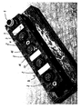
- FIG. 1 is a juxtaposition of sockets. 2 shown, via a common bus terminal 1 with a machine control are connected.
- Each plug connection 2 consists from five contacts 3 to 7, which are used for connection to sensors, Actuators or the like. Elements are provided.
- z. B. the Contacts 5 to 7 are used for power supply and control can be contacts 3 and 4 as diagnostic contacts be used, over which the proper function of the connected active or passive element can.
- the light exit surfaces are located 11 and 12 at an angle 9 of more than 90 ° to the insertion direction. 8 inclined, wherein the inclined light exit surface 12, 13 the Plug-in element, in the embodiment of the socket 2, facing away lies.
- the light exit surface 12, 13 in plan view, an annular, trapezoidal shape, wherein the Light exit surface - cf. Figures 3 and 6 - curved executed is.
- the light exit surface 12, 13 extends in the circumferential direction the socket 2 over a circumferential angle 14 of about 30 ° to 45 °, in particular about 35 °.
- the light exit surfaces form 12, 13 in a special embodiment of the invention Part of a light guide 15, which is the plug-in element, in the embodiment the socket, framed.
- the light guide 15 is advantageous a formed from a spherical zone 16 circular ring 17, so that the light exit surface 12, 13 through the surface segment a circular body, in the embodiment of a spherical surface 18 (Fig. 6) is formed.
- the light guide ring 15 is made of a light-conducting transparent Material manufactured, wherein the Lichtleitring 15 preferably in one piece is trained.
- the intended light exit surfaces 12 and 13 are roughly textured on the outer surface, in particular matted, what z. B. by a erosion greater than 39 is possible.
- the dividing lines 20 expediently have a part-circular cross-section and extend from the outer edge 21 of the light guide 15th up to a direction orthogonal to the plug-in direction 8, annular outer end surface 22, which is advantageously polished.
- Outside the light exit surfaces 12 and 13 is the outer, spherical surface of the light guide 15 finely structured, in particular satin, which is smaller by an erosion structure 27 is achievable.
- two are in the light guide ring 15
- Light exit surfaces 12, 13 are provided, preferably in one half of the light guide ring 15 are provided. From Designund Symmetry reasons, more joints 23 may be provided be.
- this is a light source Light element 25 at a distance from the light exit surface 12.
- the distance between the light exit surface 12 and the light element 25 is bridged by a light guide 26.
- the light guide body 26 has a light incident surface opposite to the light source 24, wherein the light entry surface 24 and the Light exit surface 12, 13 in an angle to each other Layers lie. That of the light entry surface 24 opposite End of the light guide 26 is from the light exit surface 12th or 13 formed, wherein the light guide 26 and the light guide 15 are expediently made in one piece.
- the outer surface 27th of the entire light guide except for the frosted and frosted Polished spherical surfaces.
- the light elements 25 are - such.
- B. Fig. 6 shows - preferably LEDs whose radiation at the light entry surface 24 of the Light guide 26 occurs. In the end of the light guide 26 this is extended like a hammer head, wherein the hammer head 29 on its free end face lying in the spherical surface 28 Light exit surface 12, 13 forms.
- the hammer head 29 is in one piece with the light guide ring 17 made of a transparent, light-conducting Material formed.
- a light guide 26 For mechanical mounting of the light guide ring on the housing of a Plug connection 2 are a light guide 26 approximately diametrically opposite insertion lugs 30 provided (Fig. 4).
- the light guide 26th formed such that it begins at the light entry surface 24 to the end hammer head 29 with the light exit surface 13 and 12, respectively, expanded substantially evenly. In this way, steps or the like are deliberately avoided and a wide spread of the at the light entry surface 24 incoming light reached.
- the display panel 10, 11 of Light exit surface 12, 13 is largely uniformly illuminated, ensuring a good visibility both from the plugging direction 8 as is given laterally.
- the plug-in projections 30 are corresponding to the hammer heads 29 executed so that a largely symmetrical structure achieved.
- the light guide ring 15 shown is in the embodiment 1 provided with M12 Gewindesteckan Wunschn; a expedient use is also with screwable plug connections other sizes possible. The diameters are useful of the light guide 15 is selected according to the plug connection.
Landscapes
- Illuminated Signs And Luminous Advertising (AREA)
- Details Of Connecting Devices For Male And Female Coupling (AREA)
- Monitoring And Testing Of Exchanges (AREA)
Description
- Fig. 1
- eine perspektivische Ansicht aus miteinander verketteten Steckbuchsen für Aktoren, Sensoren oder dgl. Elemente einer Maschinensteuerung,
- Fig. 2
- eine Draufsicht auf einen Lichtleitring,
- Fig. 3
- eine Seitenansicht eines Lichtleitrings,
- Fig. 4
- eine Ansicht eines Lichtleitrings von unten,
- Fig. 5
- in schematischer Darstellung die Oberflächenstruktur eines Lichtleitrings nach Fig. 2,
- Fig. 6
- eine weitere Seitenansicht des Lichtleitrings nach Fig. 2,
- Fig. 7
- eine perspektivische Ansicht des Lichtleitrings nach Fig. 2,
- Fig. 8
- einen Schnitt längs der Linie VIII-VIII in Fig. 4,
- Fig. 9
- eine perspektivische Ansicht eines Lichtleitrings in anderer Ausführungsform.
Claims (16)
- Zustandsanzeige für eine Steckverbindung, bestehend aus einem benachbart zum Steckelement (2) angeordneten Anzeigefeld (10, 11), das von einem Lichtelement (25) gespeist ist und eine Lichtaustrittsfläche (12, 13) aufweist, die in einem Winkel (9) von mehr als 90° zur Steckrichtung (8) geneigt ist und die geneigte Lichtaustrittsfläche (12, 13) dem Steckelement (2) abgewandt liegt,
dadurch gekennzeichnet, daß die Lichtaustrittsfläche (12, 13) Teil eines Lichtleitrings (15) aus einem lichtleitenden, transparenten Material ist, wobei der Lichtleitring (15) das Steckelement (2) umrahmt und die Lichtaustrittsfläche (12, 13) als Flächensegment in Steckrichtung gesehen eine gewölbt trapezförmige Gestalt hat. - Zustandsanzeige nach Anspruch 1,
dadurch gekennzeichnet, daß die Lichtaustrittsfläche (12, 13) als Flächensegment eines Kreiskörpers, insbesondere einer Kugeloberfläche (18) ausgebildet ist. - Zustandsanzeige nach Anspruch 1 oder 2,
dadurch gekennzeichnet, daß sich die Lichtaustrittsfläche (12, 13) über einen Umfangswinkel (14) von etwa 30° bis 45°, insbesondere etwa 35°, erstreckt. - Zustandsanzeige nach einem der Ansprüche 1 bis 3,
dadurch gekennzeichnet, daß der Lichtleitring (15) ein aus einer Kugelzone (16) gebildeter Kreisring (17) ist. - Zustandsanzeige nach Anspruch 4,
dadurch gekennzeichnet, daß der Lichtleitring (15) bis auf die Kugeloberfläche (28) des Kreisrings (17) und die Lichtaustrittsfläche (12, 13) poliert ist. - Zustandsanzeige nach einem der Ansprüche 1 bis 5,
dadurch gekennzeichnet, daß der Lichtleitring (15) einteilig gefertigt ist. - Zustandsanzeige nach einem der Ansprüche 1 bis 6,
dadurch gekennzeichnet, daß die Lichtaustrittsfläche (12, 13) grob strukturiert ist. - Zustandsanzeige nach einem der Ansprüche 1 bis 6,
dadurch gekennzeichnet, daß die Lichtaustrittsfläche (12, 13) mattiert ist., - Zustandsanzeige nach einem der Ansprüche 1 bis 8,
dadurch gekennzeichnet, daß die Lichtaustrittsfläche (12, 13) an ihren radialen Rändern (19) durch konstruktive Trennfugen (20) begrenzt sind. - Zustandsanzeige nach einem der Ansprüche 1 bis 9,
dadurch gekennzeichnet, daß die Oberfläche des Lichtleitrings (15) außerhalb der Lichtaustrittsflächen (12, 13) fein strukturiert, insbesondere satiniert ist. - Zustandsanzeige nach einem der Ansprüche 1 bis 10,
dadurch gekennzeichnet, daß der Lichtleitring (15) eine orthogonal zur Steckrichtung (8) liegende äußere Stirnfläche (22) aufweist, die insbesondere poliert ist. - Zustandsanzeige nach einem der Ansprüche 1 bis 11,
dadurch gekennzeichnet, daß der Lichtleitring (15) zwei Lichtaustrittsflächen (12, 13) aufweist, die vorzugsweise mit Abstand in einer Hälfte des Lichtleitrings (15) angeordnet sind. - Zustandsanzeige nach einem der Ansprüche 1 bis 12,
dadurch gekennzeichnet, daß das Lichtelement (25) mit Abstand zur Lichtaustrittsfläche (12, 13) liegt und der Abstand zwischen der Lichtaustrittsfläche (12, 13) und dem Lichtelement (25) von einem Lichtleitkörper (26) überbrückt ist. - Zustandsanzeige nach Anspruch 13,
dadurch gekennzeichnet, daß sich der Lichtleitkörper (26) von einer Lichteintrittsfläche (24) bis zur Lichtaustrittsfläche (12, 13) erweitert, vorzugsweise etwa gleichmäßig erweitert. - Zustandsanzeige nach Anspruch 13 oder 14,
dadurch gekennzeichnet, daß das Ende des Lichtleitkörpers (26) von der Lichtaustrittsfläche (12, 13) gebildet ist. - Zustandsanzeige nach einem der Ansprüche 13 bis 15,
dadurch gekennzeichnet, daß der Lichtleitkörper (26) und der Lichtleitring (15) einteilig ausgeführt sind.
Priority Applications (3)
| Application Number | Priority Date | Filing Date | Title |
|---|---|---|---|
| AT01127978T ATE286630T1 (de) | 2001-11-24 | 2001-11-24 | Zustandsanzeige für eine steckverbindung |
| EP01127978A EP1315248B1 (de) | 2001-11-24 | 2001-11-24 | Zustandsanzeige für eine Steckverbindung |
| DE50105038T DE50105038D1 (de) | 2001-11-24 | 2001-11-24 | Zustandsanzeige für eine Steckverbindung |
Applications Claiming Priority (1)
| Application Number | Priority Date | Filing Date | Title |
|---|---|---|---|
| EP01127978A EP1315248B1 (de) | 2001-11-24 | 2001-11-24 | Zustandsanzeige für eine Steckverbindung |
Publications (2)
| Publication Number | Publication Date |
|---|---|
| EP1315248A1 EP1315248A1 (de) | 2003-05-28 |
| EP1315248B1 true EP1315248B1 (de) | 2005-01-05 |
Family
ID=8179341
Family Applications (1)
| Application Number | Title | Priority Date | Filing Date |
|---|---|---|---|
| EP01127978A Expired - Lifetime EP1315248B1 (de) | 2001-11-24 | 2001-11-24 | Zustandsanzeige für eine Steckverbindung |
Country Status (3)
| Country | Link |
|---|---|
| EP (1) | EP1315248B1 (de) |
| AT (1) | ATE286630T1 (de) |
| DE (1) | DE50105038D1 (de) |
Cited By (1)
| Publication number | Priority date | Publication date | Assignee | Title |
|---|---|---|---|---|
| EP3864724B1 (de) * | 2018-10-11 | 2025-03-26 | HARTING Electric GmbH & Co. KG | Dichtungskörper für einen steckverbinder und steckverbinder |
Families Citing this family (2)
| Publication number | Priority date | Publication date | Assignee | Title |
|---|---|---|---|---|
| US6837725B1 (en) * | 2004-01-16 | 2005-01-04 | Deere & Company | Connector assembly |
| US9055687B2 (en) * | 2010-08-20 | 2015-06-09 | Rockwell Automation Technologies, Inc. | Input/output circuits and devices having physically corresponding status indicators |
Family Cites Families (6)
| Publication number | Priority date | Publication date | Assignee | Title |
|---|---|---|---|---|
| US4000405A (en) * | 1975-08-28 | 1976-12-28 | Product Concepts, Inc. | Electrical adaptor and night light |
| GB2268799B (en) * | 1992-07-13 | 1996-08-14 | Strix Ltd | Controls for electrical heating appliances |
| US5345520A (en) * | 1993-07-28 | 1994-09-06 | Grile Mark E | Electrical connector with an optical fiber connection detector |
| US5741152A (en) * | 1995-04-25 | 1998-04-21 | Amphenol Corporation | Electrical connector with indicator lights |
| DE19525843C1 (de) * | 1995-07-15 | 1996-07-11 | Telefunken Microelectron | Steckdose mit Beleuchtung |
| DE29619496U1 (de) * | 1996-11-09 | 1998-03-12 | ESCHA Bauelemente GmbH, 58553 Halver | Steckverbinder mit Leuchtanzeige |
-
2001
- 2001-11-24 EP EP01127978A patent/EP1315248B1/de not_active Expired - Lifetime
- 2001-11-24 AT AT01127978T patent/ATE286630T1/de active
- 2001-11-24 DE DE50105038T patent/DE50105038D1/de not_active Expired - Lifetime
Cited By (1)
| Publication number | Priority date | Publication date | Assignee | Title |
|---|---|---|---|---|
| EP3864724B1 (de) * | 2018-10-11 | 2025-03-26 | HARTING Electric GmbH & Co. KG | Dichtungskörper für einen steckverbinder und steckverbinder |
Also Published As
| Publication number | Publication date |
|---|---|
| EP1315248A1 (de) | 2003-05-28 |
| ATE286630T1 (de) | 2005-01-15 |
| DE50105038D1 (de) | 2005-02-10 |
Similar Documents
| Publication | Publication Date | Title |
|---|---|---|
| DE2132825C2 (de) | Elektrische Steckverbindung | |
| DE2263144A1 (de) | Zweiteilige elektrische verbindergehaeuseanordnung | |
| WO2015131212A1 (de) | Lichtleitelement für eine leuchteinheit | |
| DE102015105867A1 (de) | Rotationswinkelsensor mit Sockel und Rotationsmaschine | |
| DE102016123002A1 (de) | Vorrichtung zum ausleuchten eines vorgegebenen flächenbereiches | |
| EP3163258B1 (de) | Sensoreinheit | |
| EP1317021A1 (de) | Anschlussstück, Fluidleitung und fluidtechnische Einrichtung | |
| CH623680A5 (en) | Switching apparatus | |
| EP2991170A1 (de) | Anordnung mit Modulteilen und einstellbaren Kodiermitteln | |
| DE112015005333T5 (de) | Verfahren zur Montage eines Flüssigkeitssensors und Flüssigkeitssensor | |
| EP1315248A1 (de) | Zustandsanzeige für eine Steckverbindung | |
| EP1563579A1 (de) | Gehäuse zur aufnahme eines elektrischen gerätes | |
| DE10254919C5 (de) | Verteilerregulatorvorrichtung | |
| DE102005019945A1 (de) | Trägerwerkzeug für eine Schneidplatte mit zwei Schneiden und Schneidplatte mit zwei Schneiden | |
| EP0135053A1 (de) | Signalleuchte | |
| AT404299B (de) | Anschlussgarnitur | |
| DE8424990U1 (de) | Näherungsschalter | |
| EP3385608A1 (de) | Beleuchtungsvorrichtung für fahrzeuge | |
| DE19955257C1 (de) | Ventil, insbesondere Thermostatventil für Heizungsanlagen | |
| DE102020104322B4 (de) | Blendenanordnung für ein elektrisches Bauteil | |
| DE10300650B3 (de) | Verbindungselement für einen Handlauf | |
| DE102015101783A1 (de) | Passiv-Infrarot-Bewegungsmelder | |
| DE4138973A1 (de) | Kodierbarer steckverbinder | |
| DE202005019134U1 (de) | Trägerwerkzeug für eine Schneidplatte mit zwei Schneiden und Schneidplatte mit zwei Schneiden | |
| EP3550672B1 (de) | Verbindungselement |
Legal Events
| Date | Code | Title | Description |
|---|---|---|---|
| PUAI | Public reference made under article 153(3) epc to a published international application that has entered the european phase |
Free format text: ORIGINAL CODE: 0009012 |
|
| AK | Designated contracting states |
Designated state(s): AT BE CH CY DE DK ES FI FR GB GR IE IT LI LU MC NL PT SE TR |
|
| AX | Request for extension of the european patent |
Extension state: AL LT LV MK RO SI |
|
| 17P | Request for examination filed |
Effective date: 20030816 |
|
| 17Q | First examination report despatched |
Effective date: 20030918 |
|
| AKX | Designation fees paid |
Designated state(s): AT BE CH CY DE DK ES FI FR GB GR IE IT LI LU MC NL PT SE TR |
|
| GRAP | Despatch of communication of intention to grant a patent |
Free format text: ORIGINAL CODE: EPIDOSNIGR1 |
|
| GRAS | Grant fee paid |
Free format text: ORIGINAL CODE: EPIDOSNIGR3 |
|
| GRAA | (expected) grant |
Free format text: ORIGINAL CODE: 0009210 |
|
| AK | Designated contracting states |
Kind code of ref document: B1 Designated state(s): AT BE CH CY DE DK ES FI FR GB GR IE IT LI LU MC NL PT SE TR |
|
| PG25 | Lapsed in a contracting state [announced via postgrant information from national office to epo] |
Ref country code: IT Free format text: LAPSE BECAUSE OF FAILURE TO SUBMIT A TRANSLATION OF THE DESCRIPTION OR TO PAY THE FEE WITHIN THE PRESCRIBED TIME-LIMIT;WARNING: LAPSES OF ITALIAN PATENTS WITH EFFECTIVE DATE BEFORE 2007 MAY HAVE OCCURRED AT ANY TIME BEFORE 2007. THE CORRECT EFFECTIVE DATE MAY BE DIFFERENT FROM THE ONE RECORDED. Effective date: 20050105 Ref country code: GB Free format text: LAPSE BECAUSE OF FAILURE TO SUBMIT A TRANSLATION OF THE DESCRIPTION OR TO PAY THE FEE WITHIN THE PRESCRIBED TIME-LIMIT Effective date: 20050105 Ref country code: IE Free format text: LAPSE BECAUSE OF FAILURE TO SUBMIT A TRANSLATION OF THE DESCRIPTION OR TO PAY THE FEE WITHIN THE PRESCRIBED TIME-LIMIT Effective date: 20050105 Ref country code: FI Free format text: LAPSE BECAUSE OF FAILURE TO SUBMIT A TRANSLATION OF THE DESCRIPTION OR TO PAY THE FEE WITHIN THE PRESCRIBED TIME-LIMIT Effective date: 20050105 Ref country code: FR Free format text: LAPSE BECAUSE OF NON-PAYMENT OF DUE FEES Effective date: 20050105 Ref country code: TR Free format text: LAPSE BECAUSE OF FAILURE TO SUBMIT A TRANSLATION OF THE DESCRIPTION OR TO PAY THE FEE WITHIN THE PRESCRIBED TIME-LIMIT Effective date: 20050105 Ref country code: NL Free format text: LAPSE BECAUSE OF FAILURE TO SUBMIT A TRANSLATION OF THE DESCRIPTION OR TO PAY THE FEE WITHIN THE PRESCRIBED TIME-LIMIT Effective date: 20050105 |
|
| REG | Reference to a national code |
Ref country code: GB Ref legal event code: FG4D Free format text: NOT ENGLISH |
|
| REG | Reference to a national code |
Ref country code: CH Ref legal event code: EP Ref country code: CH Ref legal event code: NV Representative=s name: ISLER & PEDRAZZINI AG |
|
| REG | Reference to a national code |
Ref country code: IE Ref legal event code: FG4D Free format text: GERMAN |
|
| REF | Corresponds to: |
Ref document number: 50105038 Country of ref document: DE Date of ref document: 20050210 Kind code of ref document: P |
|
| PG25 | Lapsed in a contracting state [announced via postgrant information from national office to epo] |
Ref country code: DK Free format text: LAPSE BECAUSE OF FAILURE TO SUBMIT A TRANSLATION OF THE DESCRIPTION OR TO PAY THE FEE WITHIN THE PRESCRIBED TIME-LIMIT Effective date: 20050405 Ref country code: GR Free format text: LAPSE BECAUSE OF FAILURE TO SUBMIT A TRANSLATION OF THE DESCRIPTION OR TO PAY THE FEE WITHIN THE PRESCRIBED TIME-LIMIT Effective date: 20050405 Ref country code: SE Free format text: LAPSE BECAUSE OF FAILURE TO SUBMIT A TRANSLATION OF THE DESCRIPTION OR TO PAY THE FEE WITHIN THE PRESCRIBED TIME-LIMIT Effective date: 20050405 |
|
| PG25 | Lapsed in a contracting state [announced via postgrant information from national office to epo] |
Ref country code: ES Free format text: LAPSE BECAUSE OF FAILURE TO SUBMIT A TRANSLATION OF THE DESCRIPTION OR TO PAY THE FEE WITHIN THE PRESCRIBED TIME-LIMIT Effective date: 20050416 |
|
| NLV1 | Nl: lapsed or annulled due to failure to fulfill the requirements of art. 29p and 29m of the patents act | ||
| GBV | Gb: ep patent (uk) treated as always having been void in accordance with gb section 77(7)/1977 [no translation filed] |
Effective date: 20050105 |
|
| REG | Reference to a national code |
Ref country code: IE Ref legal event code: FD4D |
|
| PLBE | No opposition filed within time limit |
Free format text: ORIGINAL CODE: 0009261 |
|
| STAA | Information on the status of an ep patent application or granted ep patent |
Free format text: STATUS: NO OPPOSITION FILED WITHIN TIME LIMIT |
|
| PG25 | Lapsed in a contracting state [announced via postgrant information from national office to epo] |
Ref country code: CY Free format text: LAPSE BECAUSE OF FAILURE TO SUBMIT A TRANSLATION OF THE DESCRIPTION OR TO PAY THE FEE WITHIN THE PRESCRIBED TIME-LIMIT Effective date: 20051124 |
|
| PG25 | Lapsed in a contracting state [announced via postgrant information from national office to epo] |
Ref country code: BE Free format text: LAPSE BECAUSE OF NON-PAYMENT OF DUE FEES Effective date: 20051130 Ref country code: MC Free format text: LAPSE BECAUSE OF NON-PAYMENT OF DUE FEES Effective date: 20051130 Ref country code: LU Free format text: LAPSE BECAUSE OF NON-PAYMENT OF DUE FEES Effective date: 20051130 |
|
| 26N | No opposition filed |
Effective date: 20051006 |
|
| REG | Reference to a national code |
Ref country code: GB Ref legal event code: FG4D Free format text: NOT ENGLISH |
|
| EN | Fr: translation not filed | ||
| REG | Reference to a national code |
Ref country code: CH Ref legal event code: PCAR Free format text: ISLER & PEDRAZZINI AG;POSTFACH 1772;8027 ZUERICH (CH) |
|
| BERE | Be: lapsed |
Owner name: MURR-ELEKTRONIK G.M.B.H. Effective date: 20051130 |
|
| PG25 | Lapsed in a contracting state [announced via postgrant information from national office to epo] |
Ref country code: PT Free format text: LAPSE BECAUSE OF NON-PAYMENT OF DUE FEES Effective date: 20050605 |
|
| PGFP | Annual fee paid to national office [announced via postgrant information from national office to epo] |
Ref country code: CH Payment date: 20201118 Year of fee payment: 20 Ref country code: AT Payment date: 20201119 Year of fee payment: 20 Ref country code: DE Payment date: 20201119 Year of fee payment: 20 |
|
| REG | Reference to a national code |
Ref country code: DE Ref legal event code: R071 Ref document number: 50105038 Country of ref document: DE |
|
| REG | Reference to a national code |
Ref country code: AT Ref legal event code: MK07 Ref document number: 286630 Country of ref document: AT Kind code of ref document: T Effective date: 20211124 |