EP1314931A2 - Gas turbine fuel injector - Google Patents
Gas turbine fuel injector Download PDFInfo
- Publication number
- EP1314931A2 EP1314931A2 EP02027536A EP02027536A EP1314931A2 EP 1314931 A2 EP1314931 A2 EP 1314931A2 EP 02027536 A EP02027536 A EP 02027536A EP 02027536 A EP02027536 A EP 02027536A EP 1314931 A2 EP1314931 A2 EP 1314931A2
- Authority
- EP
- European Patent Office
- Prior art keywords
- fuel
- air
- injector
- tip
- combustor
- Prior art date
- Legal status (The legal status is an assumption and is not a legal conclusion. Google has not performed a legal analysis and makes no representation as to the accuracy of the status listed.)
- Granted
Links
Images


Classifications
-
- F—MECHANICAL ENGINEERING; LIGHTING; HEATING; WEAPONS; BLASTING
- F23—COMBUSTION APPARATUS; COMBUSTION PROCESSES
- F23C—METHODS OR APPARATUS FOR COMBUSTION USING FLUID FUEL OR SOLID FUEL SUSPENDED IN A CARRIER GAS OR AIR
- F23C7/00—Combustion apparatus characterised by arrangements for air supply
- F23C7/02—Disposition of air supply not passing through burner
-
- F—MECHANICAL ENGINEERING; LIGHTING; HEATING; WEAPONS; BLASTING
- F23—COMBUSTION APPARATUS; COMBUSTION PROCESSES
- F23C—METHODS OR APPARATUS FOR COMBUSTION USING FLUID FUEL OR SOLID FUEL SUSPENDED IN A CARRIER GAS OR AIR
- F23C7/00—Combustion apparatus characterised by arrangements for air supply
- F23C7/002—Combustion apparatus characterised by arrangements for air supply the air being submitted to a rotary or spinning motion
-
- F—MECHANICAL ENGINEERING; LIGHTING; HEATING; WEAPONS; BLASTING
- F23—COMBUSTION APPARATUS; COMBUSTION PROCESSES
- F23D—BURNERS
- F23D11/00—Burners using a direct spraying action of liquid droplets or vaporised liquid into the combustion space
- F23D11/10—Burners using a direct spraying action of liquid droplets or vaporised liquid into the combustion space the spraying being induced by a gaseous medium, e.g. water vapour
- F23D11/106—Burners using a direct spraying action of liquid droplets or vaporised liquid into the combustion space the spraying being induced by a gaseous medium, e.g. water vapour medium and fuel meeting at the burner outlet
- F23D11/107—Burners using a direct spraying action of liquid droplets or vaporised liquid into the combustion space the spraying being induced by a gaseous medium, e.g. water vapour medium and fuel meeting at the burner outlet at least one of both being subjected to a swirling motion
-
- F—MECHANICAL ENGINEERING; LIGHTING; HEATING; WEAPONS; BLASTING
- F23—COMBUSTION APPARATUS; COMBUSTION PROCESSES
- F23D—BURNERS
- F23D23/00—Assemblies of two or more burners
-
- F—MECHANICAL ENGINEERING; LIGHTING; HEATING; WEAPONS; BLASTING
- F05—INDEXING SCHEMES RELATING TO ENGINES OR PUMPS IN VARIOUS SUBCLASSES OF CLASSES F01-F04
- F05B—INDEXING SCHEME RELATING TO WIND, SPRING, WEIGHT, INERTIA OR LIKE MOTORS, TO MACHINES OR ENGINES FOR LIQUIDS COVERED BY SUBCLASSES F03B, F03D AND F03G
- F05B2250/00—Geometry
- F05B2250/20—Geometry three-dimensional
- F05B2250/25—Geometry three-dimensional helical
-
- F—MECHANICAL ENGINEERING; LIGHTING; HEATING; WEAPONS; BLASTING
- F23—COMBUSTION APPARATUS; COMBUSTION PROCESSES
- F23D—BURNERS
- F23D2900/00—Special features of, or arrangements for burners using fluid fuels or solid fuels suspended in a carrier gas
- F23D2900/00014—Pilot burners specially adapted for ignition of main burners in furnaces or gas turbines
-
- F—MECHANICAL ENGINEERING; LIGHTING; HEATING; WEAPONS; BLASTING
- F23—COMBUSTION APPARATUS; COMBUSTION PROCESSES
- F23D—BURNERS
- F23D2900/00—Special features of, or arrangements for burners using fluid fuels or solid fuels suspended in a carrier gas
- F23D2900/11101—Pulverising gas flow impinging on fuel from pre-filming surface, e.g. lip atomizers
Definitions
- the present invention relates to gas turbine engines, and more particularly, to a fuel injector for such engines.
- the combustion chamber of certain gas turbine engines may be an annular tube with a plurality of fuel injectors or nozzles that are spaced apart circumferentially.
- Each fuel injector in such an arrangement must be efficient and provide a proper distribution of an atomized fuel and air mixture in the zone surrounding the particular injector. Preferably this mixture is distributed as a conical spray. It is also important that the fuel be atomized in order to promote efficient burning of the fuel in the combustion chamber.
- the control of the spray cone can be effected by providing a swirl to the mixture as it leaves the injector.
- the swirl can be provided by deflectors or directing air jets to provide a vortex.
- such devices are often spaced apart from the actual fuel nozzles forming part of the fuel injector.
- a construction in accordance with the present invention comprises a fuel injector for a combustor in a gas turbine engine, wherein the combustor includes a combustor wall defining a combustion chamber tube surrounded by pressurized air, the injector comprising an injection tip assembly adapted to protrude, in use, through the combustor wall into the chamber, the injector tip including a first air passage forming an annular array communicating the pressurized air from outside the wall into the combustion chamber, a second air passage made up of an annular array of individual air passages spaced radially from the first air passage for communicating pressurized air from outside the wall into the combustion chamber, a first fuel gallery extending through the fuel injector tip and defining an annular fuel nozzle between the first air passage and the second air passages whereby the second air passage is arranged to atomize the fuel emanating from the first fuel nozzle, and a set of third air passages arranged in annular array in the injector tip spaced radially outwardly from the second air passages where
- a fuel tip with a second fuel gallery communicating with an axial fuel nozzle concentric and central to the first air passage, wherein the second fuel gallery is effective to supply primary fuel for ignition purposes.
- each passage in the second and third rows is formed with an axial component and an inwardly directed component which is the result of an inwardly directed angle offset and parallel to a plane extending through the axis of the injector tip in order to provide a swirl to the mixture.
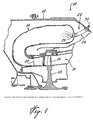
- FIG. 1 shows a combustor section 10 which includes an annular casing 12 and an annular combustor tube 14 concentric with a turbine section 16.
- the turbine section 16 is shown with a typical rotor 18 having blades 19 and a stator vane 20 upstream from the blades 19.
- a fuel injector 22, part of the present invention, is shown in Figs. 1 and 2 as being located at the end of the annular combustor tube 14 and directed axially thereof.
- the injector 22 is mounted to the casing 12 by means of a bracket 30.
- the injector includes a fitting 31 to be connected to a typical fuel line.
- the fuel injector 22 includes a stem portion which may be of the type described in U. S. Patent Application 08/960,331, filed October 29, 1997, entitled “Fuel Nozzle for Gas Turbine Engine", assigned to the applicant, and which is herein incorporated by reference.
- a shield 32 surrounds the stem 24.
- the fuel injector 22 also includes an injector tip 26 which is mounted to the combustor wall 28, as shown in Figs. 2 and 3. Only the front face of the tip 26 extends within the combustion chamber while most of the tip 26 is in the cooling air passage outside wall 28.
- the injector tip 26 includes a machined body 34.
- An axial recess in the body 34 defines the primary fuel chamber 36.
- An insert 50 provided within the recess defines the nozzle opening 44 communicating with the fuel chamber 36 for passing the primary fuel.
- a valving device 38 includes a spiral vane which causes the primary fuel to swirl within the chamber 36.
- the stem 46 of this valving device acts as a metering valve for the primary fuel as it exits through the nozzle 44.
- the primary fuel is used mainly for ignition purposes.
- a heat shield 42 surrounds the tip of the insert 50, and in particular, surrounds the nozzle opening 44.
- the heat shield 42 fits onto the insert 50.
- a second annular insert 51 is mounted to the body 34 concentrically of the insert 50 and forms part of the secondary fuel distribution gallery and nozzle.
- the secondary fuel passes through somewhat spiral passages making up the fuel gallery 48. The purpose of circulating the secondary fuel in this fashion is to keep the fuel spinning in the passages, thus eliminating stagnant zones in the fuel gallery in order to prevent coking and also to help cool the injector.
- the secondary fuel is eventually delivered to an annular fuel nozzle 54 which is also a swirler to provide the swirl to the secondary fuel.
- the secondary fuel sustains the combustion in the combustor after the fuel has been ignited.
- the fuel nozzle 54 is formed by the insert 51 and a cylindrical tubular head 55 which fits onto the tip body 34 and is concentric with the inserts 50 and 51.
- the head 55 includes openings which define the core air passage which in turn communicates with core air swirler passages 58 in the insert 51.
- These core air passages 58 can communicate with core air channel 60 to pass pressurized air coming from the cooling air between the casing and the combustor wall, to enter into the combustor. Theoretically, the core air coming out of channel 60 is concentric and inward of the annular film of secondary fuel exiting from the nozzle 54.
- a second row of annular air passages 62 is also provided in the head 55 and communicates with the pressurized cooling air immediately outside of the combustor wall 28.
- the individual passages 62 are generally designed to provide a swirl to the mix of air and fuel, and, in fact, the purpose of the pressurized air coming through the passages 62 is to atomize the secondary fuel film exiting from the nozzle 54.
- the passages 62 each have an axis x.
- the passages 62 have a swirl angle which is defined by axis x lying in a plane parallel to and offset a distance D from a plane through the center line CL of the tip 26, angled inwardly in that offset parallel plane to the center line CL. The offset is represented by the distance D in Fig.
- the tip head 55 is provided with a third annular row of air passages referred to as auxiliary air passages 64.
- the air passages are straight bores through enlarged ring 66 of the head 55.
- Each passage 64 has an axis y.
- the passages 64 may be defined in the same manner as the passages 62, that is, by axis y lying in a plane parallel to and offset a distance D 1 from a plane through the center line CL of the tip 26, angled inwardly in that offset plane to the center line CL.
- the offset is represented by the distance D 1 in Fig. 4a, and the angle of inclination of axis y to the center line CL is shown as ⁇ in Fig. 3.
- the passages 64 also communicate with the cooling air, such air being pressurized relative to the atmosphere within the combustor.
- the main purpose of the pressurized air passing through the passages 64 is to shape the cone of the fuel mixture being ejected from the face of the tip 26.
- the passages 64 can be provided such as to reduce the divergent angle of the cone and this can be customized to the combustor design.
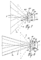
- the schematic illustration in Fig. 6 attempts to illustrate this phenomenon.
- the cone is represented by axes x and represents the cone of atomized spray of fuel and air, given the angle ⁇ of the passages 62, shown in Figs. 3 and 4a.
- the air passages 64 provide pressurized air forming a cone at a much smaller angle represented by the axes y in Fig. 6, to shape the atomized fuel cone, as shown at x 1 . Accordingly, the passages 64 will allow pressurized air to enter into the combustor in a spiral conical form influencing the spray distribution of the atomized fuel and pressurized air passing through nozzles or air passages 62.
- auxiliary air from passage 64 increases the availability of air in the fuel air mixture, thereby raising the air fuel ratio.
- Fig. 7 is an embodiment based on the tip 126, shown in Fig. 4b. As shown in Fig. 4b, the tip 126 includes passages 162 formed in the head 155 which are different in angle from those shown in Fig. 4a.
- the spray cone is represented in Fig. 7.
- the air passages 164, as shown in Figs. 4b and 7, are angled to provide a more closed shaped cone x 1 by means of the air following axes y and shaping the cone formed by axes x to ultimately form the cone x 1 .
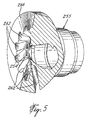
- Figs. 4c and 5 define a further embodiment of a fuel injector tip 226.
- Fig. 5 merely shows the head 255 and not the complete tip.
- air passages which would normally be separated as shown in Figs. 4a and 4b, are herein merged to form more extensive slots 262, 264 piercing the ring 266 and extending to the fuel nozzle 254.
- ⁇ ⁇ ⁇ ⁇ .
- the slots 262, 264 provide a much greater input of air compared to prior art tips.
- the passages 62, 64, 162, 164, and slots 262, 264 may be of different cross-sectional shapes and not necessarily formed as circular cylindrical bores. Naturally, the passages may be formed by presently known techniques. Such techniques include milling and brazing, electro discharge or laser.
Abstract
Description
- The present invention relates to gas turbine engines, and more particularly, to a fuel injector for such engines.
- The combustion chamber of certain gas turbine engines may be an annular tube with a plurality of fuel injectors or nozzles that are spaced apart circumferentially. Each fuel injector in such an arrangement must be efficient and provide a proper distribution of an atomized fuel and air mixture in the zone surrounding the particular injector. Preferably this mixture is distributed as a conical spray. It is also important that the fuel be atomized in order to promote efficient burning of the fuel in the combustion chamber. The control of the spray cone can be effected by providing a swirl to the mixture as it leaves the injector. The swirl can be provided by deflectors or directing air jets to provide a vortex. However, such devices are often spaced apart from the actual fuel nozzles forming part of the fuel injector.
- U. S. Patent 5,579,645, issued December 3, 1996 to the applicant, describes a fuel nozzle having first and second annular air passages and an annular fuel passage between the first and second air passages. The result is a conical air-fuel-air sandwich which greatly enhances the formation of atomized fuel droplets in order to improve the efficient burning of the fuel. It has been found that in some cases the spray cone formed by the nozzle is too wide and results in wall impingement. Therefore, there is a need to control the angle and pattern of the spray cone.
- It is, therefore, an aim of the present invention to provide an improved fuel injector that answers some of the needs that have been identified but is not presently being addressed by existing fuel injector technology.
- It is also advantageous to provide a higher air-to-fuel ratio; yet given the constraints with present fuel injector designs, it is difficult to increase this ratio.
- It is a further aim of the present invention to design a fuel injector for a gas turbine that has a compact arrangement of nozzles and passages for supplying both air and fuel to form a diverging spray of a mixture of atomized fuel and air with an increased air-to-fuel ratio.
- It is a further aim of the present invention to provide a more controlled spray shape.
- A construction in accordance with the present invention comprises a fuel injector for a combustor in a gas turbine engine, wherein the combustor includes a combustor wall defining a combustion chamber tube surrounded by pressurized air, the injector comprising an injection tip assembly adapted to protrude, in use, through the combustor wall into the chamber, the injector tip including a first air passage forming an annular array communicating the pressurized air from outside the wall into the combustion chamber, a second air passage made up of an annular array of individual air passages spaced radially from the first air passage for communicating pressurized air from outside the wall into the combustion chamber, a first fuel gallery extending through the fuel injector tip and defining an annular fuel nozzle between the first air passage and the second air passages whereby the second air passage is arranged to atomize the fuel emanating from the first fuel nozzle, and a set of third air passages arranged in annular array in the injector tip spaced radially outwardly from the second air passages whereby air from the third passages is arranged to shape the spray of the mixture of atomized fuel and air and to add supplemental air to the mixture.
- In a more specific embodiment of the present invention, there is provided a fuel tip with a second fuel gallery communicating with an axial fuel nozzle concentric and central to the first air passage, wherein the second fuel gallery is effective to supply primary fuel for ignition purposes.
- In a still more specific embodiment of the present invention, each passage in the second and third rows is formed with an axial component and an inwardly directed component which is the result of an inwardly directed angle offset and parallel to a plane extending through the axis of the injector tip in order to provide a swirl to the mixture.
- Having thus generally described the nature of the invention, reference will now be made to the accompanying drawings, showing by way of illustration, a preferred embodiment thereof, and in which:
- Fig. 1 is a simplified axial cross-section of the combustor of a gas turbine engine which includes the present invention;
- Fig. 2 is an enlarged perspective view of an embodiment of the present invention;
- Fig. 3 is a fragmentary, enlarged, cross-sectional, axial view of the embodiment shown in Fig. 2;
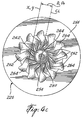
- Fig. 4a is a front elevation of the fuel injector shown in Figs. 2 and 3;
- Fig. 4b is a front elevation of the fuel injector in accordance with the present invention but showing a different embodiment thereof;
- Fig. 4c is a front elevation, similar to Figs. 4a and 4b, but showing yet another embodiment thereof;
- Fig. 5 is a fragmentary perspective view of the embodiment shown in Fig. 4c;
- Fig. 6 is a schematic view showing the flow of air and atomized fuel and the containment provided by an embodiment of the present invention; and
- Fig. 7 is a schematic view, similar to Fig. 6, and showing the effect of a different arrangement of the present invention.
-
- Referring now to the drawings, Fig. 1 shows a combustor section 10 which includes an
annular casing 12 and anannular combustor tube 14 concentric with aturbine section 16. Theturbine section 16 is shown with atypical rotor 18 havingblades 19 and astator vane 20 upstream from theblades 19. - A
fuel injector 22, part of the present invention, is shown in Figs. 1 and 2 as being located at the end of theannular combustor tube 14 and directed axially thereof. Theinjector 22 is mounted to thecasing 12 by means of abracket 30. The injector includes afitting 31 to be connected to a typical fuel line. There may beseveral fuel injectors 22 located on thewall 28 of the combustion chamber, and they may be circumferentially spaced apart. For the purpose of the present description, only onefuel injector 22 will be described. Thefuel injector 22 includes a stem portion which may be of the type described in U. S. Patent Application 08/960,331, filed October 29, 1997, entitled "Fuel Nozzle for Gas Turbine Engine", assigned to the applicant, and which is herein incorporated by reference. Ashield 32 surrounds thestem 24. - The
fuel injector 22 also includes aninjector tip 26 which is mounted to thecombustor wall 28, as shown in Figs. 2 and 3. Only the front face of thetip 26 extends within the combustion chamber while most of thetip 26 is in the cooling air passage outsidewall 28. - The
injector tip 26 includes amachined body 34. An axial recess in thebody 34 defines theprimary fuel chamber 36. An insert 50 provided within the recess defines the nozzle opening 44 communicating with thefuel chamber 36 for passing the primary fuel. Avalving device 38 includes a spiral vane which causes the primary fuel to swirl within thechamber 36. Thestem 46 of this valving device acts as a metering valve for the primary fuel as it exits through thenozzle 44. The primary fuel is used mainly for ignition purposes. - A
heat shield 42 surrounds the tip of the insert 50, and in particular, surrounds the nozzle opening 44. Theheat shield 42 fits onto the insert 50. - A second
annular insert 51 is mounted to thebody 34 concentrically of the insert 50 and forms part of the secondary fuel distribution gallery and nozzle. The secondary fuel passes through somewhat spiral passages making up thefuel gallery 48. The purpose of circulating the secondary fuel in this fashion is to keep the fuel spinning in the passages, thus eliminating stagnant zones in the fuel gallery in order to prevent coking and also to help cool the injector. The secondary fuel is eventually delivered to anannular fuel nozzle 54 which is also a swirler to provide the swirl to the secondary fuel. The secondary fuel sustains the combustion in the combustor after the fuel has been ignited. - The
fuel nozzle 54 is formed by theinsert 51 and a cylindricaltubular head 55 which fits onto thetip body 34 and is concentric with theinserts 50 and 51. Thehead 55 includes openings which define the core air passage which in turn communicates with core air swirler passages 58 in theinsert 51. These core air passages 58 can communicate withcore air channel 60 to pass pressurized air coming from the cooling air between the casing and the combustor wall, to enter into the combustor. Theoretically, the core air coming out ofchannel 60 is concentric and inward of the annular film of secondary fuel exiting from thenozzle 54. - A second row of
annular air passages 62 is also provided in thehead 55 and communicates with the pressurized cooling air immediately outside of thecombustor wall 28. Theindividual passages 62 are generally designed to provide a swirl to the mix of air and fuel, and, in fact, the purpose of the pressurized air coming through thepassages 62 is to atomize the secondary fuel film exiting from thenozzle 54. Thepassages 62 each have an axis x. Thepassages 62 have a swirl angle which is defined by axis x lying in a plane parallel to and offset a distance D from a plane through the center line CL of thetip 26, angled inwardly in that offset parallel plane to the center line CL. The offset is represented by the distance D in Fig. 4a, and the angle of inclination of axis x to center line CL is shown as in Fig. 3, where the plane of cross-section of Fig. 3 is parallel to the plane in which axis x lies being offset D from the plane through the center line CL. - As shown in Figs. 2 to 4a, the
tip head 55 is provided with a third annular row of air passages referred to asauxiliary air passages 64. As seen in these drawings, the air passages are straight bores throughenlarged ring 66 of thehead 55. Eachpassage 64 has an axis y. Thepassages 64 may be defined in the same manner as thepassages 62, that is, by axis y lying in a plane parallel to and offset a distance D1 from a plane through the center line CL of thetip 26, angled inwardly in that offset plane to the center line CL. The offset is represented by the distance D1 in Fig. 4a, and the angle of inclination of axis y to the center line CL is shown as in Fig. 3. Thepassages 64 also communicate with the cooling air, such air being pressurized relative to the atmosphere within the combustor. - The main purpose of the pressurized air passing through the
passages 64 is to shape the cone of the fuel mixture being ejected from the face of thetip 26. Thepassages 64 can be provided such as to reduce the divergent angle of the cone and this can be customized to the combustor design. The schematic illustration in Fig. 6 attempts to illustrate this phenomenon. The cone is represented by axes x and represents the cone of atomized spray of fuel and air, given the angle of thepassages 62, shown in Figs. 3 and 4a. However, theair passages 64 provide pressurized air forming a cone at a much smaller angle represented by the axes y in Fig. 6, to shape the atomized fuel cone, as shown at x1. Accordingly, thepassages 64 will allow pressurized air to enter into the combustor in a spiral conical form influencing the spray distribution of the atomized fuel and pressurized air passing through nozzles orair passages 62. - It is also noted that the addition of the auxiliary air from
passage 64 increases the availability of air in the fuel air mixture, thereby raising the air fuel ratio. - Within the formula provided hereinabove, the angle of the
passage 62 and angle ofpassage 64 can be varied to provide different shapes. Fig. 7 is an embodiment based on thetip 126, shown in Fig. 4b. As shown in Fig. 4b, thetip 126 includespassages 162 formed in the head 155 which are different in angle from those shown in Fig. 4a. The spray cone is represented in Fig. 7. Theair passages 164, as shown in Figs. 4b and 7, are angled to provide a more closed shaped cone x1 by means of the air following axes y and shaping the cone formed by axes x to ultimately form the cone x1. - Figs. 4c and 5 define a further embodiment of a
fuel injector tip 226. Fig. 5 merely shows thehead 255 and not the complete tip. In any event, air passages, which would normally be separated as shown in Figs. 4a and 4b, are herein merged to form moreextensive slots ring 266 and extending to thefuel nozzle 254. Thus, according to the above formula, thepassages 264 have the same offset, that is, the distance D = D1 and the offset planes coincide. Furthermore, ∠ = ∠ . Theslots - The
passages slots
Claims (4)
- In a fuel injector (22) for a combustor (10) in a gas turbine engine, wherein the combustor (10) includes a combustor wall (28) defining a combustion chamber tube (14) surrounded by pressurized air, the injector (22) characterised in that:an injector tip assembly (26) is adapted to protrude along a tip axis through the combustor wall (28) into the chamber, the injector tip (26) including at least an air passage (62) made up of an annular array of individual air passages (62) spaced radially from the tip axis and communicating the pressurized air from outside the combustor wall (28) into the combustor (10), a fuel gallery (48) extending through the fuel injector tip (26) and defining an annular fuel nozzle (54) radially inwardly from the air passage (62), whereby each air passage (62) in the annular array is formed to provide a swirl to the mixture and the air passage (62) is arranged to atomize the fuel emanating from the annular fuel nozzle (54), as a result of the passages (62) in the annular array each being in a plane offset from the plane through the tip axis of the injector tip (26), a distance D and the angle of the inwardly directed component of the axis of the passage is and further a second set of air passages (64) is arranged in an annular array in the injector tip (26) spaced radially outwardly from said air passages (62) with the distance of a plane, passing through each passage in the second set of air passages (64), from the plane passing through the tip axis is D1 and the angle of the inwardly directed component of each passage (64) of the second set to the tip axis is ϕ, whereby air from the second set of air passages (64) is arranged to shape the mixture of atomized fuel and air and to add supplemental air to the mixture.
- The fuel injector (22) as defined in claim 1, wherein D1 =D and angle =angle ϕ such that corresponding passages in the annular arrays (262, 264) merge to form slots through the injector tip for the purpose of atomizing, shaping, and providing additional air through the tip.
- A fuel injector (22) for a combustor (10) in a gas turbine engine, the injector (22) having an injector tip assembly (26), the injector tip assembly (26) having a tip axis and characterised in that:a machined body (34) having a central axis recess defining a fuel chamber (36), an insert member (50) including an axial nozzle (44) for passing fuel to the combustor (10) and a valve (38) for metering the fuel through the axial nozzle (44), the valve (38) comprising a spiral vane disposed within the fuel chamber to provide a spiral fuel flow path through a portion of the fuel chamber to the nozzle (44).
- A fuel injector (22) for a combustor in a gas turbine engine as defined in claim 3, wherein the injector tip (26) protrudes within the combustor (10) and the spiral vane is coaxial with the tip axis passing through the axial nozzle (44), the valve (38) further including a stem (46) which extends into the axial nozzle (44) along the tip axis to block the axial nozzle (44) when primary fuel is not required.
Applications Claiming Priority (3)
| Application Number | Priority Date | Filing Date | Title |
|---|---|---|---|
| US09/083,199 US6082113A (en) | 1998-05-22 | 1998-05-22 | Gas turbine fuel injector |
| US83199 | 1998-05-22 | ||
| EP99920473A EP1080327B1 (en) | 1998-05-22 | 1999-05-07 | Gas turbine fuel injector |
Related Parent Applications (2)
| Application Number | Title | Priority Date | Filing Date |
|---|---|---|---|
| EP99920473A Division EP1080327B1 (en) | 1998-05-22 | 1999-05-07 | Gas turbine fuel injector |
| EP99920473.8 Division | 1999-05-07 |
Publications (3)
| Publication Number | Publication Date |
|---|---|
| EP1314931A2 true EP1314931A2 (en) | 2003-05-28 |
| EP1314931A3 EP1314931A3 (en) | 2003-08-27 |
| EP1314931B1 EP1314931B1 (en) | 2012-03-14 |
Family
ID=22176816
Family Applications (2)
| Application Number | Title | Priority Date | Filing Date |
|---|---|---|---|
| EP02027536A Expired - Lifetime EP1314931B1 (en) | 1998-05-22 | 1999-05-07 | Gas turbine fuel injector |
| EP99920473A Expired - Lifetime EP1080327B1 (en) | 1998-05-22 | 1999-05-07 | Gas turbine fuel injector |
Family Applications After (1)
| Application Number | Title | Priority Date | Filing Date |
|---|---|---|---|
| EP99920473A Expired - Lifetime EP1080327B1 (en) | 1998-05-22 | 1999-05-07 | Gas turbine fuel injector |
Country Status (9)
| Country | Link |
|---|---|
| US (3) | US6082113A (en) |
| EP (2) | EP1314931B1 (en) |
| JP (1) | JP2002516976A (en) |
| CA (1) | CA2332359C (en) |
| CZ (1) | CZ20004341A3 (en) |
| DE (1) | DE69911008T2 (en) |
| PL (1) | PL191791B1 (en) |
| RU (1) | RU2000132717A (en) |
| WO (1) | WO1999061838A1 (en) |
Cited By (2)
| Publication number | Priority date | Publication date | Assignee | Title |
|---|---|---|---|---|
| EP2014988A1 (en) * | 2007-07-12 | 2009-01-14 | Snecma | Optimisation of an anti-coke film in an injection system |
| CN109140504A (en) * | 2017-06-19 | 2019-01-04 | 通用电气公司 | The aerodynamics of turbine fuel injector fastens |
Families Citing this family (162)
| Publication number | Priority date | Publication date | Assignee | Title |
|---|---|---|---|---|
| US6082113A (en) * | 1998-05-22 | 2000-07-04 | Pratt & Whitney Canada Corp. | Gas turbine fuel injector |
| DE10049517B4 (en) * | 2000-10-06 | 2005-05-12 | Robert Bosch Gmbh | Fuel injector |
| US6622488B2 (en) * | 2001-03-21 | 2003-09-23 | Parker-Hannifin Corporation | Pure airblast nozzle |
| US6546733B2 (en) | 2001-06-28 | 2003-04-15 | General Electric Company | Methods and systems for cooling gas turbine engine combustors |
| US6698208B2 (en) | 2001-12-14 | 2004-03-02 | Elliott Energy Systems, Inc. | Atomizer for a combustor |
| US6718770B2 (en) * | 2002-06-04 | 2004-04-13 | General Electric Company | Fuel injector laminated fuel strip |
| ITMI20021526A1 (en) * | 2002-07-11 | 2004-01-12 | Danieli Off Mecc | INJECTOR FOR METAL MATERIAL MELTING OVENS |
| US6823677B2 (en) * | 2002-09-03 | 2004-11-30 | Pratt & Whitney Canada Corp. | Stress relief feature for aerated gas turbine fuel injector |
| US6863228B2 (en) * | 2002-09-30 | 2005-03-08 | Delavan Inc. | Discrete jet atomizer |
| US7007864B2 (en) * | 2002-11-08 | 2006-03-07 | United Technologies Corporation | Fuel nozzle design |
| US6921034B2 (en) | 2002-12-12 | 2005-07-26 | General Electric Company | Fuel nozzle assembly |
| US6871488B2 (en) * | 2002-12-17 | 2005-03-29 | Pratt & Whitney Canada Corp. | Natural gas fuel nozzle for gas turbine engine |
| GB0230070D0 (en) * | 2002-12-23 | 2003-01-29 | Bowman Power Systems Ltd | A combustion device |
| JP4279562B2 (en) * | 2003-01-17 | 2009-06-17 | 富士フイルム株式会社 | Control method for solid-state imaging device |
| US7174717B2 (en) * | 2003-12-24 | 2007-02-13 | Pratt & Whitney Canada Corp. | Helical channel fuel distributor and method |
| US7104464B2 (en) | 2003-12-25 | 2006-09-12 | Kawasaki Jukogyo Kabushiki Kaisha | Fuel supply method and fuel supply system |
| US7043922B2 (en) * | 2004-01-20 | 2006-05-16 | Delavan Inc | Method of forming a fuel feed passage in the feed arm of a fuel injector |
| US7654088B2 (en) * | 2004-02-27 | 2010-02-02 | Pratt & Whitney Canada Corp. | Dual conduit fuel manifold for gas turbine engine |
| US7117678B2 (en) * | 2004-04-02 | 2006-10-10 | Pratt & Whitney Canada Corp. | Fuel injector head |
| DE102004027702A1 (en) * | 2004-06-07 | 2006-01-05 | Alstom Technology Ltd | Injector for liquid fuel and stepped premix burner with this injector |
| US8348180B2 (en) | 2004-06-09 | 2013-01-08 | Delavan Inc | Conical swirler for fuel injectors and combustor domes and methods of manufacturing the same |
| US7325402B2 (en) * | 2004-08-04 | 2008-02-05 | Siemens Power Generation, Inc. | Pilot nozzle heat shield having connected tangs |
| EP1705424B1 (en) * | 2005-03-04 | 2015-07-29 | Riello S.p.A. | Liquid-fuel burner combustion head |
| US7237730B2 (en) * | 2005-03-17 | 2007-07-03 | Pratt & Whitney Canada Corp. | Modular fuel nozzle and method of making |
| US7530231B2 (en) | 2005-04-01 | 2009-05-12 | Pratt & Whitney Canada Corp. | Fuel conveying member with heat pipe |
| US7559202B2 (en) * | 2005-11-15 | 2009-07-14 | Pratt & Whitney Canada Corp. | Reduced thermal stress fuel nozzle assembly |
| US8074901B2 (en) * | 2005-12-01 | 2011-12-13 | Uniwave, Inc. | Lubricator nozzle and emitter element |
| US7721436B2 (en) * | 2005-12-20 | 2010-05-25 | Pratt & Whitney Canada Corp. | Method of manufacturing a metal injection moulded combustor swirler |
| FR2896031B1 (en) * | 2006-01-09 | 2008-04-18 | Snecma Sa | MULTIMODE INJECTION DEVICE FOR COMBUSTION CHAMBER, IN PARTICULAR A TURBOREACTOR |
| US20070264602A1 (en) * | 2006-01-26 | 2007-11-15 | Frenette Henry E | Vapor fuel combustion system |
| JP5023526B2 (en) * | 2006-03-23 | 2012-09-12 | 株式会社Ihi | Combustor burner and combustion method |
| CN101206029B (en) * | 2006-12-21 | 2010-12-08 | 中国科学院工程热物理研究所 | Nozzle for minisize gas-turbine combustor |
| EP1985924A1 (en) * | 2007-04-23 | 2008-10-29 | Siemens Aktiengesellschaft | Swirler |
| US8146365B2 (en) * | 2007-06-14 | 2012-04-03 | Pratt & Whitney Canada Corp. | Fuel nozzle providing shaped fuel spray |
| US9079203B2 (en) | 2007-06-15 | 2015-07-14 | Cheng Power Systems, Inc. | Method and apparatus for balancing flow through fuel nozzles |
| US8316541B2 (en) | 2007-06-29 | 2012-11-27 | Pratt & Whitney Canada Corp. | Combustor heat shield with integrated louver and method of manufacturing the same |
| US7543383B2 (en) | 2007-07-24 | 2009-06-09 | Pratt & Whitney Canada Corp. | Method for manufacturing of fuel nozzle floating collar |
| US8276836B2 (en) * | 2007-07-27 | 2012-10-02 | General Electric Company | Fuel nozzle assemblies and methods |
| FR2919672B1 (en) * | 2007-07-30 | 2014-02-14 | Snecma | FUEL INJECTOR IN A TURBOMACHINE COMBUSTION CHAMBER |
| US7712313B2 (en) * | 2007-08-22 | 2010-05-11 | Pratt & Whitney Canada Corp. | Fuel nozzle for a gas turbine engine |
| DE102007043626A1 (en) | 2007-09-13 | 2009-03-19 | Rolls-Royce Deutschland Ltd & Co Kg | Gas turbine lean burn burner with fuel nozzle with controlled fuel inhomogeneity |
| US7658339B2 (en) * | 2007-12-20 | 2010-02-09 | Pratt & Whitney Canada Corp. | Modular fuel nozzle air swirler |
| WO2009121008A2 (en) | 2008-03-28 | 2009-10-01 | Exxonmobil Upstream Research Company | Low emission power generation and hydrocarbon recovery systems and methods |
| CA2934541C (en) | 2008-03-28 | 2018-11-06 | Exxonmobil Upstream Research Company | Low emission power generation and hydrocarbon recovery systems and methods |
| US8015816B2 (en) * | 2008-06-16 | 2011-09-13 | Delavan Inc | Apparatus for discouraging fuel from entering the heat shield air cavity of a fuel injector |
| JP4872992B2 (en) * | 2008-09-12 | 2012-02-08 | 株式会社日立製作所 | Combustor, fuel supply method for combustor, and modification method for combustor |
| US8261554B2 (en) * | 2008-09-17 | 2012-09-11 | General Electric Company | Fuel nozzle tip assembly |
| US8272218B2 (en) * | 2008-09-24 | 2012-09-25 | Siemens Energy, Inc. | Spiral cooled fuel nozzle |
| EP2344738B1 (en) | 2008-10-14 | 2019-04-03 | Exxonmobil Upstream Research Company | Method and system for controlling the products of combustion |
| US20100170253A1 (en) * | 2009-01-07 | 2010-07-08 | General Electric Company | Method and apparatus for fuel injection in a turbine engine |
| US8347631B2 (en) * | 2009-03-03 | 2013-01-08 | General Electric Company | Fuel nozzle liquid cartridge including a fuel insert |
| ATE540265T1 (en) * | 2009-04-06 | 2012-01-15 | Siemens Ag | SWIRL DEVICE, COMBUSTION CHAMBER AND GAS TURBINE WITH IMPROVED SWIRL |
| US8607570B2 (en) * | 2009-05-06 | 2013-12-17 | General Electric Company | Airblown syngas fuel nozzle with diluent openings |
| US20100281872A1 (en) * | 2009-05-06 | 2010-11-11 | Mark Allan Hadley | Airblown Syngas Fuel Nozzle With Diluent Openings |
| US8387393B2 (en) * | 2009-06-23 | 2013-03-05 | Siemens Energy, Inc. | Flashback resistant fuel injection system |
| US20110072823A1 (en) * | 2009-09-30 | 2011-03-31 | Daih-Yeou Chen | Gas turbine engine fuel injector |
| US8375548B2 (en) * | 2009-10-07 | 2013-02-19 | Pratt & Whitney Canada Corp. | Fuel nozzle and method of repair |
| EA023673B1 (en) | 2009-11-12 | 2016-06-30 | Эксонмобил Апстрим Рисерч Компани | Low emission power generation and hydrocarbon recovery system and method |
| MX341981B (en) | 2010-07-02 | 2016-09-08 | Exxonmobil Upstream Res Company * | Stoichiometric combustion with exhaust gas recirculation and direct contact cooler. |
| CA2801488C (en) | 2010-07-02 | 2018-11-06 | Exxonmobil Upstream Research Company | Low emission triple-cycle power generation systems and methods |
| JP5913305B2 (en) | 2010-07-02 | 2016-04-27 | エクソンモービル アップストリーム リサーチ カンパニー | Low emission power generation system and method |
| JP5906555B2 (en) | 2010-07-02 | 2016-04-20 | エクソンモービル アップストリーム リサーチ カンパニー | Stoichiometric combustion of rich air by exhaust gas recirculation system |
| US9033259B2 (en) * | 2010-12-23 | 2015-05-19 | General Electric Company | Method and system for mixing reactor feed |
| US10317081B2 (en) | 2011-01-26 | 2019-06-11 | United Technologies Corporation | Fuel injector assembly |
| RU2560099C2 (en) * | 2011-01-31 | 2015-08-20 | Дженерал Электрик Компани | Fuel nozzle (versions) |
| US8351780B2 (en) | 2011-02-01 | 2013-01-08 | Hamilton Sundstrand Corporation | Imaging system for hollow cone spray |
| TWI563165B (en) | 2011-03-22 | 2016-12-21 | Exxonmobil Upstream Res Co | Power generation system and method for generating power |
| TWI564474B (en) | 2011-03-22 | 2017-01-01 | 艾克頌美孚上游研究公司 | Integrated systems for controlling stoichiometric combustion in turbine systems and methods of generating power using the same |
| TWI593872B (en) | 2011-03-22 | 2017-08-01 | 艾克頌美孚上游研究公司 | Integrated system and methods of generating power |
| TWI563166B (en) | 2011-03-22 | 2016-12-21 | Exxonmobil Upstream Res Co | Integrated generation systems and methods for generating power |
| WO2012156631A1 (en) * | 2011-05-17 | 2012-11-22 | Snecma | Annular combustion chamber for a turbomachine |
| US9188063B2 (en) | 2011-11-03 | 2015-11-17 | Delavan Inc. | Injectors for multipoint injection |
| CN103134079B (en) * | 2011-11-30 | 2014-12-17 | 贵州航空发动机研究所 | Double-oil-circuit fuel nozzle |
| CN104428490B (en) | 2011-12-20 | 2018-06-05 | 埃克森美孚上游研究公司 | The coal bed methane production of raising |
| US9228744B2 (en) | 2012-01-10 | 2016-01-05 | General Electric Company | System for gasification fuel injection |
| US20130189632A1 (en) * | 2012-01-23 | 2013-07-25 | General Electric Company | Fuel nozzel |
| US9353682B2 (en) | 2012-04-12 | 2016-05-31 | General Electric Company | Methods, systems and apparatus relating to combustion turbine power plants with exhaust gas recirculation |
| US10273880B2 (en) | 2012-04-26 | 2019-04-30 | General Electric Company | System and method of recirculating exhaust gas for use in a plurality of flow paths in a gas turbine engine |
| US9784185B2 (en) | 2012-04-26 | 2017-10-10 | General Electric Company | System and method for cooling a gas turbine with an exhaust gas provided by the gas turbine |
| US9400104B2 (en) * | 2012-09-28 | 2016-07-26 | United Technologies Corporation | Flow modifier for combustor fuel nozzle tip |
| US9803865B2 (en) | 2012-12-28 | 2017-10-31 | General Electric Company | System and method for a turbine combustor |
| US9708977B2 (en) | 2012-12-28 | 2017-07-18 | General Electric Company | System and method for reheat in gas turbine with exhaust gas recirculation |
| US10100741B2 (en) | 2012-11-02 | 2018-10-16 | General Electric Company | System and method for diffusion combustion with oxidant-diluent mixing in a stoichiometric exhaust gas recirculation gas turbine system |
| US9869279B2 (en) | 2012-11-02 | 2018-01-16 | General Electric Company | System and method for a multi-wall turbine combustor |
| US9574496B2 (en) | 2012-12-28 | 2017-02-21 | General Electric Company | System and method for a turbine combustor |
| US9599070B2 (en) | 2012-11-02 | 2017-03-21 | General Electric Company | System and method for oxidant compression in a stoichiometric exhaust gas recirculation gas turbine system |
| US9631815B2 (en) | 2012-12-28 | 2017-04-25 | General Electric Company | System and method for a turbine combustor |
| US10107495B2 (en) | 2012-11-02 | 2018-10-23 | General Electric Company | Gas turbine combustor control system for stoichiometric combustion in the presence of a diluent |
| US9611756B2 (en) | 2012-11-02 | 2017-04-04 | General Electric Company | System and method for protecting components in a gas turbine engine with exhaust gas recirculation |
| US10215412B2 (en) | 2012-11-02 | 2019-02-26 | General Electric Company | System and method for load control with diffusion combustion in a stoichiometric exhaust gas recirculation gas turbine system |
| US10208677B2 (en) | 2012-12-31 | 2019-02-19 | General Electric Company | Gas turbine load control system |
| GB2524914B (en) * | 2013-01-02 | 2017-08-23 | Parker Hannifin Corp | Direct injection multipoint nozzle |
| US9581081B2 (en) | 2013-01-13 | 2017-02-28 | General Electric Company | System and method for protecting components in a gas turbine engine with exhaust gas recirculation |
| US9512759B2 (en) | 2013-02-06 | 2016-12-06 | General Electric Company | System and method for catalyst heat utilization for gas turbine with exhaust gas recirculation |
| US9562692B2 (en) | 2013-02-06 | 2017-02-07 | Siemens Aktiengesellschaft | Nozzle with multi-tube fuel passageway for gas turbine engines |
| US9938861B2 (en) | 2013-02-21 | 2018-04-10 | Exxonmobil Upstream Research Company | Fuel combusting method |
| TW201502356A (en) | 2013-02-21 | 2015-01-16 | Exxonmobil Upstream Res Co | Reducing oxygen in a gas turbine exhaust |
| US10221762B2 (en) | 2013-02-28 | 2019-03-05 | General Electric Company | System and method for a turbine combustor |
| US9284933B2 (en) | 2013-03-01 | 2016-03-15 | Delavan Inc | Fuel nozzle with discrete jet inner air swirler |
| US9618261B2 (en) | 2013-03-08 | 2017-04-11 | Exxonmobil Upstream Research Company | Power generation and LNG production |
| TW201500635A (en) | 2013-03-08 | 2015-01-01 | Exxonmobil Upstream Res Co | Processing exhaust for use in enhanced oil recovery |
| US20140250945A1 (en) | 2013-03-08 | 2014-09-11 | Richard A. Huntington | Carbon Dioxide Recovery |
| CN105008499A (en) | 2013-03-08 | 2015-10-28 | 埃克森美孚上游研究公司 | Power generation and methane recovery from methane hydrates |
| TWI654368B (en) | 2013-06-28 | 2019-03-21 | 美商艾克頌美孚上游研究公司 | System, method and media for controlling exhaust gas flow in an exhaust gas recirculation gas turbine system |
| US9835089B2 (en) | 2013-06-28 | 2017-12-05 | General Electric Company | System and method for a fuel nozzle |
| US9617914B2 (en) | 2013-06-28 | 2017-04-11 | General Electric Company | Systems and methods for monitoring gas turbine systems having exhaust gas recirculation |
| US9631542B2 (en) | 2013-06-28 | 2017-04-25 | General Electric Company | System and method for exhausting combustion gases from gas turbine engines |
| US9587510B2 (en) | 2013-07-30 | 2017-03-07 | General Electric Company | System and method for a gas turbine engine sensor |
| US9903588B2 (en) | 2013-07-30 | 2018-02-27 | General Electric Company | System and method for barrier in passage of combustor of gas turbine engine with exhaust gas recirculation |
| US9951658B2 (en) | 2013-07-31 | 2018-04-24 | General Electric Company | System and method for an oxidant heating system |
| US9545604B2 (en) | 2013-11-15 | 2017-01-17 | General Electric Company | Solids combining system for a solid feedstock |
| US10030588B2 (en) | 2013-12-04 | 2018-07-24 | General Electric Company | Gas turbine combustor diagnostic system and method |
| US9752458B2 (en) | 2013-12-04 | 2017-09-05 | General Electric Company | System and method for a gas turbine engine |
| US10227920B2 (en) | 2014-01-15 | 2019-03-12 | General Electric Company | Gas turbine oxidant separation system |
| US9863267B2 (en) | 2014-01-21 | 2018-01-09 | General Electric Company | System and method of control for a gas turbine engine |
| US9915200B2 (en) | 2014-01-21 | 2018-03-13 | General Electric Company | System and method for controlling the combustion process in a gas turbine operating with exhaust gas recirculation |
| US10079564B2 (en) | 2014-01-27 | 2018-09-18 | General Electric Company | System and method for a stoichiometric exhaust gas recirculation gas turbine system |
| US9657938B2 (en) | 2014-02-07 | 2017-05-23 | Eugene R. Frenette | Fuel combustion system |
| JP6433162B2 (en) * | 2014-02-12 | 2018-12-05 | 株式会社エンプラス | Nozzle plate for fuel injector |
| US20150285502A1 (en) * | 2014-04-08 | 2015-10-08 | General Electric Company | Fuel nozzle shroud and method of manufacturing the shroud |
| EP2940389A1 (en) * | 2014-05-02 | 2015-11-04 | Siemens Aktiengesellschaft | Combustor burner arrangement |
| US10047633B2 (en) | 2014-05-16 | 2018-08-14 | General Electric Company | Bearing housing |
| US10655542B2 (en) | 2014-06-30 | 2020-05-19 | General Electric Company | Method and system for startup of gas turbine system drive trains with exhaust gas recirculation |
| US9885290B2 (en) | 2014-06-30 | 2018-02-06 | General Electric Company | Erosion suppression system and method in an exhaust gas recirculation gas turbine system |
| US10060359B2 (en) | 2014-06-30 | 2018-08-28 | General Electric Company | Method and system for combustion control for gas turbine system with exhaust gas recirculation |
| JP6347692B2 (en) * | 2014-07-30 | 2018-06-27 | 北海道オリンピア株式会社 | Burner device for cremation furnace or incinerator |
| US10184403B2 (en) | 2014-08-13 | 2019-01-22 | Pratt & Whitney Canada Corp. | Atomizing fuel nozzle |
| CN104165379A (en) * | 2014-09-01 | 2014-11-26 | 北京华清燃气轮机与煤气化联合循环工程技术有限公司 | Combustor head structure with cooling device |
| US9822980B2 (en) * | 2014-09-24 | 2017-11-21 | Pratt & Whitney Canada Corp. | Fuel nozzle |
| US9752774B2 (en) | 2014-10-03 | 2017-09-05 | Pratt & Whitney Canada Corp. | Fuel nozzle |
| US9765974B2 (en) | 2014-10-03 | 2017-09-19 | Pratt & Whitney Canada Corp. | Fuel nozzle |
| US10317083B2 (en) | 2014-10-03 | 2019-06-11 | Pratt & Whitney Canada Corp. | Fuel nozzle |
| US9819292B2 (en) | 2014-12-31 | 2017-11-14 | General Electric Company | Systems and methods to respond to grid overfrequency events for a stoichiometric exhaust recirculation gas turbine |
| US9869247B2 (en) | 2014-12-31 | 2018-01-16 | General Electric Company | Systems and methods of estimating a combustion equivalence ratio in a gas turbine with exhaust gas recirculation |
| US10788212B2 (en) | 2015-01-12 | 2020-09-29 | General Electric Company | System and method for an oxidant passageway in a gas turbine system with exhaust gas recirculation |
| US10094566B2 (en) | 2015-02-04 | 2018-10-09 | General Electric Company | Systems and methods for high volumetric oxidant flow in gas turbine engine with exhaust gas recirculation |
| US10253690B2 (en) | 2015-02-04 | 2019-04-09 | General Electric Company | Turbine system with exhaust gas recirculation, separation and extraction |
| US10316746B2 (en) | 2015-02-04 | 2019-06-11 | General Electric Company | Turbine system with exhaust gas recirculation, separation and extraction |
| US10731860B2 (en) * | 2015-02-05 | 2020-08-04 | Delavan, Inc. | Air shrouds with air wipes |
| US10267270B2 (en) | 2015-02-06 | 2019-04-23 | General Electric Company | Systems and methods for carbon black production with a gas turbine engine having exhaust gas recirculation |
| US10145269B2 (en) | 2015-03-04 | 2018-12-04 | General Electric Company | System and method for cooling discharge flow |
| US10480792B2 (en) | 2015-03-06 | 2019-11-19 | General Electric Company | Fuel staging in a gas turbine engine |
| US9932940B2 (en) | 2015-03-30 | 2018-04-03 | Honeywell International Inc. | Gas turbine engine fuel cooled cooling air heat exchanger |
| US9897321B2 (en) | 2015-03-31 | 2018-02-20 | Delavan Inc. | Fuel nozzles |
| US10385809B2 (en) | 2015-03-31 | 2019-08-20 | Delavan Inc. | Fuel nozzles |
| US9863638B2 (en) * | 2015-04-01 | 2018-01-09 | Delavan Inc. | Air shrouds with improved air wiping |
| WO2016160037A1 (en) | 2015-04-03 | 2016-10-06 | Frenette Eugene R | Fuel combustion system |
| GB2543803B (en) * | 2015-10-29 | 2019-10-30 | Rolls Royce Plc | A combustion chamber assembly |
| US11020758B2 (en) * | 2016-07-21 | 2021-06-01 | University Of Louisiana At Lafayette | Device and method for fuel injection using swirl burst injector |
| US10876477B2 (en) | 2016-09-16 | 2020-12-29 | Delavan Inc | Nozzles with internal manifolding |
| CN107289460B (en) * | 2017-06-10 | 2019-08-02 | 北京航空航天大学 | A kind of oil-poor direct-injection air atomizer spray nozzle of pre- membranous type |
| US11118698B2 (en) * | 2018-07-23 | 2021-09-14 | Pratt & Whiiney Canada Corp. | Damping mechanism for valves |
| US11118785B2 (en) * | 2018-10-26 | 2021-09-14 | Delavan Inc. | Fuel injectors for exhaust heaters |
| US10967394B2 (en) * | 2018-11-01 | 2021-04-06 | Rolls-Royce Corporation | Fluid atomizer |
| US10557630B1 (en) | 2019-01-15 | 2020-02-11 | Delavan Inc. | Stackable air swirlers |
| FR3105818B1 (en) * | 2019-12-31 | 2022-08-26 | Fives Pillard | Low NOx Burner |
| GB2592267A (en) * | 2020-02-24 | 2021-08-25 | Altair Uk Ltd | Pulse nozzle for filter cleaning systems |
| US11639687B2 (en) | 2020-10-22 | 2023-05-02 | Pratt & Whitney Canada Corp. | Fuel injectors and method of purging fuel injectors |
| CN114643431B (en) * | 2020-12-02 | 2023-11-03 | 中国航发商用航空发动机有限责任公司 | Combined welding method for aeroengine fuel nozzle assembly |
| KR20220088167A (en) * | 2020-12-18 | 2022-06-27 | 한화에어로스페이스 주식회사 | Fuel supply device |
| CN112984558A (en) * | 2021-03-17 | 2021-06-18 | 中国航发动力股份有限公司 | Natural gas nozzle of gas turbine |
| US11639795B2 (en) | 2021-05-14 | 2023-05-02 | Pratt & Whitney Canada Corp. | Tapered fuel gallery for a fuel nozzle |
Family Cites Families (40)
| Publication number | Priority date | Publication date | Assignee | Title |
|---|---|---|---|---|
| US3129891A (en) * | 1964-04-21 | Fuel nozzle | ||
| US1875457A (en) * | 1932-09-06 | Torkild valdemar hemmingsen | ||
| GB493434A (en) * | 1937-06-16 | 1938-10-07 | Bataafsche Petroleum | A fuel-cooled atomiser for internal combustion engines |
| US2690648A (en) * | 1951-07-03 | 1954-10-05 | Dowty Equipment Ltd | Means for conducting the flow of liquid fuel for feeding burners of gas turbine engines |
| US3067582A (en) * | 1955-08-11 | 1962-12-11 | Phillips Petroleum Co | Method and apparatus for burning fuel at shear interface between coaxial streams of fuel and air |
| GB831477A (en) * | 1957-04-15 | 1960-03-30 | John Frances Campbell | Liquid fuel injection nozzle |
| US2968925A (en) * | 1959-11-25 | 1961-01-24 | William E Blevans | Fuel nozzle head for anti-coking |
| FR1282186A (en) * | 1960-12-02 | 1962-01-19 | Siderurgie Fse Inst Rech | Hydrocarbon injector in blast furnaces |
| US3302399A (en) * | 1964-11-13 | 1967-02-07 | Westinghouse Electric Corp | Hollow conical fuel spray nozzle for pressurized combustion apparatus |
| US3483700A (en) * | 1967-09-27 | 1969-12-16 | Caterpillar Tractor Co | Dual fuel injection system for gas turbine engine |
| US3516252A (en) * | 1969-02-26 | 1970-06-23 | United Aircraft Corp | Fuel manifold system |
| US3684186A (en) * | 1970-06-26 | 1972-08-15 | Ex Cell O Corp | Aerating fuel nozzle |
| JPS4931059Y1 (en) * | 1970-11-30 | 1974-08-22 | ||
| US3912164A (en) * | 1971-01-11 | 1975-10-14 | Parker Hannifin Corp | Method of liquid fuel injection, and to air blast atomizers |
| FR2145340A5 (en) * | 1971-07-08 | 1973-02-16 | Hinderks M V | |
| JPS5342897B2 (en) * | 1972-11-09 | 1978-11-15 | ||
| US4028888A (en) * | 1974-05-03 | 1977-06-14 | Norwalk-Turbo Inc. | Fuel distribution manifold to an annular combustion chamber |
| US4170108A (en) * | 1975-04-25 | 1979-10-09 | Rolls-Royce Limited | Fuel injectors for gas turbine engines |
| US4216652A (en) * | 1978-06-08 | 1980-08-12 | General Motors Corporation | Integrated, replaceable combustor swirler and fuel injector |
| US4258544A (en) * | 1978-09-15 | 1981-03-31 | Caterpillar Tractor Co. | Dual fluid fuel nozzle |
| US4362022A (en) * | 1980-03-03 | 1982-12-07 | United Technologies Corporation | Anti-coke fuel nozzle |
| US4467610A (en) * | 1981-04-17 | 1984-08-28 | General Electric Company | Gas turbine fuel system |
| US4491272A (en) * | 1983-01-27 | 1985-01-01 | Ex-Cell-O Corporation | Pressure atomizing fuel injection assembly |
| DE3564024D1 (en) * | 1984-02-29 | 1988-09-01 | Lucas Ind Plc | Combustion equipment |
| EP0204553B1 (en) * | 1985-06-07 | 1989-06-07 | Ruston Gas Turbines Limited | Combustor for gas turbine engine |
| JPS63194111A (en) * | 1987-02-06 | 1988-08-11 | Hitachi Ltd | Combustion method for gas fuel and equipment thereof |
| US4773596A (en) * | 1987-04-06 | 1988-09-27 | United Technologies Corporation | Airblast fuel injector |
| US4854127A (en) * | 1988-01-14 | 1989-08-08 | General Electric Company | Bimodal swirler injector for a gas turbine combustor |
| AT400181B (en) * | 1990-10-15 | 1995-10-25 | Voest Alpine Ind Anlagen | BURNERS FOR THE COMBUSTION OF FINE-GRAIN TO DUST-SHAPED, SOLID FUELS |
| US5161379A (en) * | 1991-12-23 | 1992-11-10 | United Technologies Corporation | Combustor injector face plate cooling scheme |
| JP2839777B2 (en) * | 1991-12-24 | 1998-12-16 | 株式会社東芝 | Fuel injection nozzle for gas turbine combustor |
| US5222357A (en) * | 1992-01-21 | 1993-06-29 | Westinghouse Electric Corp. | Gas turbine dual fuel nozzle |
| US5288021A (en) * | 1992-08-03 | 1994-02-22 | Solar Turbines Incorporated | Injection nozzle tip cooling |
| US5256352A (en) * | 1992-09-02 | 1993-10-26 | United Technologies Corporation | Air-liquid mixer |
| US5423178A (en) * | 1992-09-28 | 1995-06-13 | Parker-Hannifin Corporation | Multiple passage cooling circuit method and device for gas turbine engine fuel nozzle |
| US5505045A (en) * | 1992-11-09 | 1996-04-09 | Fuel Systems Textron, Inc. | Fuel injector assembly with first and second fuel injectors and inner, outer, and intermediate air discharge chambers |
| EP0700498B1 (en) * | 1993-06-01 | 1998-10-21 | Pratt & Whitney Canada, Inc. | Radially mounted air blast fuel injector |
| FR2721694B1 (en) * | 1994-06-22 | 1996-07-19 | Snecma | Cooling of the take-off injector of a combustion chamber with two heads. |
| US6141968A (en) * | 1997-10-29 | 2000-11-07 | Pratt & Whitney Canada Corp. | Fuel nozzle for gas turbine engine with slotted fuel conduits and cover |
| US6082113A (en) * | 1998-05-22 | 2000-07-04 | Pratt & Whitney Canada Corp. | Gas turbine fuel injector |
-
1998
- 1998-05-22 US US09/083,199 patent/US6082113A/en not_active Expired - Lifetime
-
1999
- 1999-05-07 EP EP02027536A patent/EP1314931B1/en not_active Expired - Lifetime
- 1999-05-07 EP EP99920473A patent/EP1080327B1/en not_active Expired - Lifetime
- 1999-05-07 JP JP2000551194A patent/JP2002516976A/en active Pending
- 1999-05-07 RU RU2000132717/06A patent/RU2000132717A/en not_active Application Discontinuation
- 1999-05-07 CZ CZ20004341A patent/CZ20004341A3/en unknown
- 1999-05-07 DE DE69911008T patent/DE69911008T2/en not_active Expired - Fee Related
- 1999-05-07 WO PCT/CA1999/000412 patent/WO1999061838A1/en active IP Right Grant
- 1999-05-07 CA CA002332359A patent/CA2332359C/en not_active Expired - Lifetime
- 1999-05-07 PL PL344339A patent/PL191791B1/en not_active IP Right Cessation
-
2000
- 2000-05-25 US US09/577,577 patent/US6289677B1/en not_active Expired - Lifetime
- 2000-05-25 US US09/577,578 patent/US6247317B1/en not_active Expired - Lifetime
Non-Patent Citations (1)
| Title |
|---|
| None |
Cited By (4)
| Publication number | Priority date | Publication date | Assignee | Title |
|---|---|---|---|---|
| EP2014988A1 (en) * | 2007-07-12 | 2009-01-14 | Snecma | Optimisation of an anti-coke film in an injection system |
| FR2918716A1 (en) * | 2007-07-12 | 2009-01-16 | Snecma Sa | OPTIMIZATION OF ANTI-COKE FILM IN AN INJECTION SYSTEM |
| US8276388B2 (en) | 2007-07-12 | 2012-10-02 | Snecma | Optimizing an anti-coke film in an injector system for a gas turbine engine |
| CN109140504A (en) * | 2017-06-19 | 2019-01-04 | 通用电气公司 | The aerodynamics of turbine fuel injector fastens |
Also Published As
| Publication number | Publication date |
|---|---|
| CA2332359A1 (en) | 1999-12-02 |
| EP1080327A1 (en) | 2001-03-07 |
| EP1314931B1 (en) | 2012-03-14 |
| PL191791B1 (en) | 2006-07-31 |
| DE69911008D1 (en) | 2003-10-09 |
| CA2332359C (en) | 2008-10-07 |
| US6082113A (en) | 2000-07-04 |
| US6247317B1 (en) | 2001-06-19 |
| RU2000132717A (en) | 2002-12-10 |
| CZ20004341A3 (en) | 2002-01-16 |
| EP1080327B1 (en) | 2003-09-03 |
| PL344339A1 (en) | 2001-11-05 |
| US6289677B1 (en) | 2001-09-18 |
| JP2002516976A (en) | 2002-06-11 |
| DE69911008T2 (en) | 2004-04-01 |
| WO1999061838A1 (en) | 1999-12-02 |
| EP1314931A3 (en) | 2003-08-27 |
Similar Documents
| Publication | Publication Date | Title |
|---|---|---|
| EP1080327B1 (en) | Gas turbine fuel injector | |
| EP1323982B1 (en) | Fuel nozzle for a gas turbine engine | |
| CA1289756C (en) | Bimodal swirler injector for a gas turbine combustor | |
| EP2003398B1 (en) | Fuel nozzle providing shaped fuel spray | |
| US8033114B2 (en) | Multimode fuel injector for combustion chambers, in particular of a jet engine | |
| US8726668B2 (en) | Fuel atomization dual orifice fuel nozzle | |
| EP1605204B1 (en) | methods of manufacturing conical swirlers for fuel injectors | |
| EP0893650B1 (en) | Multi-swirler carburetor | |
| EP0722065B1 (en) | Fuel injector arrangement for gas-or liquid-fuelled turbine | |
| US8387391B2 (en) | Aerodynamically enhanced fuel nozzle | |
| US6622488B2 (en) | Pure airblast nozzle | |
| US7891193B2 (en) | Cooling of a multimode fuel injector for combustion chambers, in particular of a jet engine | |
| US7520745B2 (en) | Burner for a gas turbine | |
| US20050268614A1 (en) | Premixing burner with impingement cooled centerbody and method of cooling centerbody | |
| US20120151928A1 (en) | Cooling flowpath dirt deflector in fuel nozzle | |
| JPH07217451A (en) | Fuel injection device | |
| KR19980018381A (en) | Fuel nozzle assembly and liquid fuel injection method for gas turbine combustor | |
| CN108731029B (en) | Jet fuel nozzle | |
| US7086234B2 (en) | Gas turbine combustion chamber with defined fuel input for the improvement of the homogeneity of the fuel-air mixture | |
| JP2965639B2 (en) | Gas turbine combustor | |
| US11448175B1 (en) | Fuel nozzle |
Legal Events
| Date | Code | Title | Description |
|---|---|---|---|
| PUAI | Public reference made under article 153(3) epc to a published international application that has entered the european phase |
Free format text: ORIGINAL CODE: 0009012 |
|
| AC | Divisional application: reference to earlier application |
Ref document number: 1080327 Country of ref document: EP Kind code of ref document: P |
|
| AK | Designated contracting states |
Designated state(s): DE FR GB IT SE |
|
| PUAL | Search report despatched |
Free format text: ORIGINAL CODE: 0009013 |
|
| RIC1 | Information provided on ipc code assigned before grant |
Ipc: 7F 23D 11/38 B Ipc: 7F 23D 11/10 A |
|
| AK | Designated contracting states |
Designated state(s): DE FR GB IT SE |
|
| 17P | Request for examination filed |
Effective date: 20030818 |
|
| AKX | Designation fees paid |
Designated state(s): DE FR GB |
|
| 17Q | First examination report despatched |
Effective date: 20070525 |
|
| GRAP | Despatch of communication of intention to grant a patent |
Free format text: ORIGINAL CODE: EPIDOSNIGR1 |
|
| GRAS | Grant fee paid |
Free format text: ORIGINAL CODE: EPIDOSNIGR3 |
|
| GRAA | (expected) grant |
Free format text: ORIGINAL CODE: 0009210 |
|
| AC | Divisional application: reference to earlier application |
Ref document number: 1080327 Country of ref document: EP Kind code of ref document: P |
|
| AK | Designated contracting states |
Kind code of ref document: B1 Designated state(s): DE FR GB |
|
| REG | Reference to a national code |
Ref country code: GB Ref legal event code: FG4D |
|
| REG | Reference to a national code |
Ref country code: DE Ref legal event code: R096 Ref document number: 69944104 Country of ref document: DE Effective date: 20120510 |
|
| PLBE | No opposition filed within time limit |
Free format text: ORIGINAL CODE: 0009261 |
|
| STAA | Information on the status of an ep patent application or granted ep patent |
Free format text: STATUS: NO OPPOSITION FILED WITHIN TIME LIMIT |
|
| 26N | No opposition filed |
Effective date: 20121217 |
|
| REG | Reference to a national code |
Ref country code: DE Ref legal event code: R097 Ref document number: 69944104 Country of ref document: DE Effective date: 20121217 |
|
| PGFP | Annual fee paid to national office [announced via postgrant information from national office to epo] |
Ref country code: DE Payment date: 20140430 Year of fee payment: 16 |
|
| REG | Reference to a national code |
Ref country code: DE Ref legal event code: R119 Ref document number: 69944104 Country of ref document: DE |
|
| REG | Reference to a national code |
Ref country code: FR Ref legal event code: PLFP Year of fee payment: 18 |
|
| PG25 | Lapsed in a contracting state [announced via postgrant information from national office to epo] |
Ref country code: DE Free format text: LAPSE BECAUSE OF NON-PAYMENT OF DUE FEES Effective date: 20151201 |
|
| REG | Reference to a national code |
Ref country code: FR Ref legal event code: PLFP Year of fee payment: 19 |
|
| REG | Reference to a national code |
Ref country code: FR Ref legal event code: PLFP Year of fee payment: 20 |
|
| PGFP | Annual fee paid to national office [announced via postgrant information from national office to epo] |
Ref country code: FR Payment date: 20180423 Year of fee payment: 20 |
|
| PGFP | Annual fee paid to national office [announced via postgrant information from national office to epo] |
Ref country code: GB Payment date: 20180419 Year of fee payment: 20 |
|
| REG | Reference to a national code |
Ref country code: GB Ref legal event code: PE20 Expiry date: 20190506 |
|
| PG25 | Lapsed in a contracting state [announced via postgrant information from national office to epo] |
Ref country code: GB Free format text: LAPSE BECAUSE OF EXPIRATION OF PROTECTION Effective date: 20190506 |