EP1314677A2 - Managing method and system for building equipment and elevator - Google Patents
Managing method and system for building equipment and elevator Download PDFInfo
- Publication number
- EP1314677A2 EP1314677A2 EP02021769A EP02021769A EP1314677A2 EP 1314677 A2 EP1314677 A2 EP 1314677A2 EP 02021769 A EP02021769 A EP 02021769A EP 02021769 A EP02021769 A EP 02021769A EP 1314677 A2 EP1314677 A2 EP 1314677A2
- Authority
- EP
- European Patent Office
- Prior art keywords
- building equipment
- elevator
- building
- history database
- indicating
- Prior art date
- Legal status (The legal status is an assumption and is not a legal conclusion. Google has not performed a legal analysis and makes no representation as to the accuracy of the status listed.)
- Granted
Links
Images


Classifications
-
- B—PERFORMING OPERATIONS; TRANSPORTING
- B66—HOISTING; LIFTING; HAULING
- B66B—ELEVATORS; ESCALATORS OR MOVING WALKWAYS
- B66B5/00—Applications of checking, fault-correcting, or safety devices in elevators
-
- B—PERFORMING OPERATIONS; TRANSPORTING
- B66—HOISTING; LIFTING; HAULING
- B66B—ELEVATORS; ESCALATORS OR MOVING WALKWAYS
- B66B3/00—Applications of devices for indicating or signalling operating conditions of elevators
-
- B—PERFORMING OPERATIONS; TRANSPORTING
- B66—HOISTING; LIFTING; HAULING
- B66B—ELEVATORS; ESCALATORS OR MOVING WALKWAYS
- B66B3/00—Applications of devices for indicating or signalling operating conditions of elevators
- B66B3/002—Indicators
- B66B3/008—Displaying information not related to the elevator, e.g. weather, publicity, internet or TV
Definitions
- the present invention relates to a building equipment and elevator managing method and a building equipment and elevator managing system, and more particularly to a building equipment and elevator managing method and a building equipment and elevator managing system suitable for enabling each of the occupants of a building, especially the occupants of condominiums, to confirm histories of changes in the condition and the operating conditions of building equipment, by means of display devices installed in the public space (hereinafter referred to as the "public space") such as the elevator hall and the elevator cars in such a building.
- public space such as the elevator hall and the elevator cars in such a building.
- the elevator is one of the principal pieces of building equipment primarily serving for the transportation within a building and is subject to periodical inspection for maintaining its function. Further, the recent elevator is provided with an abnormality monitoring system so that the occurrence and the sign of abnormality are detected to be notified to a remote monitoring center.
- Japanese Patent Laid-Open No. 4-313581 discloses a monitoring system capable of recording and storing various histories including the past troubles, alarms or the like
- Japanese Patent Laid-Open No. 8-310760 discloses a system for enabling the history of repair works to be displayed on and printed by means of a portable terminal to be carried by each serviceman.
- Japanese Patent Laid-Open No. 2000-090374 discloses a method for indicating, for confirmation, the operating signal currently used in the elevator control circuit on the display device in the maintenance control center.
- Japanese Patent Laid-Open No. 11-272972 discloses a method for transmitting the signal telling the maintenance and inspection work is in progress when a card is kept inserted into a terminal of the remote monitoring system while transmitting the signal telling the completion of the maintenance and inspection work when the card is removed from the terminal.
- Building equipment and equipment relating to the building in general include various facilities such as elevators, power supply equipment, pumping and water service equipment, illumination equipment, air conditioning equipment, entrance/exit control equipment, a front door, disaster preventive equipment, a crime prevention camera, and a parking facility. These various facilities are individually provided with control systems, monitoring systems, and abnormality notification systems.
- a first object of the present invention is to provide a managing method and a managing system of building equipment designed for being capable of easily providing the occupants of the building with the information on the conditions, troubles, repairs and the like of the building equipment.
- 11-272972 is designed only for enabling the monitoring center to confirm the maintenance and inspection work in progress and the completion of the maintenance and inspection work and is not designed for providing the information on the inspection of the building equipment to the occupants of the building nor designed for evaluating the levels of the services provided by a plurality of servicing companies and a plurality of servicemen.
- a second object of the present invention is to provide a managing method and a managing system for the building equipment designed not only for being capable of evaluating the levels of the services provided by a plurality of servicing companies and a plurality of servicemen but also for being suitable for providing highly satisfactory services to the occupants of the building.
- the present invention in one aspect, comprises a equipment condition history database for recording the information on the past troubles and repairs of a building, the display devices installed in public spaces such as an elevator hall and/or in an elevator car where the existences of such display devices can readily be recognized for use by the individual occupants of the building, and an input device whereby a request for the indication of the information on the condition of the building equipment can be inputted for being displayed on each display device in response to the input of a request for such indication by each occupant of the building.
- the present invention in another aspect, comprises a control system installed for each building, display devices and input devices installed in an elevator hall and/or in an elevator car, a monitoring center connected with the control systems each installed in a plurality of buildings, a database for individual servicemen provided in the monitoring center, and a means for updating through the input device the database for individual servicemen by inputting the data of the individual services provided to the building concerned.
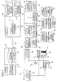
- Fig. 1 is a system configuration diagram of a managing system of building equipment and elevator according to an embodiment of the present invention.
- the managing system mainly comprises a control system 10, a display device 15, an input device 16, an elevator controller 20, controllers 30 for various pieces of building equipment, and a monitoring center 40.
- the control system 10 comprises a supervisory controller 11 for executing various processing, which will be described later, and a building equipment condition database 12 that records changes in the building equipment condition.
- the control system 10 is connected with various controllers through an equipment control network 13.
- the content of the information indicated on the display devices 15 which are installed in the public spaces such as an elevator hall and/or an elevator car where the display devices are readily recognized by the individual occupants of the building is controlled by a display device controller 14. Further, the input device 16 is installed near the display device 15. In the case of an example given in Fig. 1, a floor selecting button 22 in the elevator car 21 and a call button 23 in the elevator hall also serve as the input devices 16.
- the building equipment includes a power supply equipment 31, pumping and water service equipment 32, an illumination facility 33, an air conditioner 34, an entrance/exit controller 35, an entrance door 36, disaster preventive equipment 37, a crime prevention camera 38, a parking facility 39 and the like.
- a building equipment controller 30 is provided for each building equipment; however, the illumination facility 33 and the air conditioner 34 are controlled by the building equipment controller 30 common to each other, the entrance door 36 is connected with the entrance/exit control system 35 of other building equipment and the disaster preventive equipment 37 does not have a specific controller 30 of the building equipment.
- the monitoring center 40 is provided with a remote monitoring controller 41 for processing at the monitoring center, which will be described later, a database for individual building equipment 42 associated with the equipment condition database 12, and a database for individual servicemen 43, which are respectively connected with the control system 10 through a communication line 44.
- Fig. 2 is a diagram illustrating the outline of a managing system of the building equipment and the elevator according to an embodiment of the present invention.
- Fig. 2 shows the actions of various pieces of the building equipment, various systems, individual occupants of the building, and individual servicemen to be taken with the lapse of the time.
- an abnormality detection signal is outputted to the control system 10, and such abnormality will more or less influence the occupants of the building.
- the control system 10 Upon reception of the abnormality detection signal, the control system 10 not only notifies the monitoring center of the occurrence of the abnormality 40 but also makes the display device 15 indicate the occurrence of the abnormality so that the individual occupants of the building will either visually or aurally be notified of the occurrence of the abnormality.
- the monitoring center 40 upon reception of the signal telling the occurrence of the abnormality, analyzes the abnormality not only to demand the dispatch of the servicemen, if necessary, but also to transmit the actions to be taken, including the dispatch of the servicemen and the provision of the information on how to cope with the abnormality, to the control system 10.
- the control system 10 upon reception of the demand for the dispatch of the servicemen or the instruction for how to cope with the abnormality, makes the display device 15 indicate the progress of the measures taken against the abnormality and the progress of the repair work so that the individual occupants of the building will be able to know visually that the countermeasure against the abnormality is currently in progress.
- the servicemen are called out by the monitoring center 40, the servicemen are dispatched for repair work to the building concerned.
- the control system 10 updates the content of the equipment condition database 12 and makes the display device 15 indicate the completion of the repair work so that the individual occupants of the building will be able to visually confirm the completion of the repair work.
- the control system 10 transmits the data of the completed repair work to the monitoring center 40, and the monitoring center 40 not only evaluates the repair work but also updates the database for individual building equipment 42 and the database for individual servicemen 43 to process the data for the payments to be made to the individual servicemen and the service companies.
- each of the individual occupants of the building to confirm the content of the database 12 for changes in the conditions of the individual building equipment and machinery.
- the input device 16 by inputting the demand for that purpose to the input device 16, it is possible for any occupant of the building to refer to the content of the building equipment condition database 12 and to display it on the display device 15, thereby visually confirming changes in the conditions of the building equipment and machinery.
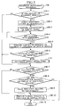
- Fig. 3 is a diagram illustrating a program for building equipment control processing 100.
- the building equipment control processing program 100 is executed by the supervisory controller 11 of the control system 10. Similarly to the case of the processing program described below, the start and stop of the program are made either periodically or by means of the interrupt request signal when necessary by operation of the operation system (not shown).
- step 100-1 When the abnormality of the equipment is detected in step 100-1, the signal notifying the occurrence of the abnormality is sent to the monitoring center 40 in step 100-2, and the occurrence of the abnormality is made to be indicated on the display device 15 in step 100-3.
- step 100-4 the response from the monitoring center 40 is awaited, and the content of the response or the progress of the processing is made to be indicated on the display device 15 in step 100-5 when the response is received. The content of response or the progress of the processing will be described later.
- step 100-6 the processing proceeds to the subroutine 110 for the processing during the repair work which will be described later.
- step 100-7 it is confirmed whether there is any indication relating to "abnormality" on the display device.
- the indication relating to "abnormality” means the indication that abnormal condition remains unremoved in steps 100-3 and 100-5 or the indication that the repair work has been completed in step 110-7 in the case where the repair work is completed by the processing 110 during the repair work as is described later.
- the indication relating to "abnormality" is made in step 100-7, the conditions for terminating the indication needs to be confirmed in step 100-8.
- the conditions for terminating the indication can be the expiration of indication period such as that 3 days have passed from the time when the indication of the completion of the repair work was made, or the confirmation of the completion of the repair work, through the input device 16, made by any one of the occupants who had noticed the indication of the completion of the repair work, or the input of the command requiring the termination of the display, which can be arbitrarily set depending on the condition of the building concerned.
- step 100-8 When the conditions for terminating the indication of abnormality are not satisfied in step 100-8, the equipment control processing 100 is terminated without executing the following steps in order to continue the indication of the abnormality.
- the indication relating to "abnormality” is terminated in step 100-9.
- the command for the indication of ordinary information is given to the display device 15 in step 100-10 to terminate the equipment control processing 100.
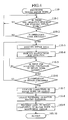
- Fig. 4 shows an example of a program for processing during the repair work 110.
- step 110-1 is for awaiting the input of the command for the start of repair work by a serviceman to the input device 16.
- the processing proceeds to the following steps.
- step 110-3 the information necessary for the trouble or repair of the building equipment is made to be indicated on the display device 15.
- step 110-4 the instructions relating to the repair work of the building equipment, if any, are made to be indicated on the display device 15.
- the step 110-3 and 110-4 provide the serviceman concerned with necessary assistances for their works from the control system 10 and the monitoring center 40.
- step 110-5 the input of the information for notifying the completion of the repair work by the serviceman concerned is awaited, and when the input for notifying the completion of the repair work is made, the control system 10 checks the conditions of the serviced building equipment or machinery to examine whether it is repaired satisfactorily in step 110-6. Until the result of the repair work is approved, the processing returns to the step 110-3 to repeat the previously mentioned processing. When the completion of the repair work is confirmed in step 110-6, the completion of the repair work is indicated on the display device 15 in step 110-7.
- step 110-8 the equipment conditions database 12 is updated, and in step 110-9, the data relating the completion of the repair work (the input by each serviceman and the data of the equipment condition confirmed by the control system 10) is transmitted to the monitoring center 40 to return to the stage 100 for the equipment control processing from the stage 110 for the processing during the repair work.
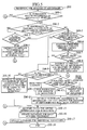
- Fig. 5 is a flowchart corresponding to a program for abnormality analysis processing 200 by the monitoring center.
- the abnormality analysis processing 200 by the monitoring center 40 is started.
- the signal notifying the abnormality of the equipment is received in step 200-1, whether the abnormality is of transient nature such as the instantaneous interruption of the power supply or not is confirmed in step 200-2.
- the abnormality is of transient nature in step 200-2, whether the present state is normal or not is confirmed in step 200-3.
- step 200-3 When it is confirmed that the present state is normal in step 200-3, there are no needs of repair work and inspection, so that the command for making the indication of "The transient abnormality has been removed and the normal state is recovered" is selected in step 200-4 to let the processing jump to stage B.
- step 200-5 When it is found that the present state is not normal in step 200-3, or when it is found that the abnormality is not transient one in step 200-2, whether the abnormality can be corrected through the remote control from the monitoring center 40 needs to be confirmed in step 200-5.
- the correction through the remote control system means to correct any temporary abnormal condition of the program by re-writing such data through the remote control system.
- the correcting operation through the remote control system is executed in step 200-6, and whether the normal state is recovered is confirmed in step 200-7.
- the indication, "The abnormality is removed, and normal state is recovered by remote control” is made in step 200-8 to let the processing jump to stage B.
- step 200-7 When the normal state cannot be recovered in step 200-7, or when the correction through the remote control system in step 200-5 is not possible, it is necessary to confirm whether the abnormality requires the dispatch of the servicemen for repairing or not in step 200-9.
- the command for the indication "A minor abnormality that can be corrected at the time of the next inspection"
- step 200-10 When it is found necessary to dispatch the servicemen in step 200-9, it is necessary to confirm whether the servicemen need to be dispatched from own company or from other company in step 200-11, and when the servicemen need to be dispatched from own company, the command for indicating the need of the dispatch of the servicemen of own company is inputted in step 200-12.
- step 200-11 When it is found that the servicemen of other company need to be dispatched in step 200-11, reference is made to the database for individual servicemen to select the company and the servicemen to which the servicing is to be entrusted, and the command for requesting the dispatch of the servicemen is inputted in step 200-13. Then, the command for the indication, "An abnormality has occurred and the request for dispatch of servicemen has been made" is selected in step 200-14.
- the data for the commanded indications is transmitted to the control system 10. Then, the database for individual building equipment 42 is updated in step 200-16, and the database for individual servicemen 43 is updated in step 200-17.
- Fig. 6 shows an example of a program for processing to be executed 210 by the monitoring center when the repair work is completed.
- the command for requesting the dispatch of the servicemen is inputted in the course of the previously mentioned abnormality analysis processing 200
- the data relating to the completion of the repair work from the control system 10 is awaited in step 210-1 of the processing stage 210.
- the database for individual building equipment 42 is updated in step 210-2.
- the repair work is evaluated in step 210-3.
- the repair work is evaluated in terms of the degree of difficulty of the abnormality, length of repair work time it takes from the command for dispatch of the servicemen to the completion of the work, the frequency of servicing required before completing the repair work or the like so that the amount of the payment for the servicing can be decided according to the rating of the quality of servicing.
- the database for individual servicemen 43 is updated according to the result of the evaluation.
- processing is executed for the payments to the contracted company and servicemen.
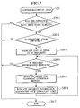
- Fig. 7 shows an example of a program for building equipment history processing 120.
- the occupants of the building can confirm the content of the building equipment condition database 12 which stores the data of the change in the building equipment and machinery condition in the past.
- the operation for confirming the building equipment conditions is made in step 120-1, and the building equipment historical data can be indicated on the display device 15 in step 120-2, provided that the identification code of the operator coincides with a regular code.
- the list of the historical data to be displayed can be displayed.
- the command for requesting the indication of the detailed information is inputted in step 120-4
- the building equipment condition database 12 is read out in step 120-5, and the detailed information is indicated in step 120-6 in response to the identification code of the operator.
- the processing comes to an end when there is no input of the command for the indication of the detailed information in step 120-4.
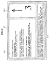
- Fig. 8 shows an example of the layout of display areas of a display device for the indication of the data.
- the display device 15 capable of displaying the characters and diagrams and commonly used for the display devices of the computers are used, but, (in the case of the present invention) the display device needs to include the information display area 15-1 for displaying the information of the building equipment out of the contents of the building equipment condition database 12.
- the display area of the display device is designed to include the elevator information area 15-2 which serve as the floor selector to indicate the position of the car.
- the floor selecting buttons 22 and the call buttons 23 are designed to serve as the input device 16 too, each user is required to follow some special instructions to operate these buttons because of the limited number of the buttons and thus it is convenient for the users to have an operating procedure explanation area 15-3.
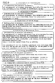
- Fig. 9 shows examples of the written information to be indicated on the display device. These indications respectively correspond to a series of processing to be executed from the time of the occurrence of any abnormality such as the processing to be executed (1) at the time of occurrence of abnormality, (2) at the time of the operation in progress and (3) at the time of the completion of repair work.
- Fig. 9 (4) Each occupant of the building who has operated the buttons for the history of the building equipment or machinery will have the histories such as one described in Fig. 9 (4) indicated on the display device.
- the indication as in Fig. 9 (5) is displayed; for the correction through the remote control system to be processed in step 200-8, the indication as in Fig. 9 (6) is displayed; for the minor abnormality to be processed in step 200-1, the indication as in Fig. 9 (7) is displayed.
- the building equipment and elevator managing system comprises the control system 10 installed in each building, the display device 15 installed in the elevator hall and/or in the car 21 of each elevator, and the monitoring center 40 connected with the control systems in a plurality of buildings.
- the building equipment and elevator managing system comprises the equipment condition database 12 provided in the control system 10 in order to record the change in the conditions of the individual pieces of the building equipment 20, 31 through 39, the database for individual building equipment 42, and the database for individual servicemen 43, respectively associated with the building equipment condition database 12 provided in the monitoring center 40, the input device 16 for inputting the command for requesting the content of the service to the building equipment and the indication on the display device 15, the display controller 14 for letting the content of the building equipment condition database 12 be indicated on the display device 15, and the record control means (installed in the remote monitoring controller 41) for updating the database for individual servicemen according to the data concerning the content of the service inputted through the input device 16.
- the present embodiment it is possible for any occupant of the building to readily have the information concerning the troubles and repairs of the building equipment indicated selectively on the display device. Further, the present embodiment makes it possible for each occupant of the building to have the information concerning the levels of the services provided from a plurality of contracted companies and their servicemen indicated on-demand-basis, thereby providing the occupants of the building with high-quality services. Furthermore, the present embodiment enables the occupants of the building to have the information concerning the abnormality such as the transient abnormality which did not require the dispatch of the servicemen reported or disclosed.
- the method comprises the steps: providing the monitoring center with a database for individual building equipment and a database for individual servicemen; notifying the monitoring center of the occurrence abnormality to, this step being executed by the control system; deciding on the dispatch of the servicemen, this step being executed by the monitoring center; transmitting the data concerning the completion of the repair work to the monitoring center in response to the input of the data concerning the completion of the repair work inputted from the input device, this step being executed by the control system; and updating the content of the database for individual servicemen, this step being executed by the monitoring center.
- the step in which the monitoring center decides on the dispatch of the servicemen includes the step of selecting the servicemen to be dispatched according to the content of the record in the database for individual servicemen.
- the method uses an input device installed in the vicinity of the display device, the control system executing: a step of detecting abnormality of building equipment; a step of notifying a monitoring center of the occurrence of the abnormality; a step of letting the display device indicate the occurrence of the abnormality; a step of receiving the response from the monitoring center; a step of letting the display device indicate the content of the response from the monitoring center; a step of updating the database according to the input from the input device; a step of letting the display device indicate the information concerning the completion of the repair work; and a step of transmitting the data concerning the completed repair work to the monitoring center.
- the method includes a step of receiving the signal telling the occurrence of abnormality from the monitoring center; a step of analyzing the nature of the abnormality; a step of requesting the dispatch of the servicemen; a step of transmitting the content of the response to the notification of the abnormality to the control system; a step of receiving data concerning the completion of the repair work from the control system; a step of evaluating the quality of service of each serviceman; a step of updating the database for individual servicemen; a step of updating the database for individual servicemen; and a step of processing concerning the payments to individual servicemen and the companies to which they belong.
- the present invention readily enables each occupant of a building to selectively and visually access the information concerning the trouble and repair of the building equipment by having such information indicated on the display device.
Landscapes
- Indicating And Signalling Devices For Elevators (AREA)
- Maintenance And Inspection Apparatuses For Elevators (AREA)
- Alarm Systems (AREA)
- Management, Administration, Business Operations System, And Electronic Commerce (AREA)
Abstract
Description
Claims (11)
- A building equipment managing method using a history database (12) for recording the conditions of building equipment, a display device (15) installed in public spaces of a building, and an input device (16) installed in the public spaces of the building for inputting a request for the indication of necessary information, the method comprising the steps of:recording a change in a condition of the building equipment in the history database (12), andin response to receiving a request for indicating a content which is recorded in the history database (12) from the input device (16), indicating on the display device (15) the content which is recorded in the history database (12).
- A building equipment and elevator managing method using a history database (12) for recording the conditions of building equipment, display devices (15) installed in an elevator hall and/or in an elevator car (21), and input devices (16) installed in the vicinity of the display devices (15) for inputting a request for the indication of necessary information to the display device (15), the method comprising the steps of:recording a change in a condition of the building equipment in the history database, andin response to receiving a request for indicating a content which is recorded in the history database (12) from the input device (16), indicating on the display device (15) the content which is recorded in the history database (12).
- A building equipment and elevator managing system, comprising:display devices (15) installed in an elevator hall and/or in an elevator car,input devices (16) installed in the vicinity of the display devices for inputting a request for indicating necessary information on the display device,a history database for recording a change in a condition of building equipment, andin response to receiving a request for the indication of a content which is recorded in the history database (12) from the input device, a display controller (14) for indicating on the display device (15) the content which is recorded in the history database.
- A building equipment managing method using a history database (12) for recording the conditions of building equipment, and display devices (15) and input devices (16) installed in an elevator hall and/or an elevator car (21), the method comprising the steps of:recording a change in a condition of the building equipment in the history database (12), andindicating on the display device (15) a content which is recorded in the history database (12) in response to an identification code and a request for the indication inputted from the input device (16).
- A building equipment and elevator managing system, comprising
display devices (15) and input devices (16) installed in an elevator hall and/or an elevator car (21), and
a history database (12) for recording a change in a condition of building equipment,
wherein each of the display devices (15) has a display area thereon, the display. area including an information display area (15-1) for indicating a content which is recorded in the history database, and elevator information (15-2) area for indicating the location and the direction of travel of each elevator, and an operating procedure explanation area (15-3) for instructing the operating procedure for each of the input devices. - A building equipment and elevator managing method using a control system (10) installed for each building, a monitoring center (40) connected with control systems (10) each installed in a plurality of buildings, and display devices (15) installed in an elevator hall and/or in an elevator car (21), the method comprising the steps of
indicating the occurrence of abnormality of building equipment on each of the display devices,
notifying a monitoring center (40) of such abnormality,
indicating a response from the monitoring center (40), and
indicating the completion of repair work for removing the abnormality. - The building equipment and elevator managing method according to claim 6, further comprising the steps of
recording a change in condition of the building equipment in the history database (12), and
indicating a content which is recorded in the history database (12) in response to receiving a request for indication. - The building equipment and elevator managing method according to claim 6, further comprising a step of indicating the occurrence of a transient abnormality of the building equipment, a correction made by the monitoring center (40) through remote control operation, or the occurrence of any minor abnormality to be corrected at the time of the next periodical inspection.
- The building equipment and elevator control method according to claim 6, wherein the step of indicating the completion of repair work is continued until a predetermined condition is satisfied.
- A building equipment and elevator managing method using a control system (10) installed for each building, display devices (15) and input devices (16) installed in an elevator hall and/or in an elevator car (21), and a monitoring center (40) connected with control systems (10) each installed in a plurality of.buildings, the method comprising the steps of:updating the content of a database (42) for individual building equipment in the control system in response to receiving the information notifying the completion of repair work from the input device (16).
- A building equipment and elevators managing system including a control system (10) installed for each building, display devices (15) installed in an elevator hall and/or in an elevator car (21), and a monitoring center (40) connected with control systems (10) installed in a plurality of buildings, the system comprising:an equipment condition history database (12) installed in the control system (10) for recording a change in a condition of building equipment,a database (42) for individual building equipment and a database (43) for individual servicemen installed in the monitoring center (40) and associated with the history database (12),an input device (16) for inputting the information on the content of the service to the building equipment and for inputting a request for the indication on the display device (15),a display controller (14) for indicating the content of the history database (12) on the display device (15) in response to the inputted request, andrecord control means (41) for updating the database (43) for individual servicemen according to the information concerning the content of the service inputted through the input device (16).
Applications Claiming Priority (2)
| Application Number | Priority Date | Filing Date | Title |
|---|---|---|---|
| JP2001293980A JP4005328B2 (en) | 2001-09-26 | 2001-09-26 | Building equipment and elevator management equipment |
| JP2001293980 | 2001-09-26 |
Publications (3)
| Publication Number | Publication Date |
|---|---|
| EP1314677A2 true EP1314677A2 (en) | 2003-05-28 |
| EP1314677A3 EP1314677A3 (en) | 2003-11-19 |
| EP1314677B1 EP1314677B1 (en) | 2006-05-17 |
Family
ID=19115663
Family Applications (1)
| Application Number | Title | Priority Date | Filing Date |
|---|---|---|---|
| EP02021769A Expired - Lifetime EP1314677B1 (en) | 2001-09-26 | 2002-09-25 | Managing method and system for building equipment and elevator |
Country Status (6)
| Country | Link |
|---|---|
| US (1) | US20030057029A1 (en) |
| EP (1) | EP1314677B1 (en) |
| JP (1) | JP4005328B2 (en) |
| KR (1) | KR100903830B1 (en) |
| CN (1) | CN1223503C (en) |
| TW (1) | TWI292134B (en) |
Cited By (1)
| Publication number | Priority date | Publication date | Assignee | Title |
|---|---|---|---|---|
| US8746412B2 (en) | 2008-12-19 | 2014-06-10 | Otis Elevator Company | Elevator door frame with electronics housing |
Families Citing this family (40)
| Publication number | Priority date | Publication date | Assignee | Title |
|---|---|---|---|---|
| JP2003300680A (en) * | 2002-04-10 | 2003-10-21 | Takao Suzuki | Elevator system and control method thereof |
| JP2005193998A (en) * | 2003-12-26 | 2005-07-21 | Taisei Corp | Elevator operation system |
| US7721852B2 (en) * | 2004-03-30 | 2010-05-25 | Mitsubishi Denki Kabushiki Kaisha | Control device of elevator |
| US7398860B2 (en) * | 2004-05-21 | 2008-07-15 | Mitsubishi Denki Kabushiki Kaisha | Remote supervisory control system for elevating machine |
| CN101065312B (en) * | 2004-11-30 | 2010-06-16 | 奥蒂斯电梯公司 | Versatile terminal entry passenger interface |
| CN100417582C (en) * | 2005-03-24 | 2008-09-10 | 陕西亿丰电子工程有限公司 | Lift running safety recall estimating system |
| JP4849902B2 (en) * | 2006-02-02 | 2012-01-11 | 三菱電機ビルテクノサービス株式会社 | Elevator maintenance device by detecting abnormality of communication cable in hoistway |
| JP5344797B2 (en) * | 2007-03-13 | 2013-11-20 | 東芝エレベータ株式会社 | Remote monitoring system with variable function of escalator |
| JP2009137732A (en) * | 2007-12-10 | 2009-06-25 | Hitachi Ltd | Elevator system |
| CA2758890A1 (en) * | 2009-04-15 | 2010-10-21 | DiMi, Inc. | Remote building monitoring and controlling system and method |
| JP2011003007A (en) * | 2009-06-18 | 2011-01-06 | Yamatake Corp | Device and method for controlling facilities |
| TWI402777B (en) * | 2009-08-04 | 2013-07-21 | Sinew System Tech Co Ltd | Management Method of Real Estate in Community Building |
| CN102893225B (en) * | 2010-04-08 | 2016-04-20 | 陈傑臻 | Facility control system and method of use thereof |
| KR101224732B1 (en) * | 2010-12-30 | 2013-01-21 | 오티스 엘리베이터 컴파니 | Elevator and elevator system and method of controlling the same |
| CN102344069B (en) * | 2011-10-14 | 2013-05-01 | 东营市宏安电梯有限责任公司 | Elevator emergency management technology supporting system |
| CN104302982B (en) | 2012-05-17 | 2017-07-28 | 三菱电机株式会社 | Management system and display methods |
| CN102765642B (en) * | 2012-07-23 | 2014-12-10 | 广州日滨科技发展有限公司 | Method and device for graded treatment of elevator faults |
| KR20140109708A (en) | 2013-03-06 | 2014-09-16 | 주식회사 케이엠더블유 | Vertical array with the antenna radiating elements |
| JP2015009938A (en) * | 2013-06-28 | 2015-01-19 | 株式会社日立ビルシステム | Elevator management device, system, and method |
| WO2015137969A1 (en) * | 2014-03-14 | 2015-09-17 | Otis Elevator Company | Systems and methods for determining field orientation of magnetic components in a ropeless elevator system |
| JP6244273B2 (en) * | 2014-06-30 | 2017-12-06 | 株式会社日立ビルシステム | Information display device and information display system |
| JP6614800B2 (en) * | 2015-05-20 | 2019-12-04 | キヤノン株式会社 | Information processing apparatus, visit plan creation method and program |
| US10029884B2 (en) * | 2015-09-14 | 2018-07-24 | Otis Elevator Company | Building management system integrated with elevator display |
| US10005640B2 (en) * | 2015-09-23 | 2018-06-26 | C.E. Electronics | Elevator alert status indicator |
| CN105253731B (en) * | 2015-11-20 | 2018-05-11 | 宁夏电通物联网科技股份有限公司 | Elevator maintenance is exceeded the time limit alarm system and method |
| CN106219341A (en) * | 2016-07-28 | 2016-12-14 | 安徽互智信息科技有限公司 | A kind of elevator monitoring system |
| US10011460B2 (en) * | 2016-09-27 | 2018-07-03 | Otis Elevator Company | Elevator dynamic displays for messaging and communication |
| EP3538467B1 (en) | 2016-11-11 | 2021-09-08 | Inventio AG | Security system for buildings with elevator installations |
| JP6785724B2 (en) * | 2017-06-16 | 2020-11-18 | 株式会社日立ビルシステム | Information processing equipment, query processing system and query processing method |
| US11095502B2 (en) * | 2017-11-03 | 2021-08-17 | Otis Elevator Company | Adhoc protocol for commissioning connected devices in the field |
| JP6913647B2 (en) * | 2018-03-07 | 2021-08-04 | 株式会社日立ビルシステム | Maintenance work management device, maintenance work management system |
| US11029810B2 (en) * | 2018-05-07 | 2021-06-08 | Otis Elevator Company | Equipment service graphical interface |
| WO2019215886A1 (en) * | 2018-05-10 | 2019-11-14 | 三菱電機ビルテクノサービス株式会社 | Simulation apparatus |
| CN108946370B (en) * | 2018-07-24 | 2021-05-07 | 日立楼宇技术(广州)有限公司 | Elevator fault information processing method, system, equipment and readable storage medium |
| CN109019198A (en) * | 2018-08-24 | 2018-12-18 | 广州广日电梯工业有限公司 | elevator call system and method |
| CN109052085B (en) * | 2018-10-31 | 2024-04-05 | 通力电梯有限公司 | Elevator control system and elevator control method |
| CN109650207A (en) * | 2019-01-31 | 2019-04-19 | 深圳桥通物联科技有限公司 | The method of elevator data is checked in lift car |
| CN110697527B (en) * | 2019-09-04 | 2021-03-23 | 日立楼宇技术(广州)有限公司 | Control method, device, controller and storage medium for exiting car top inspection mode |
| JP7463076B2 (en) * | 2019-10-23 | 2024-04-08 | 株式会社日立ビルシステム | Information display system and information display method |
| JP7001189B1 (en) * | 2021-04-27 | 2022-01-19 | 三菱電機株式会社 | Support system for robot operation plan formulation |
Family Cites Families (15)
| Publication number | Priority date | Publication date | Assignee | Title |
|---|---|---|---|---|
| US3973648A (en) * | 1974-09-30 | 1976-08-10 | Westinghouse Electric Corporation | Monitoring system for elevator installation |
| US4418795A (en) * | 1981-07-20 | 1983-12-06 | Westinghouse Electric Corp. | Elevator servicing methods and apparatus |
| US4512442A (en) * | 1984-03-30 | 1985-04-23 | Westinghouse Electric Corp. | Method and apparatus for improving the servicing of an elevator system |
| DE3611597A1 (en) * | 1986-04-07 | 1987-10-08 | Flohr Otis Aufzugs Gmbh | Central remote escalator monitoring arrangement |
| US4880665A (en) * | 1987-01-20 | 1989-11-14 | Zenith Electronics Corporation | Touch control arrangement for graphics display apparatus having saw reflectors of frit composition |
| US4930604A (en) * | 1988-10-31 | 1990-06-05 | United Technologies Corporation | Elevator diagnostic monitoring apparatus |
| JPH02123081A (en) * | 1988-10-31 | 1990-05-10 | Mitsubishi Electric Corp | Operating device for elevator |
| US5132681A (en) * | 1989-07-05 | 1992-07-21 | Ryoichi Yabe | Intelligent switch system |
| FI93339C (en) * | 1993-03-17 | 1995-03-27 | Kone Oy | Procedure for delivery, registration and display of control data for a lift |
| FI112199B (en) * | 1994-10-21 | 2003-11-14 | Kone Corp | Freely programmable control panel for elevator basket |
| FI102884B (en) * | 1995-12-08 | 1999-03-15 | Kone Corp | Procedure and apparatus for analyzing a lift's functions |
| FI111620B (en) * | 1995-12-21 | 2003-08-29 | Kone Corp | Method and apparatus for displaying the elevator operations |
| DE19800714A1 (en) * | 1998-01-09 | 1999-07-15 | Kone Oy | Method for maintenance of an elevator installation and elevator installation |
| WO2000044662A1 (en) * | 1999-02-01 | 2000-08-03 | Otis Elevator Company | Elevator system with operating mode display |
| US6439350B1 (en) * | 2001-07-02 | 2002-08-27 | Otis Elevator Company | Differentiating elevator car door and landing door operating problems |
-
2001
- 2001-09-26 JP JP2001293980A patent/JP4005328B2/en not_active Expired - Lifetime
-
2002
- 2002-09-23 TW TW091121927A patent/TWI292134B/zh not_active IP Right Cessation
- 2002-09-24 US US10/252,507 patent/US20030057029A1/en not_active Abandoned
- 2002-09-25 EP EP02021769A patent/EP1314677B1/en not_active Expired - Lifetime
- 2002-09-25 KR KR1020020058157A patent/KR100903830B1/en not_active Expired - Fee Related
- 2002-09-26 CN CNB021439400A patent/CN1223503C/en not_active Expired - Lifetime
Cited By (1)
| Publication number | Priority date | Publication date | Assignee | Title |
|---|---|---|---|---|
| US8746412B2 (en) | 2008-12-19 | 2014-06-10 | Otis Elevator Company | Elevator door frame with electronics housing |
Also Published As
| Publication number | Publication date |
|---|---|
| HK1054734A1 (en) | 2003-12-12 |
| CN1410336A (en) | 2003-04-16 |
| TWI292134B (en) | 2008-01-01 |
| EP1314677B1 (en) | 2006-05-17 |
| JP4005328B2 (en) | 2007-11-07 |
| US20030057029A1 (en) | 2003-03-27 |
| JP2003099882A (en) | 2003-04-04 |
| KR20030027727A (en) | 2003-04-07 |
| CN1223503C (en) | 2005-10-19 |
| KR100903830B1 (en) | 2009-06-25 |
| EP1314677A3 (en) | 2003-11-19 |
Similar Documents
| Publication | Publication Date | Title |
|---|---|---|
| EP1314677B1 (en) | Managing method and system for building equipment and elevator | |
| EP2336070B1 (en) | Method for remote diagnosis of a lift assembly and lift assembly for executing the method | |
| RU2346877C2 (en) | Method of servicing elevators or escalators | |
| US5679934A (en) | Programmable operating panel for an elevator car | |
| EP1400475A1 (en) | Elevator system | |
| US8028807B2 (en) | Remote recording of maintenance operations for an elevator or escalator installation | |
| JP2002316779A (en) | Support system and support method | |
| CN105480262B (en) | Linkage control system and method for full automatic driving | |
| KR100887341B1 (en) | How to manage parking spaces and their systems | |
| JP2009515797A (en) | Allocation of elevator hall equipment in group elevator system with destination input | |
| KR20090008603A (en) | Parking Information Guidance System and Method Using CTC | |
| JP2006016165A (en) | Parts replacement management system | |
| JP2007238202A (en) | Maintenance/inspection management system | |
| CN107298355B (en) | Problem reporting for elevator systems | |
| US6269912B1 (en) | Elevator system for controlling response to call | |
| KR20020085040A (en) | Wireless parking control system | |
| KR100697320B1 (en) | Parking Guidance System and Method | |
| HK1054734B (en) | Managing method and system for building equipment and elevator | |
| JP3288255B2 (en) | Failure sign inspection work support device for transport equipment | |
| JP3649633B2 (en) | Elevator system | |
| JP2005196341A (en) | Repair result management device, remote management system, and remote management method | |
| KR20190102027A (en) | Elevator breakdown remote recovery system | |
| JP2002068614A (en) | Elevator operation control system | |
| KR20050057891A (en) | Remote elevator diagnosis system and method | |
| KR19990074721A (en) | Remote monitoring device of elevator |
Legal Events
| Date | Code | Title | Description |
|---|---|---|---|
| PUAI | Public reference made under article 153(3) epc to a published international application that has entered the european phase |
Free format text: ORIGINAL CODE: 0009012 |
|
| AK | Designated contracting states |
Designated state(s): AT BE BG CH CY CZ DE DK EE ES FI FR GB GR IE IT LI LU MC NL PT SE SK TR |
|
| AX | Request for extension of the european patent |
Extension state: AL LT LV MK RO SI |
|
| PUAL | Search report despatched |
Free format text: ORIGINAL CODE: 0009013 |
|
| AK | Designated contracting states |
Kind code of ref document: A3 Designated state(s): AT BE BG CH CY CZ DE DK EE ES FI FR GB GR IE IT LI LU MC NL PT SE SK TR |
|
| AX | Request for extension of the european patent |
Extension state: AL LT LV MK RO SI |
|
| 17P | Request for examination filed |
Effective date: 20040224 |
|
| AKX | Designation fees paid |
Designated state(s): FR GB |
|
| 17Q | First examination report despatched |
Effective date: 20040705 |
|
| REG | Reference to a national code |
Ref country code: DE Ref legal event code: 8566 |
|
| GRAP | Despatch of communication of intention to grant a patent |
Free format text: ORIGINAL CODE: EPIDOSNIGR1 |
|
| GRAS | Grant fee paid |
Free format text: ORIGINAL CODE: EPIDOSNIGR3 |
|
| GRAA | (expected) grant |
Free format text: ORIGINAL CODE: 0009210 |
|
| AK | Designated contracting states |
Kind code of ref document: B1 Designated state(s): FR GB |
|
| REG | Reference to a national code |
Ref country code: GB Ref legal event code: FG4D |
|
| ET | Fr: translation filed | ||
| PLBE | No opposition filed within time limit |
Free format text: ORIGINAL CODE: 0009261 |
|
| STAA | Information on the status of an ep patent application or granted ep patent |
Free format text: STATUS: NO OPPOSITION FILED WITHIN TIME LIMIT |
|
| 26N | No opposition filed |
Effective date: 20070220 |
|
| PGFP | Annual fee paid to national office [announced via postgrant information from national office to epo] |
Ref country code: GB Payment date: 20120919 Year of fee payment: 11 |
|
| GBPC | Gb: european patent ceased through non-payment of renewal fee |
Effective date: 20130925 |
|
| PG25 | Lapsed in a contracting state [announced via postgrant information from national office to epo] |
Ref country code: GB Free format text: LAPSE BECAUSE OF NON-PAYMENT OF DUE FEES Effective date: 20130925 |
|
| PGFP | Annual fee paid to national office [announced via postgrant information from national office to epo] |
Ref country code: FR Payment date: 20140906 Year of fee payment: 13 |
|
| REG | Reference to a national code |
Ref country code: FR Ref legal event code: ST Effective date: 20160531 |
|
| PG25 | Lapsed in a contracting state [announced via postgrant information from national office to epo] |
Ref country code: FR Free format text: LAPSE BECAUSE OF NON-PAYMENT OF DUE FEES Effective date: 20150930 |