EP1314545A2 - Method and apparatus for producing tire bead cores - Google Patents
Method and apparatus for producing tire bead cores Download PDFInfo
- Publication number
- EP1314545A2 EP1314545A2 EP02258070A EP02258070A EP1314545A2 EP 1314545 A2 EP1314545 A2 EP 1314545A2 EP 02258070 A EP02258070 A EP 02258070A EP 02258070 A EP02258070 A EP 02258070A EP 1314545 A2 EP1314545 A2 EP 1314545A2
- Authority
- EP
- European Patent Office
- Prior art keywords
- chuck
- segments
- bead
- winding drum
- bead wire
- Prior art date
- Legal status (The legal status is an assumption and is not a legal conclusion. Google has not performed a legal analysis and makes no representation as to the accuracy of the status listed.)
- Granted
Links
Images

Classifications
-
- B—PERFORMING OPERATIONS; TRANSPORTING
- B29—WORKING OF PLASTICS; WORKING OF SUBSTANCES IN A PLASTIC STATE IN GENERAL
- B29D—PRODUCING PARTICULAR ARTICLES FROM PLASTICS OR FROM SUBSTANCES IN A PLASTIC STATE
- B29D30/00—Producing pneumatic or solid tyres or parts thereof
- B29D30/06—Pneumatic tyres or parts thereof (e.g. produced by casting, moulding, compression moulding, injection moulding, centrifugal casting)
- B29D30/48—Bead-rings or bead-cores; Treatment thereof prior to building the tyre
-
- B—PERFORMING OPERATIONS; TRANSPORTING
- B29—WORKING OF PLASTICS; WORKING OF SUBSTANCES IN A PLASTIC STATE IN GENERAL
- B29D—PRODUCING PARTICULAR ARTICLES FROM PLASTICS OR FROM SUBSTANCES IN A PLASTIC STATE
- B29D30/00—Producing pneumatic or solid tyres or parts thereof
- B29D30/06—Pneumatic tyres or parts thereof (e.g. produced by casting, moulding, compression moulding, injection moulding, centrifugal casting)
- B29D30/48—Bead-rings or bead-cores; Treatment thereof prior to building the tyre
- B29D2030/488—Clamping the wires on the forming devices
Definitions
- the present invention relates to a method and an apparatus for producing tire bead cores.
- tire bead cores are produced by using an apparatus that includes a winding drum comprised of a plurality of arcuate segments aligned in a circumferential direction of the drum, wherein each segment is radially movable and has an outer periphery formed with at least one circumferential groove, as well as a chuck arranged between the neighboring segments and having a pair of clamp jaws for clamping a leading end of a bead wire that extends in a tangential direction relative to said winding drum.
- a winding drum comprised of a plurality of arcuate segments aligned in a circumferential direction of the drum, wherein each segment is radially movable and has an outer periphery formed with at least one circumferential groove, as well as a chuck arranged between the neighboring segments and having a pair of clamp jaws for clamping a leading end of a bead wire that extends in a tangential direction relative to said winding drum.
- a bead wire extending in the tangential direction of the winding drum is guided toward the clamp jaws in a translation manner, so that the leading end of the bead wire is moved to a position between the clamp jaws, where it is clamped by the chuck.
- the winding drum is rotated together with the chuck so that the bead wire with its leading end clamped by the chuck is helically wound in the circumferential groove as a plurality of layers, thereby forming a bead core having a predetermined cross-section.
- the segments are synchronously moved radially inwards, so as to reduce an outer diameter of the drum to a value smaller than an inner diameter of the bead core.
- the bead core produced as above may suffer from a problem when it has not undergone a sufficient plastic deformation and there still partially remains an elastic deformation, that the leading end of the bead wire axially dislocated for some reason or other tends to protrude laterally from the bead core, exhibiting a significant radius of curvature.
- a method for producing tire bead cores comprising: providing a bead core winding drum that includes a plurality of arcuate segments that are aligned in a circumferential direction of the winding drum, said segments each being radially movable and having an outer periphery formed with a circumferential groove; and a chuck arranged between neighboring segments and having a pair of clamp jaws for clamping a leading end of a bead wire that extends in a tangential direction relative to said winding drum; guiding a bead wire, which extends in a tangential direction of the winding drum, by a guide means that extends radially relative to the winding drum, and moving the guide means toward the clamp jaws to cause a translation movement of a bead wire to a position between the clamp jaws and then clamping a leading end of the bead wire by the chuck; rotating the winding drum together with the chuck so that the bea
- an apparatus for producing tire beads cores comprising: a bead core winding drum including a plurality of arcuate segments that are aligned in a circumferential direction of the winding drum, said segments each being radially movable and having an outer periphery formed with a circumferential groove; a chuck arranged between neighboring segments and having a pair of clamp jaws for clamping a leading end of a bead wire that extends in a tangential direction relative to said winding drum; a guide means for the leading end of the bead wire, said guide means being arranged on a radially outer side of the clamp jaws and extending substantially radially; a moving means for moving the guide means toward and away from the clamp jaws, said moving means being operative so as to move the guide means toward the clamp jaws and subsequently cause a translation movement of the leading end of the bead wire in contact therewith, to a position between the clamp jaws; a rotating means
- the bead wire extending substantially tangentially relative to the winding drum is moved in a translation manner toward the chuck so that the leading ends of the bead wire approaches the clamp jaws.
- the leading end of the bead wire has already been subjected to plastic deformation, so that the leading end of the bead wires is bent to have a radius of curvature that corresponds substantially to the inner diameter of the bead core.
- the chuck is radially moved together with the segments as the latter are synchronously moved radially.
- the apparatus according to the present invention may further comprise a connector member for connecting the chuck and the radial actuator means with each other so that the chuck is moved radially together with the segments in operation of the radial actuator means.
- the chuck may be secured to the segment so as to be radially movable together with the segments in operation of the radial actuator means.
- the guide means comprises an attraction means for attracting the bead wire such that the bead wire is brought into contact with the guide means.
- the attraction means may comprise a magnet, e.g., a permanent magnet or electromagnet.
- FIG. 1 is a partly sectional side view of the apparatus according to a preferred embodiment of the present invention.
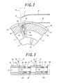
- FIG. 2 is an enlarged view as seen in the direction of arrow A in FIG. 1.
- FIG. 3 is an enlarged sectional view of the apparatus of FIG. 1, showing the region including a chuck.
- FIGS. 1 to 3 A preferred embodiment of the apparatus for producing tire bead cores according to the present invention is shown in FIGS. 1 to 3, wherein reference numeral 11 denotes a horizontal main shaft that is rotatably supported by a drive means, not shown.
- reference numeral 11 denotes a horizontal main shaft that is rotatably supported by a drive means, not shown.
- one end of the main shaft 11 is connected to a motor (not shown) through an endless belt and pulleys, so that the main shaft 11 is driven into rotation as the motor is operated.
- Another end of the main shaft 11 is fixedly secured to a coaxial disc 12.
- the disc 12 has a side surface remote from the main shaft 11, which is provided with a plurality of pairs of guide rails 13 each extending in the radial direction.
- the pairs of guide rails 13 are equidistantly spaced from each other in the circumferential direction.
- Each pair of the guide rails 13 serves to slidably support an arcuate slider 17 via a slide bearing 16.
- the slider 17 has a surface in its radially outer end region, which is remote from the guide rails 13 and to which an arcuate segment 18 is fixedly secured.
- the segments 18 are arranged to as to be radially movable and aligned in the circumferential direction one after the other, exhibiting as a whole a ring shape that is divided into a plurality of portions.
- each segment 18 is formed with at least one circumferential groove 19 having a predetermined cross-section, i.e., two circumferential grooves having a square cross-section, which are spaced from each other in the axial direction.
- the segments 18 as a whole constitute a winding drum 20.
- the shaft 1, the disc 12, as well as the motor, the endless belt and the pulleys (which are not shown), as a whole constitute the rotating means 21 for rotating the winding drum 20 together with the chuck to be described hereinafter.
- Reference numeral 24 denotes a spring box that is fixedly secured to the other end of the main shaft 11 coaxially thereto, having a cylindrical shape with a closed end.
- the spring box 24 has an outer surface axially slidably fitted into a substantially annular movable member 25.
- Reference numeral 26 denotes a plurality of connector links (same in number as the sliders 17), which extend in substantially radial direction and which are arranged in the circumferential direction with an equal angular distance.
- Each connector link 26 has a radially inner end portion that is pivotally connected to the movable member 25 so that the connector link 26 can be swung about the pivot connection.
- Reference numeral 27 denotes brackets each extending axially with one end fixedly secured to the other side surface of the slider 17.
- Each bracket 27 has another end connected to the radially outer end portion of the connector link 26.
- the connector link 26 is situated at a substantially upright position, assuming a smaller inclination angle relative to the radial direction, so that the brackets 27, the sliders 17 and the segments 18 as being guided by the guide rails 13 are synchronously moved radially outwards, thereby increasing the diameter of the winding drum 20.
- an axially movable retainer 30 having an inner collar 29 at one end.
- a compression coil spring 31 is arranged between the collar 29 of the retainer 30 and the bottom wall of the spring box 24 so as to resiliently urge the retainer 30 toward the one side, i.e., toward the main shaft 11.
- An axial slit 32 is formed in the spring box 24 for receiving a pin 33 extending therethrough for connecting the retainer 30 with the movable member 25.
- a radial actuator means 34 such as a cylinder device, for synchronously moving the segments 18 radially inwards or outwards, so as to reduce or increase the outer diameter of the drum 20 to a desired value.
- a bead wire 25 comprised of a steel cord or steel monofilament is spirally wound into plural layers within the circumferential groove 19 in the drum 18, so as to form a bead core 36 having a desired cross-sectional shape, i.e., square shape in the illustrated embodiment.
- the segments 18 are synchronously moved radially inwards by the actuator means 34, so as to reduce the outer diameter of the drum 20 to a value smaller than the inner diameter of the bead core 36.
- a transfer means is then operated to hold the bead core 36 and transfer it to a subsequent station for further processing.
- Reference numeral 40 denotes a support casing in the form of a stepped cylinder, which is arranged between adjacent segments 18 to extend in parallel with the main shaft 11.
- One end of the support casing 40 extends through a radial slit 39 that is formed in the radially outer end portion of the disc 12, and another end of the support casing 40 is formed with two cutouts 41, 42 that are spaced from each other in the axial direction.
- Reference numeral 43 denotes a movable shaft that is axially movably arranged within the support casing 40.
- the movable shaft 43 has an end region provided with two small diameter portions 43a, 43b that are spaced from each other in the axial direction such that the small diameter portion 43a is axially aligned with the cutout 41 and the small diameter portion 43b is axially aligned with the cutout 42.
- Reference numerals 44, 45 denote jaw members that are axially movably fitted over the small diameter portions 43a, 43b of the movable shaft 43, respectively.
- the jaw member 45 and that portion of the support case 40 which is situated between the cutouts 41, 42, jointly constitute another pair of clamp jaws 47 for clamping the leading end of the bear wire 35 to be wound in the circumferential groove 19 on the other side.
- a compression coil spring 49 is arranged between the jaw member 44 and a shoulder portion 48 that is situated at the end portion of the small diameter portion 43a, for axially urging the jaw member 44.
- Another compression coil spring 51 is arranged between the jaw member 45 and a flange 50 that is fixedly secured to the end portion of the movable shaft 43, for axially urging the jaw member 45.
- Reference numeral 54 denotes a transfer rod that is fixedly secured to the end portion of the movable shaft 43.
- a compression coil spring 55 is arranged between the transfer rod 54 and the support casing 40, for axially urging the movable shaft 43 and the transfer rod 54.
- the pairs of clamp jaws 46, 47 are each closed by the urging force of the springs 55, 49, 51 so that when the leading end of the bead wire 35 extending tangentially relative to the drum 20 is situated between the pairs of clamp jaws 46, 47, the leading end of the bead wire 35 is clamped by the respective pairs of clamp jaws 47, 47 axially from both sides.
- the above-mentioned support casing 40, movable shaft 43, clamp jaws 64, 47, spring 49, flange 50, spring 51, transfer rod 54 and spring 55 jointly constitute a chuck 56 arranged between neighboring segments 18 and having pairs of clamp jaws 64, 47 for clamping the leading end of the bead wire 35 that extends tangentially relative to the winding drum 20.
- the disc 12 on its surface remote from the radial actuator means 34 is provided with a pair of guide rails 60 each extending in the radial direction.
- a slide bearing 61 is slidably engaged with the guide rail 60 and secured to a connector plate 62 that, in turn, is fixedly secured to the support casing 40.
- Reference numeral 63 denotes a connector link that normally extends in parallel with the above-mentioned connector link 26.
- the connector link 63 has a radially inner end portion that is connected to the movable member 25.
- Reference numeral 64 denotes a bracket that is in parallel with the bracket 27 of which one end extends through the slit 39.
- the bracket 64 has one end portion that is fixedly secured to the connector plate 62, and another end portion that is connected to the radially outer end portion of the connector link 63.
- the above-mentioned connector plate 62, connector link 63 and bracket 64 jointly constitute a connector 65 for connecting the chuck 56 and the radial actuator means 34.
- the chuck 56 may be connected to one of the neighboring segments 18 through an appropriate connector element.
- Such an arrangement also is simple and less costly in structure.
- Reference numeral 68 denotes a vertical post that is arranged immediately above the chuck 56.
- the post 68 has a side surface provided with a guide rail 69 that extend vertically.
- Reference numeral 70 denotes a carriage having a slide bearing 71 that is slidably engaged with the guide rail 69 so that the carriage 70 can be moved vertically along the post 68.
- the carriage 70 has two projections 70a projecting downwards, which are spaced from each other by a distance that is equal to the axial distance between the circumferential grooves 19.
- Each projection 70a of the carriage 70 has a bottom end portion connected to the upper end portion of a guide member 72 in the form of a strip that extends radially.
- the guide members 72 are arranged on the radially outer side of the pairs of clamp jaws 46, 47 or, more specifically, jaw members 44, 45.
- the guide members 72 are made of permanent magnet at least partly, and preferably entirely as in the illustrated embodiment.
- the bead wire 35 made of ferromagnetic material can be effectively attracted by the guide members 72 so that the leading end of the bead wire 35 is effectively maintained in contact with the guide member 72. It is therefore possible positively to guide the leading end of the bead wire to a position between the pair of clamp jaws 46 or the pair of clamp jaws 47.
- Reference numeral 73 denotes an actuator in the form of a vertical cylinder device that is secured to the vertical post 68 at a position above the carriage 70.
- the cylinder device 73 has a piston rod 74 with a tip end that is connected to the carriage 70.
- two bead wires 35 extending substantially tangentially relative to the winding drum 20 are moved in a translation manner toward the chuck 56, from the solid line position to the imaginary line position as shown in FIG. 2, so that the leading ends of the bead wires 35 approach the clamp jaws 46, 47. It is assumed that the leading ends of the bead wires 35 have already been subjected to plastic deformation, by a forming device (not shown), so that the leading ends of the bead wires 35 are bent to have a radius of curvature that corresponds substantially to the inner diameter of the bead core 36.
- the main shaft 11 is then rotated by the motor (not shown), jointly with the support disc 12, the winding drum 20 and the chuck 56 clamping the leading ends of the bead wires 35.
- the bead wires 35 are helically wound in the circumferential grooves 19 of the winding drum 20 while axially moving back and forth and thereby forming a plurality of layers, so as to simultaneously produce bead cores 36 having a square cross-section.
- the bead wire 35 is cut at a predetermined cut position by a cutter, while holding the bead wire 35 at a location adjacent to the cut position by means of a holder.
- the actuator for the transfer rod 54 is operated to move the transfer rod 54, the movable shaft 43 and the jaw members 44, 45 against the resilient force of the springs 49, 51, 55, so as to open the clamp jaws 46, 47 and thereby release the leading ends of the bead wires 35.
- the actuator means 34 associated with the movable member 25 is then operated so as to move the movable member 25 against the resilient force of the spring 31, i.e., toward right in FIG. 2, together with the retainer 30 and the connector pin 33.
- the connector links 26, 63 undergo swinging movement about their pivoted inner ends, gradually increasing the inclination angle relative to the radial direction.
- the segments 18 of the winding drum 20 are synchronously moved radially inwards, together with the sliders 17, while being guided by the guide rails 13.
- the chuck 56 is also moved radially inwards, together with the connector plate 62, while being guided by the guide rail 60.
- Such inward movement of the segments 18 and the chuck 56 is stopped when the outer diameter of the winding drum 20 reaches a value that is smaller than the inner diameter of the bead core 36.
- the bead cores 36 produced as above are held by the transfer means, not shown, and transferred to a subsequent station for further processing.
- the operation of the actuator means 34 is then stopped so that the axial thrust is removed from the movable member 25.
- the movable member 25 is returned to its stroke end position by the spring 31, so that the segments 18 and the chuck 56 are moved back radially outwards to the original positions.
- the present invention provides improved method and apparatus for producing bead cores, wherein the leading end of the bead wire can be readily and positively clamped by the chuck, even when the leading end of the bead wire is bent to have a predetermined radius of curvature.
- the radial movement of the chuck and the opening/closing operation of the chuck are performed at different timings as in the illustrated embodiment.
- the arrangement may be modified so that the chuck is closed during its radial inward movement and opened during its radial outward movement.
Landscapes
- Engineering & Computer Science (AREA)
- Mechanical Engineering (AREA)
- Tyre Moulding (AREA)
Abstract
Description
to the original positions.
Claims (8)
- A method for producing tire bead cores, comprising:providing a bead core winding drum (20) that includes a plurality of arcuate segments (18) aligned in a circumferential direction of the winding drum, said segments each being radially movable and having an outer periphery formed with a circumferential groove (19); and a chuck (56) arranged between neighbouring segments and having a pair of clamp jaws (46;47) for clamping a leading end of a bead wire (35) that extends in a tangential direction relative to said winding drum;guiding a bead wire (35), which extends in a tangential direction of the winding drum (20), by a guide means (72) that extends radially relative to the winding drum, and moving the guide means toward the clamp jaws (46;47) to cause a translation movement of a bead wire to a position between the clamp jaws and then clamping a leading end of the bead wire by the chuck (56);rotating the winding drum (20) together with the chuck (56) so that the bead wire (35) with its leading end clamped by the chuck is helically wound in the circumferential groove (19) as a plurality of layers, thereby forming a bead core (36) having a predetermined cross-section; andsynchronously moving the segments (18) radially inwards, after formation of the bead core (36), so as to reduce an outer diameter of the drum (20) to a value smaller than an inner diameter of the bead core.
- A method as claimed in claim 1, characterized in that said chuck (56) is radially moved together with the segments (18) as the latter are synchronously moved radially.
- Apparatus for producing tire beads cores, comprising:a bead core winding drum (20) including a plurality of arcuate segments (18) that are aligned in a circumferential direction of the winding drum, said segments each being radially movable and having an outer periphery formed with a circumferential groove (19);a chuck (56) arranged between neighbouring segments (18) and having a pair of clamp jaws (46;47) for clamping a leading end of a bead wire (35) that extends in a tangential direction relative to said winding drum (20);a guide means (72) for the leading end of the bead wire (35), said guide means being arranged on a radially outer side of the clamp jaws (46;47) and extending substantially radially;a moving means (73,74) for moving the guide means (72) toward and away from the clamp jaws (46;47), said moving means being operative so as to move the guide means toward the clamp jaws and subsequently cause a translation movement of the leading end of the bead wire (35) in contact therewith, to a position between the clamp jaws;a rotating means (21) for rotating the winding drum (20) together with the chuck (56) so that the bead wire (35) with its leading end clamped by the chuck is helically wound in the circumferential groove (19) as a plurality of layers, thereby forming a bead core (36) having a predetermined cross-section; anda radial actuator means (34) for synchronously moving the segments (18) radially inwards, after formation of the bead core (36), so as to reduce an outer diameter of the drum (20) to a value smaller than an inner diameter of the bead core.
- Apparatus as claimed in claim 3, characterized in that said chuck (56) is radially movable together with the segments (18), as the segments are synchronously moved radially by the radial actuator means (34).
- Apparatus as claimed in claim 4, characterized by further comprising a connector (65) for connecting said chuck (56) and said radial actuator means (34) with each other so that said chuck is moved radially together with the segments (18) in operation of the radial actuator means.
- Apparatus as claimed in claim 4, characterized in that said chuck (56) is secured to the segments (18) so as to be radially movable together with the segments in operation of the radial actuator means (34).
- Apparatus as claimed in any of claims 3 to 6, characterized in that said guide means (72) comprises an attraction means for attracting the bead wire (35) such that the bead wire is brought into contact with the guide means.
- Apparatus as claimed in claim 7, characterized in that the attraction means comprises a magnet.
Applications Claiming Priority (2)
| Application Number | Priority Date | Filing Date | Title |
|---|---|---|---|
| JP2001356912 | 2001-11-22 | ||
| JP2001356912A JP2003154581A (en) | 2001-11-22 | 2001-11-22 | Method and apparatus for manufacturing bead core for tire |
Publications (3)
| Publication Number | Publication Date |
|---|---|
| EP1314545A2 true EP1314545A2 (en) | 2003-05-28 |
| EP1314545A3 EP1314545A3 (en) | 2005-01-12 |
| EP1314545B1 EP1314545B1 (en) | 2007-10-31 |
Family
ID=19168338
Family Applications (1)
| Application Number | Title | Priority Date | Filing Date |
|---|---|---|---|
| EP02258070A Expired - Lifetime EP1314545B1 (en) | 2001-11-22 | 2002-11-22 | Method and apparatus for producing tire bead cores |
Country Status (5)
| Country | Link |
|---|---|
| US (1) | US7048820B2 (en) |
| EP (1) | EP1314545B1 (en) |
| JP (1) | JP2003154581A (en) |
| DE (1) | DE60223224T2 (en) |
| ES (1) | ES2295294T3 (en) |
Cited By (3)
| Publication number | Priority date | Publication date | Assignee | Title |
|---|---|---|---|---|
| EP2055467A1 (en) * | 2007-11-05 | 2009-05-06 | Hankook Tire Co., Ltd. | Bead structure building apparatus in green tire buidling machine |
| CN106660288A (en) * | 2014-08-27 | 2017-05-10 | 不二精工株式会社 | Clamping device |
| CN112118957A (en) * | 2018-05-14 | 2020-12-22 | 米其林集团总公司 | Method and apparatus for manufacturing braided bead wires for pneumatic tires comprising folding the excess braided wire length |
Families Citing this family (9)
| Publication number | Priority date | Publication date | Assignee | Title |
|---|---|---|---|---|
| JP3694890B2 (en) * | 2000-06-05 | 2005-09-14 | 富士ゼロックス株式会社 | Endless belt manufacturing method, endless belt and image forming apparatus |
| JP2010173131A (en) * | 2009-01-28 | 2010-08-12 | Bridgestone Corp | Bead-core molding apparatus and bead-core molding method |
| CN104245179B (en) | 2012-04-24 | 2016-03-02 | 不二精工株式会社 | Wire loop manufacturing installation |
| KR101946676B1 (en) | 2012-05-30 | 2019-02-11 | 후지 세이코 가부시키가이샤 | Winding device |
| IN2014MN02519A (en) * | 2012-06-12 | 2015-07-17 | Fuji Seiko Co Ltd | |
| DE102013108184B3 (en) * | 2013-07-31 | 2014-03-27 | GfA De Pryck & Co. Gesellschaft für Automatisierungstechnik mbH | Winding machine for manufacturing wire core for tire of vehicle, has transportation drive that is provided for driving escapement wheel and is synchronized with winding drive of winding pulley used to roll winding material to wire core |
| DE102019122233B3 (en) * | 2019-08-19 | 2021-01-14 | GfA De Pryck & Co. Gesellschaft für Automatisierungstechnik mbH | Core winder, production line and process for manufacturing wire cores |
| JP2021074883A (en) * | 2019-11-05 | 2021-05-20 | 住友ゴム工業株式会社 | Wire bundle manufacturing equipment |
| CN111231392B (en) * | 2020-04-08 | 2024-12-03 | 江阴市特象机械有限公司 | Automatic steel ring wrapping machine |
Family Cites Families (9)
| Publication number | Priority date | Publication date | Assignee | Title |
|---|---|---|---|---|
| US2979109A (en) * | 1956-12-10 | 1961-04-11 | Firestone Tire & Rubber Co | Method and apparatus for forming tire bead grommets |
| US3475255A (en) * | 1965-03-24 | 1969-10-28 | Nat Standard Co | Automatic tire bead making apparatus |
| IN157253B (en) * | 1980-10-16 | 1986-02-15 | Bates W & A Ltd | |
| FR2677578A1 (en) * | 1991-06-17 | 1992-12-18 | Sedepro | PROCESS FOR THE MANUFACTURE OF A TIRE AND MACHINES FOR THE IMPLEMENTATION OF THIS PROCESS. |
| JPH10166473A (en) * | 1996-12-06 | 1998-06-23 | Mitsubishi Heavy Ind Ltd | Bead former |
| US5882458A (en) * | 1997-07-24 | 1999-03-16 | Bartell Machinery Systems,Llc | Tire bead forming method and apparatus |
| JPH11105156A (en) * | 1997-10-08 | 1999-04-20 | Yokohama Rubber Co Ltd:The | Suction device for tire bead part in post cure inflator |
| JP3909139B2 (en) * | 1998-01-20 | 2007-04-25 | 住友ゴム工業株式会社 | Bead core forming equipment |
| GB2359791A (en) | 2000-02-29 | 2001-09-05 | A R T | A former for winding elongate material, e.g. tyre bead wire |
-
2001
- 2001-11-22 JP JP2001356912A patent/JP2003154581A/en not_active Withdrawn
-
2002
- 2002-11-21 US US10/300,840 patent/US7048820B2/en not_active Expired - Fee Related
- 2002-11-22 DE DE60223224T patent/DE60223224T2/en not_active Expired - Lifetime
- 2002-11-22 ES ES02258070T patent/ES2295294T3/en not_active Expired - Lifetime
- 2002-11-22 EP EP02258070A patent/EP1314545B1/en not_active Expired - Lifetime
Cited By (4)
| Publication number | Priority date | Publication date | Assignee | Title |
|---|---|---|---|---|
| EP2055467A1 (en) * | 2007-11-05 | 2009-05-06 | Hankook Tire Co., Ltd. | Bead structure building apparatus in green tire buidling machine |
| CN106660288A (en) * | 2014-08-27 | 2017-05-10 | 不二精工株式会社 | Clamping device |
| CN106660288B (en) * | 2014-08-27 | 2019-05-28 | 不二精工株式会社 | Clamping device |
| CN112118957A (en) * | 2018-05-14 | 2020-12-22 | 米其林集团总公司 | Method and apparatus for manufacturing braided bead wires for pneumatic tires comprising folding the excess braided wire length |
Also Published As
| Publication number | Publication date |
|---|---|
| US7048820B2 (en) | 2006-05-23 |
| US20030116254A1 (en) | 2003-06-26 |
| DE60223224D1 (en) | 2007-12-13 |
| EP1314545B1 (en) | 2007-10-31 |
| DE60223224T2 (en) | 2008-08-07 |
| EP1314545A3 (en) | 2005-01-12 |
| JP2003154581A (en) | 2003-05-27 |
| ES2295294T3 (en) | 2008-04-16 |
Similar Documents
| Publication | Publication Date | Title |
|---|---|---|
| US7048820B2 (en) | Method and apparatus for producing tire bead cores | |
| US4409872A (en) | Apparatus for feeding reinforcing layers in tire manufacture | |
| EP0026498B1 (en) | Improvements to the apparatuses for applying elastomeric fillers to tire bead cores | |
| EP1272338B1 (en) | Tyre drum provided with a turn-up device | |
| SU1264832A3 (en) | Device for vulcanizing tyres | |
| EP0995584B1 (en) | Bead wire winding device and method | |
| CN207723394U (en) | A kind of bending mechanism of spring coiling machine | |
| US6363988B1 (en) | Manufacturing apparatus for single-wire bead | |
| US5051149A (en) | Tire building apparatus including bead supply means for bead setters | |
| EP0639447B1 (en) | A tyre former capable of expanding and contracting in an axial direction | |
| US3472461A (en) | Method and apparatus for anchoring one end of continuously advancing material | |
| RU2005141424A (en) | MOBILE UNIT FOR ROLLED MATERIAL HAVING AN IMPROVED CONTROL SYSTEM FOR WINDING OF WINDS | |
| EP1264681A1 (en) | Bead holder assembly and method of holding and positioning a tire bead | |
| US6949213B1 (en) | Vulcanizing mold for pneumatic tires | |
| US5650034A (en) | Transfer ring for toroidal carcasses | |
| US1921579A (en) | Tire forming device | |
| CA1198348A (en) | Bead jamming or crimping apparatus | |
| US4030673A (en) | Double wire-winding machine with automatic transfer | |
| US2917087A (en) | Apparatus for winding tire beads | |
| US20030029573A1 (en) | Formation of tyre beads or the like | |
| JP2009012212A (en) | Apparatus for producing bead-core for tire | |
| EP0037702B1 (en) | Tire curing press and tire curing method | |
| JP2004064829A (en) | Winding device | |
| EP1106322A1 (en) | Vulcanizing mold for pneumatic tires | |
| CN114906669B (en) | Automatic wire coiling machine |
Legal Events
| Date | Code | Title | Description |
|---|---|---|---|
| PUAI | Public reference made under article 153(3) epc to a published international application that has entered the european phase |
Free format text: ORIGINAL CODE: 0009012 |
|
| AK | Designated contracting states |
Designated state(s): AT BE BG CH CY CZ DE DK EE ES FI FR GB GR IE IT LI LU MC NL PT SE SK TR |
|
| AX | Request for extension of the european patent |
Extension state: AL LT LV MK RO SI |
|
| PUAL | Search report despatched |
Free format text: ORIGINAL CODE: 0009013 |
|
| AK | Designated contracting states |
Kind code of ref document: A3 Designated state(s): AT BE BG CH CY CZ DE DK EE ES FI FR GB GR IE IT LI LU MC NL PT SE SK TR |
|
| AX | Request for extension of the european patent |
Extension state: AL LT LV MK RO SI |
|
| 17P | Request for examination filed |
Effective date: 20050524 |
|
| AKX | Designation fees paid |
Designated state(s): DE ES FR GB IT |
|
| 17Q | First examination report despatched |
Effective date: 20060112 |
|
| GRAP | Despatch of communication of intention to grant a patent |
Free format text: ORIGINAL CODE: EPIDOSNIGR1 |
|
| GRAS | Grant fee paid |
Free format text: ORIGINAL CODE: EPIDOSNIGR3 |
|
| GRAA | (expected) grant |
Free format text: ORIGINAL CODE: 0009210 |
|
| AK | Designated contracting states |
Kind code of ref document: B1 Designated state(s): DE ES FR GB IT |
|
| REG | Reference to a national code |
Ref country code: GB Ref legal event code: FG4D |
|
| REF | Corresponds to: |
Ref document number: 60223224 Country of ref document: DE Date of ref document: 20071213 Kind code of ref document: P |
|
| REG | Reference to a national code |
Ref country code: ES Ref legal event code: FG2A Ref document number: 2295294 Country of ref document: ES Kind code of ref document: T3 |
|
| ET | Fr: translation filed | ||
| PLBE | No opposition filed within time limit |
Free format text: ORIGINAL CODE: 0009261 |
|
| STAA | Information on the status of an ep patent application or granted ep patent |
Free format text: STATUS: NO OPPOSITION FILED WITHIN TIME LIMIT |
|
| 26N | No opposition filed |
Effective date: 20080801 |
|
| REG | Reference to a national code |
Ref country code: FR Ref legal event code: CA Effective date: 20140812 |
|
| REG | Reference to a national code |
Ref country code: DE Ref legal event code: R081 Ref document number: 60223224 Country of ref document: DE Owner name: BRIDGESTONE CORPORATION, JP Free format text: FORMER OWNER: BRIDGESTONE CORP., TOKIO/TOKYO, JP Effective date: 20140828 |
|
| REG | Reference to a national code |
Ref country code: FR Ref legal event code: PLFP Year of fee payment: 14 |
|
| REG | Reference to a national code |
Ref country code: FR Ref legal event code: PLFP Year of fee payment: 15 |
|
| PGFP | Annual fee paid to national office [announced via postgrant information from national office to epo] |
Ref country code: GB Payment date: 20161122 Year of fee payment: 15 Ref country code: FR Payment date: 20161118 Year of fee payment: 15 Ref country code: DE Payment date: 20161121 Year of fee payment: 15 |
|
| PGFP | Annual fee paid to national office [announced via postgrant information from national office to epo] |
Ref country code: ES Payment date: 20161114 Year of fee payment: 15 Ref country code: IT Payment date: 20161123 Year of fee payment: 15 |
|
| REG | Reference to a national code |
Ref country code: DE Ref legal event code: R119 Ref document number: 60223224 Country of ref document: DE |
|
| GBPC | Gb: european patent ceased through non-payment of renewal fee |
Effective date: 20171122 |
|
| REG | Reference to a national code |
Ref country code: FR Ref legal event code: ST Effective date: 20180731 |
|
| PG25 | Lapsed in a contracting state [announced via postgrant information from national office to epo] |
Ref country code: FR Free format text: LAPSE BECAUSE OF NON-PAYMENT OF DUE FEES Effective date: 20171130 Ref country code: IT Free format text: LAPSE BECAUSE OF NON-PAYMENT OF DUE FEES Effective date: 20171122 Ref country code: DE Free format text: LAPSE BECAUSE OF NON-PAYMENT OF DUE FEES Effective date: 20180602 |
|
| PG25 | Lapsed in a contracting state [announced via postgrant information from national office to epo] |
Ref country code: GB Free format text: LAPSE BECAUSE OF NON-PAYMENT OF DUE FEES Effective date: 20171122 |
|
| PG25 | Lapsed in a contracting state [announced via postgrant information from national office to epo] |
Ref country code: ES Free format text: LAPSE BECAUSE OF NON-PAYMENT OF DUE FEES Effective date: 20171123 |