US6949213B1 - Vulcanizing mold for pneumatic tires - Google Patents
Vulcanizing mold for pneumatic tires Download PDFInfo
- Publication number
- US6949213B1 US6949213B1 US09/431,154 US43115499A US6949213B1 US 6949213 B1 US6949213 B1 US 6949213B1 US 43115499 A US43115499 A US 43115499A US 6949213 B1 US6949213 B1 US 6949213B1
- Authority
- US
- United States
- Prior art keywords
- segments
- mold members
- cam ring
- mold
- sidewall
- Prior art date
- Legal status (The legal status is an assumption and is not a legal conclusion. Google has not performed a legal analysis and makes no representation as to the accuracy of the status listed.)
- Expired - Fee Related, expires
Links
Images


Classifications
-
- B—PERFORMING OPERATIONS; TRANSPORTING
- B29—WORKING OF PLASTICS; WORKING OF SUBSTANCES IN A PLASTIC STATE IN GENERAL
- B29D—PRODUCING PARTICULAR ARTICLES FROM PLASTICS OR FROM SUBSTANCES IN A PLASTIC STATE
- B29D30/00—Producing pneumatic or solid tyres or parts thereof
- B29D30/06—Pneumatic tyres or parts thereof (e.g. produced by casting, moulding, compression moulding, injection moulding, centrifugal casting)
- B29D30/0601—Vulcanising tyres; Vulcanising presses for tyres
- B29D30/0606—Vulcanising moulds not integral with vulcanising presses
- B29D30/0629—Vulcanising moulds not integral with vulcanising presses with radially movable sectors
- B29D2030/063—Vulcanising moulds not integral with vulcanising presses with radially movable sectors the moulds being split in upper and lower halves
Definitions
- the present invention relates to a vulcanizing mold and vulcanizing method for pneumatic tires.
- a full-type mold has inner surface portions for forming the tread portion and side portions of a tire, and is divided into upper and lower mold halves at a parting plane which corresponds to the tire equatorial plane. These mold halves are displaceable in the vertical direction toward and away from each other for closing and opening the mold, respectively.
- the full-type mold is advantageous in that it is simple in structure, small in size and inexpensive.
- the mold upon removal of a product tire out of the mold after completion of vulcanization, the mold is opened only by a relative vertical displacement of the upper and lower mold halves, and the full-type mold may thereby give rise to formation of defective products depending upon the tread pattern.
- the projections or ridges provided on the mold inner surface for forming the tread portion of the tire may exert excessive shearing forces to the tread land regions, thereby causing such problem that defects tend to be formed in the tread land regions such as nicks and/or cracks.
- a split-type mold is comprised of upper and lower sidewall mold members which are vertically displaceable relative to each other, and a tread mold member which is divided into a plurality of arcuate segments arranged successively in the circumferential direction. The segments of the tread mold member are radially displaceable to increase or decrease the diameter.
- a vulcanizing mold for pneumatic tires comprising: upper and lower base plates; upper and lower sidewall mold members for forming tire sidewall portions, said upper and lower sidewall mold members being attached to said upper and lower base plates, respectively; upper and lower tread mold members for forming a tire tread portion, said upper and lower tread mold members being attached to said upper and lower base plates, respectively; said upper and lower tread mold members being constituted of upper segments and lower segments, respectively, said upper and lower segments being displaceable only radially relative to said upper and lower sidewall mold members, respectively; and a single cam ring which is adapted to be displaced independently of approaching displacements of said sidewall mold members toward each other, to thereby simultaneously displace all of said upper and lower segments radially inwards while said upper and lower segments are in abutment with each other.
- the upper and lower tread mold members forming a pair are constituted of the upper segments and lower segments, respectively, which can be radially displaced to decrease or increase the diameter.
- the mold is opened to remove the product tire from the mold, all of the segments are displaced radially outwards to increase the diameter by virtue of the operation of the cam ring.
- the mold is then opened by vertically displacing the upper and lower tread mold members away from each other, for allowing removal of the tire from the mold.
- the tire can be positively removed from the mold without forming defects in the tread land region such as nicks and/or cracks.
- the present invention serves to minimize the required displacement amount of the respective segments radially outwards, within such a degree that the maximum projections or ridges on the inner surface of the segments can be fully disengaged from the recesses in the tread. It is therefore possible to effectively avoid undesirable increase in the outer diameter of the mold as a whole.
- the upper and lower segments are engaged with the upper and lower base plates, respectively, such that they are radially displaceable relative to respective one of the sidewall mold members, either directly or indirectly through slide guide members which may be provided on the sidewall mold members.
- slide guide members which may be provided on the sidewall mold members.
- the cam ring is engageable with both of the upper and lower segments of the upper and lower base plates sides.
- the cam ring is engageable with both of the upper and lower segments of the upper and lower base plates sides.
- the upper segments are always in engagement with the cam ring on radially inner side thereof.
- the cam ring has an initial posture in which it is in contact with the upper segments along the entire height thereof.
- abutment members for defining the upper limit position of the cam ring relative to the upper base plate.
- a vulcanizing method for pneumatic tires with a vulcanizing mold which comprises: (i) upper and lower base plates; (ii) upper and lower sidewall mold members attached to said upper and lower base plates, respectively; and (iii) upper and lower tread mold members attached to said upper and lower base plates, respectively; (iv) said upper and lower tread mold members being constituted of upper segments and lower segments, respectively, which can be radially expanded and contracted relative to the upper and lower sidewall mold members, respectively.
- the upper and lower sidewall mold members are displaced toward each other so that the upper and lower segments are brought into abutment with each other.
- a single cam ring is operated to simultaneously displace all of the segments radially inwards and relative to the upper and lower sidewall mold members, with the upper segments in abutment with the lower segments in order to perform the required pattern formation on the tread portion of a green tire.
- the formation at the side portions of a green tire is performed before the formation at the tread portion of the green tire, by means of the sidewall mold members have forming inner surfaces which are substantially free from unevenness. It is thus possible to significantly reduce the flow of the rubber material due to the formation, effectively preventing the flow of the rubber material into a space, if any, between the sidewall mold members and the segments on their radially outer sides. As a result, it is possible to advantageously prevent the rubber material from biting between the sidewall mold members and the segments which are being displaced radially inwards, for performing subsequent formation at the tread portion of the green tire.
- FIG. 1 is a schematic sectional view showing the vulcanizing mold according to the above-mentioned prior art.
- FIG. 2 is a schematic sectional view showing the vulcanizing mold according to one embodiment of the present invention.
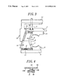
- FIG. 3 is a schematic sectional view showing the vulcanizing mold of FIG. 2 , wherein the segments have been radially expanded to the respective outermost positions;
- FIG. 4 is a fragmentary sectional view showing the connection between the cam ring and the segment.
- FIG. 5 is a schematic sectional view showing the vulcanizing mold of FIG. 2 , wherein the upper segments are vertically moved away from the lower segments.
- FIG. 2 is a longitudinal sectional view of an essential part of an embodiment of the present invention, wherein reference numerals 1 and 2 designate upper base plate and lower base plate, respectively.
- the upper base plate 1 can be displaced vertically upwards and downwards relative to the lower base plate 2 also acting as a lower platen, under the operation of a cylinder rod 3 of a cylinder device (not shown).
- Upper and lower sidewall mold members 4 , 5 which contribute to the formation of the outer surfaces of tire sidewall portions are provided by directly fixing them to the upper and lower base plates 1 , 2 , respectively.
- upper and lower tread mold members 6 , 7 which contribute to the formation of the tire tread surface, on the outer peripheral sides of the sidewall mold members 4 , 5 , respectively.
- the upper and lower tread mold members 6 , 7 are constituted of a plurality of segments 8 , 9 which can be radially displaced relative to the sidewall mold members 4 , 5 .
- the radial displacement of the segments 8 , 9 can be smoothly and assuredly performed, by engaging the upper end portions and lower end portions of the segments 8 , 9 into T-shaped grooves in slide guide brackets 10 , 11 which are attached to the upper and lower base plates 1 , 2 , respectively.
- the T-shaped grooves are formed to extend radially relative to the sidewall mold members 4 , 5 , and serve to guide the radial sliding displacement of the segments 8 , 9 and also to prevent withdrawal of the segments 8 , 9 from the slide guide brackets 10 , 11 . In this way, the upper and lower segments 8 , 9 are allowed to be displaced only radially, relative to the respective sidewall mold members 4 , 5 .
- the segments 8 , 9 can be radially displaced to predetermined positions where the forming surfaces of the segments 8 , 9 are aligned with the corresponding forming surfaces of the sidewall mold members 4 , 5 , respectively, without any gaps therebetween.
- a cam ring 13 is attached to an upper platen 12 which is adapted to be displaced vertically upwards and downwards with a driving means independent from that for the upper base plate 1 .
- the cam ring 13 has an inner peripheral surface which projects toward the segments 8 , 9 and contacts them. Such inner surface of the cam ring 13 forms a tapered cam surface 13 a having an inner diameter which progressively increases downwards.
- the outer peripheral surfaces of the segments 8 , 9 are provided with driven surfaces 8 a , 9 a having tapered angles corresponding to the tapered cam surface 13 a . These driven surfaces 8 a , 9 a are capable of achieving a surface contact with the tapered cam surface 13 a.
- the driven surfaces 8 a of the upper segments 8 are formed with T-shaped grooves 8 b which extend in the vertical direction along the entire height of the segments 8 .
- the cam ring 13 is provided with projections 13 b which are precisely fitted in the T-shaped grooves 8 b , respectively, so as to engage the cam ring 13 with the segments 8 .
- the driven surfaces 9 a of the lower segments 9 are also formed with T-shaped grooves having shapes and dimensions corresponding to the T-shaped grooves 8 b in the upper segments 8 .
- the segments 8 , 9 can be returned precisely to their outer limit positions, under the engagement with the projections 13 b of the respective T-shaped grooves. Furthermore, it is also possible to prevent unintended expansion or contraction of the mold, i.e., unintended radial displacements of the segments 8 , 9 since they are in engagement with the projections 13 b.
- the lower segments 9 can be disengaged from the projections 13 b depending upon a stroke position of the cam ring 13 .
- return springs S are provided for urging the segments 9 radially outwards, i.e., toward their outer limit positions, for assuring positive and smooth engagement of the projections 13 b into the respective T-shaped grooves in the lower segments 9 .
- the cam ring 13 is provided with a shoulder 14 which is brought into abutment with the upper base plate 1 to which the segments 8 are attached, at an upper limit position of the cam ring 13 relative to the segments 8 .
- the mold opening process can be continued by further displacing the upper base plate 1 and upper platen 12 upwards in a synchronized manner, under the operation of respective vertical drive means provided independently from each other. Nonetheless, it is also possible to lift the upper base plate 1 through the cam ring 13 by operating the vertical drive means for the upper platen 12 only, while stopping the operation of a cylinder (not shown) forming the vertical drive means for the upper base plate 1 . In this case, it is unnecessary to control the upper base plate 1 and upper platen 12 in a synchronized manner.
- a green tire G positioned on a hard core or bladder within a mold which is in a fully opened position. Then, formation of side portions of a green tire G is started by the sidewall mold members 4 , 5 , when the vertical drive means for the upper platen 12 is operated to displace the upper base plate 1 downwards through the cam ring 13 , and thereby displace the sidewall mold member 4 and upper segments 8 downwards, or when the cylinder rod 3 is extended to directly displace the base plate 1 downwards while rendering the cam ring 13 and platen 12 to follow the downward displacement of base plate 1 .
- FIG. 2 shows a state where the segments 8 , 9 have reached their inner limit positions and the formation of the tread portion has been completed.
- the inner peripheral surfaces of the segments 8 , 9 abut against the outer peripheral surfaces of the sidewall mold members 4 , 5 , respectively.
- the rubber material flows mainly in a direction toward the tread portion, because the forming surfaces of the sidewall mold members 4 , 5 do not have noticeable unevenness. It is thus possible to effectively prevent undesired flow of the rubber material into a space, if any, between the outer peripheral surfaces of the sidewall mold members 4 , 5 and the inner peripheral surfaces of the segments 8 , 9 .
- the rubber material is prevented from biting between the segments 8 , 9 and the sidewall mold members 4 , 5 at the time of completion of the tread portion.
- the green tire G as formed in this way is processed into a product tire, by performing vulcanization of the green tire G under predetermined temperature and pressure conditions a predetermined period of time.
- the cam ring 13 is firstly elevated while pressing the upper base plate 1 by the cylinder rod 3 , to thereby simultaneously displace the segments 8 , 9 radially outwards, until the shoulder 14 of the cylinder rod 3 is brought into abutment with the upper base plate 1 as shown in FIG. 3 .
- the segments 8 , 9 are displaced radially outwards relative to the product tire, and the projections or ridges on the forming surfaces of segments 8 , 9 can be smoothly disengaged from recesses in the tread portion.
- the land regions in the tread portion are not applied with shearing forces by the projections or ridges of the segments 8 , 9 , it is possible to preventing formation of defects such as of nicks or cracks at the land regions.
- the upper and lower tread mold members 6 , 7 constituted of the respective segments 8 , 9 are independent from each other in the vertical direction. Therefore, the tread mold members 6 , 7 can be largely separated from each other upon mold opening. The amount of the radial displacement of the segments 8 , 9 can be minimized within a limit in which the projections or ridges of the forming surfaces can be fully disengaged from the tread portion. Also in this way, the separation of the tread mold members 6 , 7 in a vertical direction can be smoothly performed without interfering with the tread portion, upon removal of the product tire.
- the outer dimension of the mold according to the present invention can be significantly reduced as compared to the prior art in which the segments are required to be radially displaced over a relatively longer distance.
- the reduced radial displacement amount of the segments 8 , 9 results in a reduced the stroke amount of the cam ring 13 and thus contributes to reduce the vertical dimension of the mold.
Landscapes
- Engineering & Computer Science (AREA)
- Mechanical Engineering (AREA)
- Moulds For Moulding Plastics Or The Like (AREA)
- Heating, Cooling, Or Curing Plastics Or The Like In General (AREA)
Abstract
Description
Claims (5)
Applications Claiming Priority (1)
| Application Number | Priority Date | Filing Date | Title |
|---|---|---|---|
| JP10311605A JP2000135715A (en) | 1998-11-02 | 1998-11-02 | Mold for vulcanization of tire and method for vulcanization molding |
Publications (1)
| Publication Number | Publication Date |
|---|---|
| US6949213B1 true US6949213B1 (en) | 2005-09-27 |
Family
ID=18019273
Family Applications (1)
| Application Number | Title | Priority Date | Filing Date |
|---|---|---|---|
| US09/431,154 Expired - Fee Related US6949213B1 (en) | 1998-11-02 | 1999-11-01 | Vulcanizing mold for pneumatic tires |
Country Status (2)
| Country | Link |
|---|---|
| US (1) | US6949213B1 (en) |
| JP (1) | JP2000135715A (en) |
Cited By (7)
| Publication number | Priority date | Publication date | Assignee | Title |
|---|---|---|---|---|
| US20060125147A1 (en) * | 2004-12-03 | 2006-06-15 | Bachochin Todd A | Segmented tire mold for off-road-vehicle tires |
| WO2008155782A1 (en) | 2007-06-18 | 2008-12-24 | Mai S.P.A. | Tyre vulcanising press |
| US20100140847A1 (en) * | 2007-05-10 | 2010-06-10 | Mario Secchi | Process and apparatus forr vulcazation and moulding of vehicle tyres |
| US20100303941A1 (en) * | 2006-11-27 | 2010-12-02 | Mario Secchi | Apparatus for vulcanization and moulding of vehicle tyres |
| US20110117229A1 (en) * | 2009-11-18 | 2011-05-19 | Todd Andrew Bachochin | Segmented tire mold |
| US20170225418A1 (en) * | 2014-07-25 | 2017-08-10 | Compagnie Generale Des Etablissements Michelin | Tire vulcanizing mold with optimized closing |
| US10166733B2 (en) * | 2017-04-17 | 2019-01-01 | Bridgestone Americas Tire Operations, Llc | Expansion control device and tire mold using same |
Families Citing this family (5)
| Publication number | Priority date | Publication date | Assignee | Title |
|---|---|---|---|---|
| JP4603709B2 (en) * | 2001-03-05 | 2010-12-22 | 株式会社ブリヂストン | Tire vulcanization mold and tire manufacturing method |
| JP4785552B2 (en) * | 2006-02-13 | 2011-10-05 | 株式会社ブリヂストン | Pneumatic tire |
| CN108357030A (en) * | 2018-04-27 | 2018-08-03 | 宫达 | Tyre adjustable die position-limit mechanism and tyre adjustable die |
| JP7234752B2 (en) * | 2019-04-03 | 2023-03-08 | 住友ゴム工業株式会社 | Tire vulcanizing device and tire vulcanizing method |
| JP7234751B2 (en) * | 2019-04-03 | 2023-03-08 | 住友ゴム工業株式会社 | Tire vulcanizing method and tire vulcanizing apparatus |
Citations (8)
| Publication number | Priority date | Publication date | Assignee | Title |
|---|---|---|---|---|
| SU325190A1 (en) * | Б. М. Супруненко, А. Г. Иечипоренко , А. сников | SECTOR PRESS FORM FOR VOLCANIZING COVER COVERS | ||
| US3553789A (en) * | 1967-11-18 | 1971-01-12 | Dunlop Co Ltd | Molding apparatus |
| GB1248891A (en) | 1969-01-10 | 1971-10-06 | Herbert Maschf L | Press mould for vulcanisation of vehicle tyres |
| US3806288A (en) * | 1972-09-15 | 1974-04-23 | Aeco Metals Ltd | Segmental tire curing mould |
| US3990823A (en) * | 1974-03-29 | 1976-11-09 | Pneumatiques, Caoutchouc Manufacture Et Plastiques Kleber-Colombes | Sectional mold for the tire casings |
| US4289463A (en) * | 1976-02-24 | 1981-09-15 | Pneumatiques Caoutchouc Manufacture Et Plastiques Kleber-Colombes | Segmented mold for tire casing |
| US5208044A (en) | 1989-02-15 | 1993-05-04 | Sumitomo Gomu Kogyo Kabushiki Kaisha | Vulcanizing mold |
| US6066283A (en) * | 1997-10-09 | 2000-05-23 | Bridgestone Corporation | Tire curing apparatus |
-
1998
- 1998-11-02 JP JP10311605A patent/JP2000135715A/en not_active Withdrawn
-
1999
- 1999-11-01 US US09/431,154 patent/US6949213B1/en not_active Expired - Fee Related
Patent Citations (8)
| Publication number | Priority date | Publication date | Assignee | Title |
|---|---|---|---|---|
| SU325190A1 (en) * | Б. М. Супруненко, А. Г. Иечипоренко , А. сников | SECTOR PRESS FORM FOR VOLCANIZING COVER COVERS | ||
| US3553789A (en) * | 1967-11-18 | 1971-01-12 | Dunlop Co Ltd | Molding apparatus |
| GB1248891A (en) | 1969-01-10 | 1971-10-06 | Herbert Maschf L | Press mould for vulcanisation of vehicle tyres |
| US3806288A (en) * | 1972-09-15 | 1974-04-23 | Aeco Metals Ltd | Segmental tire curing mould |
| US3990823A (en) * | 1974-03-29 | 1976-11-09 | Pneumatiques, Caoutchouc Manufacture Et Plastiques Kleber-Colombes | Sectional mold for the tire casings |
| US4289463A (en) * | 1976-02-24 | 1981-09-15 | Pneumatiques Caoutchouc Manufacture Et Plastiques Kleber-Colombes | Segmented mold for tire casing |
| US5208044A (en) | 1989-02-15 | 1993-05-04 | Sumitomo Gomu Kogyo Kabushiki Kaisha | Vulcanizing mold |
| US6066283A (en) * | 1997-10-09 | 2000-05-23 | Bridgestone Corporation | Tire curing apparatus |
Cited By (10)
| Publication number | Priority date | Publication date | Assignee | Title |
|---|---|---|---|---|
| US20060125147A1 (en) * | 2004-12-03 | 2006-06-15 | Bachochin Todd A | Segmented tire mold for off-road-vehicle tires |
| US20100303941A1 (en) * | 2006-11-27 | 2010-12-02 | Mario Secchi | Apparatus for vulcanization and moulding of vehicle tyres |
| US8016578B2 (en) * | 2006-11-27 | 2011-09-13 | Pirelli Tyre S.P.A. | Apparatus for vulcanization and moulding of vehicle tyres |
| US20100140847A1 (en) * | 2007-05-10 | 2010-06-10 | Mario Secchi | Process and apparatus forr vulcazation and moulding of vehicle tyres |
| WO2008155782A1 (en) | 2007-06-18 | 2008-12-24 | Mai S.P.A. | Tyre vulcanising press |
| US20110117229A1 (en) * | 2009-11-18 | 2011-05-19 | Todd Andrew Bachochin | Segmented tire mold |
| US7963756B2 (en) | 2009-11-18 | 2011-06-21 | The Goodyear Tire & Rubber Company | Segmented tire mold |
| US20170225418A1 (en) * | 2014-07-25 | 2017-08-10 | Compagnie Generale Des Etablissements Michelin | Tire vulcanizing mold with optimized closing |
| US10875270B2 (en) * | 2014-07-25 | 2020-12-29 | Compagnie Generale Des Etablissements Michelin | Tire vulcanizing mold with optimized closing |
| US10166733B2 (en) * | 2017-04-17 | 2019-01-01 | Bridgestone Americas Tire Operations, Llc | Expansion control device and tire mold using same |
Also Published As
| Publication number | Publication date |
|---|---|
| JP2000135715A (en) | 2000-05-16 |
Similar Documents
| Publication | Publication Date | Title |
|---|---|---|
| US4236883A (en) | Tire press | |
| US6949213B1 (en) | Vulcanizing mold for pneumatic tires | |
| US20190176367A1 (en) | Tire vulcanization mold, tire vulcanization device, and tire production method | |
| JP4971887B2 (en) | Tire vulcanization container | |
| EP1106322B1 (en) | Vulcanizing mold for pneumatic tires | |
| US6733259B2 (en) | Tire vulcanizing mold | |
| US2741799A (en) | Method of making tires | |
| JP4138153B2 (en) | Tire mold segment drive device | |
| KR101715620B1 (en) | Wrinkle type dust cover forming apparatus | |
| US5597429A (en) | Method of loading green tire on a bladderless tire vulcanizer | |
| US20190210312A1 (en) | Tire vulcanization mold and pneumatic tire | |
| JPS5830138B2 (en) | Method and apparatus for centering and positioning the upper bead of a green tire within the upper mold portion of a vulcanization press | |
| JP5355914B2 (en) | Tire vulcanization mold | |
| EP3718754B1 (en) | Tire vulcanizing method and tire vulcanizing apparatus | |
| JP2000326332A (en) | Tire vulcanizing device | |
| US11214028B2 (en) | Tire vulcanizing apparatus and tire vulcanizing method | |
| JP4138162B2 (en) | Split mold equipment for tire vulcanization | |
| EP3974164B1 (en) | Tire vulcanizing method | |
| JP6496178B2 (en) | Tire manufacturing method | |
| JP2018083395A (en) | Vulcanization method of tire | |
| JP5210669B2 (en) | Tire vulcanization mold | |
| JP2004058340A (en) | Tire vulcanizing apparatus | |
| KR100459657B1 (en) | Container for producing tires preventing tear - out | |
| KR200183355Y1 (en) | Automotive Tire Vulcanization Device | |
| JP2008265046A (en) | Tire vulcanization-molding equipment and vulcanization-molding method |
Legal Events
| Date | Code | Title | Description |
|---|---|---|---|
| AS | Assignment |
Owner name: BRIDGESTONE CORPORATION, JAPAN Free format text: ASSIGNMENT OF ASSIGNORS INTEREST;ASSIGNORS:KATA, TAKEHIRO;MIURA, MASARU;REEL/FRAME:010535/0933 Effective date: 19991125 |
|
| FEPP | Fee payment procedure |
Free format text: PAYER NUMBER DE-ASSIGNED (ORIGINAL EVENT CODE: RMPN); ENTITY STATUS OF PATENT OWNER: LARGE ENTITY Free format text: PAYOR NUMBER ASSIGNED (ORIGINAL EVENT CODE: ASPN); ENTITY STATUS OF PATENT OWNER: LARGE ENTITY |
|
| FPAY | Fee payment |
Year of fee payment: 4 |
|
| FEPP | Fee payment procedure |
Free format text: PAYER NUMBER DE-ASSIGNED (ORIGINAL EVENT CODE: RMPN); ENTITY STATUS OF PATENT OWNER: LARGE ENTITY Free format text: PAYOR NUMBER ASSIGNED (ORIGINAL EVENT CODE: ASPN); ENTITY STATUS OF PATENT OWNER: LARGE ENTITY |
|
| FPAY | Fee payment |
Year of fee payment: 8 |
|
| REMI | Maintenance fee reminder mailed | ||
| LAPS | Lapse for failure to pay maintenance fees |
Free format text: PATENT EXPIRED FOR FAILURE TO PAY MAINTENANCE FEES (ORIGINAL EVENT CODE: EXP.) |
|
| STCH | Information on status: patent discontinuation |
Free format text: PATENT EXPIRED DUE TO NONPAYMENT OF MAINTENANCE FEES UNDER 37 CFR 1.362 |
|
| FP | Lapsed due to failure to pay maintenance fee |
Effective date: 20170927 |