EP1314328B1 - Method and apparatus for supporting radio acknowledgement information for a uni-directional user data channel - Google Patents
Method and apparatus for supporting radio acknowledgement information for a uni-directional user data channel Download PDFInfo
- Publication number
- EP1314328B1 EP1314328B1 EP01964333.7A EP01964333A EP1314328B1 EP 1314328 B1 EP1314328 B1 EP 1314328B1 EP 01964333 A EP01964333 A EP 01964333A EP 1314328 B1 EP1314328 B1 EP 1314328B1
- Authority
- EP
- European Patent Office
- Prior art keywords
- network
- acknowledgement
- mobile station
- acknowledgement information
- mode
- Prior art date
- Legal status (The legal status is an assumption and is not a legal conclusion. Google has not performed a legal analysis and makes no representation as to the accuracy of the status listed.)
- Expired - Lifetime
Links
Images

Classifications
-
- H—ELECTRICITY
- H04—ELECTRIC COMMUNICATION TECHNIQUE
- H04L—TRANSMISSION OF DIGITAL INFORMATION, e.g. TELEGRAPHIC COMMUNICATION
- H04L12/00—Data switching networks
- H04L12/28—Data switching networks characterised by path configuration, e.g. LAN [Local Area Networks] or WAN [Wide Area Networks]
-
- H—ELECTRICITY
- H04—ELECTRIC COMMUNICATION TECHNIQUE
- H04L—TRANSMISSION OF DIGITAL INFORMATION, e.g. TELEGRAPHIC COMMUNICATION
- H04L1/00—Arrangements for detecting or preventing errors in the information received
- H04L1/12—Arrangements for detecting or preventing errors in the information received by using return channel
- H04L1/16—Arrangements for detecting or preventing errors in the information received by using return channel in which the return channel carries supervisory signals, e.g. repetition request signals
- H04L1/1607—Details of the supervisory signal
- H04L1/1628—List acknowledgements, i.e. the acknowledgement message consisting of a list of identifiers, e.g. of sequence numbers
-
- H—ELECTRICITY
- H04—ELECTRIC COMMUNICATION TECHNIQUE
- H04L—TRANSMISSION OF DIGITAL INFORMATION, e.g. TELEGRAPHIC COMMUNICATION
- H04L1/00—Arrangements for detecting or preventing errors in the information received
- H04L1/12—Arrangements for detecting or preventing errors in the information received by using return channel
- H04L1/16—Arrangements for detecting or preventing errors in the information received by using return channel in which the return channel carries supervisory signals, e.g. repetition request signals
- H04L1/1607—Details of the supervisory signal
- H04L1/1635—Cumulative acknowledgement, i.e. the acknowledgement message applying to all previous messages
-
- H—ELECTRICITY
- H04—ELECTRIC COMMUNICATION TECHNIQUE
- H04W—WIRELESS COMMUNICATION NETWORKS
- H04W28/00—Network traffic management; Network resource management
- H04W28/02—Traffic management, e.g. flow control or congestion control
- H04W28/06—Optimizing the usage of the radio link, e.g. header compression, information sizing, discarding information
Definitions
- the present invention relates generally to cellular packet data networks, and in particular, the present invention relates to a method and apparatus for exchanging acknowledgement information between a mobile station and a network in a cellular packet data network.
- GSM Global System for Mobile Communications
- GPRS General Packet Radio Service
- EDGE Enhanced Data for Global Evolution
- 3G packet radio services permit the efficient use of radio and network resources when data transmission characteristics are i) packet based, ii) intermittent and non-periodic, iii) possibly frequent, with small transfers of data, e.g. less than 500 octets, or iv) possibly infrequent, with large transfers of data, e.g. more than several hundred kilobytes.
- User applications may include Internet browsers, electronic mail, and so on.
- GPRS/EDGE radio access network GERAN is the real-time migration path for GPRS/EDGE into 3rd generation wireless.
- packet-based systems have been constructed to support a greater flow of information in the downlink direction, and to segregate the allocation of uplink and downlink resources from one another.
- This construction of packet-based systems differs, for example, from the construction of circuit-switched methods, which tend to be constructed as a bi-directional virtual circuit allocating dedicated resources which may be used only occasionally throughout the life of the session.
- FIG. 1 is a flow diagram of unidirectional information flow over a radio channel from a network to a user application.
- FIG. 1 is a flow diagram of unidirectional information flow over a radio channel from a network to a user application.
- downlink internet data appears to flow in a single direction much of the time, there is the additional requirement to maintain the integrity of the information as it crosses the radio fading channel in a wireless domain.
- One of the primary known mechanisms for protecting data integrity over the fading channel involves the concept of acknowledged network protocols. For example, in a GSM/3G radio environment in which a unidirectional packet data transfer is required, it is almost always the case, unless the transfer involves embedded voice or video, that network level acknowledgements from the user application are required in order to preserve the integrity of information across the fading channel in the presence of deep fades.
- a network 100 begins a setup sequence in a downlink setup period by sending a packet paging request 102 along a radio channel to a mobile station 104. Once a random access burst 106 is received from mobile station 104, network 100 sends an immediate assignment message 108 and a packet downlink assignment message 110, detailing the parameters of the assignment, such as over what channel the transfer would take place, when the transfer would start, and so forth.
- the information intended to be transferred to mobile station 104 Prior to transmission by network 100, the information intended to be transferred to mobile station 104 is divided into packets, so that after receiving a packet control acknowledge message 112 from mobile station 104 indicating acknowledgement by mobile station 104 of the parameters of the assignment detailed in immediate assignment message 108 and packet downlink assignment message 110, network 100 sends a series of data blocks, or frames 114, containing the packets to mobile station 104.
- mobile station 104 Upon receiving frames 114, mobile station 104 sets up a temporary block flow 116 to transmit an acknowledgement message to the network 100. As illustrated in FIG. 1 , during setup of temporary block flow 116, mobile station 104 transmits a channel request access burst 118 to network 100, which responds by transmitting an immediate assignment message 120. Mobile station 104 then transmits a packet resource request message 122 to network 100 requesting resources for the temporary block flow. Network 100 responds by transmitting a packet uplink assignment message 124 to mobile station 104, and mobile station 104 acknowledges receipt of packet uplink assignment message 124 by transmitting a packet control acknowledgement message 126 to network 100.
- mobile station 104 transmits an acknowledgement message 128 that indicates which frames of frames 114 were received by mobile station 104, along with a request for re-transmission of the frames that were not received. For example, as illustrated in FIG. 1 , as a result of the radio fading channel, mobile station 104 may have only received frame zero and frame three of frame zero through frame three that were sent from network 100. Therefore, network acknowledgement message 128 would indicate that frame zero and frame three where received, and would request re-transmission of frame one and frame two. Frame one and frame two would then be re-transmitted by network 100 to mobile station 104, which, assuming no effects from the radio fading channel, are subsequently received by mobile station 104. If network 100 is in a ready state upon receiving network acknowledgement message 128, the setup for re-transmission would not be required. However, if network 100 is not in a ready state, the setup would have to be repeated, requiring the use of even more resources.
- mobile station 104 Upon receiving frame one and frame two, mobile station 104 again sets up a temporary block flow 130 to transmit an acknowledgement message 132 to the network 100 by sending a channel request access burst 134 to network 100, which responds by sending an immediate assignment message 136. Mobile station 104 then sends a packet resource request message 138 to network 100 requesting resources for the temporary block flow. Network 100 responds by sending a packet uplink assignment message 140 to mobile station 104, and mobile station 104 acknowledges receipt of packet uplink assignment message 140 by sending network 100 a packet control acknowledgement message 142. Once packet control acknowledgement message 142 has been sent, mobile station 104 transmits network acknowledgement message 132 containing an indication that frame one and frame two were received.
- US patent no. 6,064,889 describes a system for directing dual-mode mobile stations from an analog control channel (ACCH) to a digital control channel (DCCH). The selection is based on the subscriber profile and current location of the dual-mode mobile station.
- AUCCH analog control channel
- DCCH digital control channel
- the present invention makes use of the GSM and 3G concept of a "main dedicated control channel" (DCCH), over which signaling information is sent.
- the main DCCH may comprise different underlying basic physical channels depending upon in what mode the mobile station operates at a given point in time, and is viewed as a "logical virtual circuit".
- the main DCCH is utilized for the exchange of radio link acknowledgment information in the opposite direction when i) a unidirectional data transfer is performed and ii) the conventional radio resources in the opposite direction are unavailable.
- Acknowledgment information arriving at an acknowledgment coordination module would be transported either over the main DCCH via a special service access point identifier (SAPI) or over the conventional medium access control (MAC) mechanism.
- SAPI special service access point identifier
- MAC medium access control
- the determination of which mode to utilize is made by the network, by transmitting an indication of the mode. Such a transmission is made, for example, in the request for acknowledgment information, which is transmitted from the network to the mobile station.
- This indication is necessary, because under normal conditions, the mobile station is not allowed to utilize the main DCCH for transmission using the special SAPI, unless the network has granted such usage. Furthermore, the network may not be equipped to utilize the special SAPI for such acknowledgments.
- the request for acknowledgment contains an indication of the mode for exchange of acknowledgment information, as well as the standard information requesting an acknowledgment. If the request does not indicate a mode, the request is interpreted by the receiving entity as a request for the standard acknowledgment means using conventional resources.
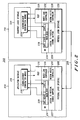
- FIG. 2 is a schematic diagram of a data transfer architecture of a communication system, according to the present invention.
- a communication system 200 such as a cellular packet data network, includes a network 202, transmitting user information to a mobile station 204 along a radio channel 206.
- network 202 is, for example, a GPRS/EDGE radio access network (GERAN).
- GERAN GPRS/EDGE radio access network
- mobile station 204 includes a physical layer unit 208 that provides interface between radio frequency hardware and a call processor (not shown), including scheduling of reception and transmission of physical data, receiver gain control, transmitter power control, signal level measurements, and so forth.
- a medium access controller 210 organizes the transmission and reception of packet-based information onto and from the physical layer interface 208, primarily including logic by which the mobile station 204 is informed of it's right to transmit at a given point. Medium access controller 210 is also responsible for the recognition of messages addressed to mobile station 204 on the downlink side.
- a radio resource controller 212 controls the mobile station 204 with regard to network-oriented signaling pertaining to the radio messages, i.e., timeslot assignments, packet data channel setups/teardowns, RF channel assignments, and so forth, in addition to passing messages originating from the network via physical layer interface 208.
- a radio link controller 214 is primarily involved with error correction at the radio layer, i.e., to absorb the periodic errors which result from the fading channel, and also handles certain aspects of GPRS/EDGE data transfer setup and teardown. In this way, radio link controller 214 maintains the integrity of the radio link through acknowledgements and re-transmissions.
- a packet data convergence protocol unit 216 packetizes/divides network protocol packet data into radio packets for transmission along radio channel 206, and provides compression and encryption services. Conversely, packet data convergence protocol unit 216 unpacketizes/divides radio packets received by mobile station 204 to the network protocol packet data for transfer to an application interface 218 of mobile station 204. Application interface 218 transfers the network protocol data from packet data convergence protocol unit 216 to a corresponding application within mobile station 204.
- a special service access point identifier (SAPI) is defined to identify each of the different non-user data message transfers to allow the multiplexing of those transfers.
- SAPI special service access point identifier
- network protocol packets corresponding to user data transmissions from network 202 to mobile station 204 are transferred by a transport layer interface 224 of network 202 to a packet data convergence protocol unit 226 which packetizes/divides the network protocol packets into radio packets.
- Network protocol packets are network packets containing network information and which utilize a network protocol, such as the known Transmission Control Protocol (TCP).
- TCP Transmission Control Protocol
- An acknowledgement coordination module 225 transmits an acknowledgement exchange message with the network protocol packets, as will be described below, indicating the mode for exchange of acknowledgment information.
- network 202 indicates either a temporary block flow acknowledgement interchange, or a main DCCH interchange as the mode for exchange of acknowledgement information.
- acknowledgement coordination module 225 determines whether acknowledgement coordination module 225 is capable of communicating with network 202 for exchange of acknowledgement information.
- acknowledgement coordination module 225 is shown in FIG. 2 as being located within transport interface layer 224, it is understood that, according to the present invention, acknowledgement coordination module 225 is not limited to being positioned within transfer layer interface 224, but may be located at other locations within network 202.
- a medium access controller 228 recognizes messages addressed to mobile station 204, and organizes transfer of the radio protocol packets onto a physical layer interface 230 for transmission along radio channel 206 to mobile station 204. Once the radio packets are received by physical layer interface 208 of mobile station 204, medium access controller 210 recognizes the radio packets as user data and transmits the radio packets to radio link controller 214, which assembles a packet data control frame including an indication of data blocks received. Packet data convergence protocol unit 216 converts the radio packets to the network protocol packets and transfers the network protocol packets to application interface 218.
- the acknowledgement exchange message from network 202 is recognized by an acknowledgment coordination module 219 of mobile station 204, and based on this acknowledgement exchange message, mobile station 204 transmits an acknowledgement of receipt of the network protocol packet to network 202 using the mode indicated in the acknowledgement exchange message, as will be described below.
- acknowledgement coordination module 225 if the mode for exchange of acknowledgement information indicated by acknowledgement coordination module 225 is determined by acknowledgement coordination module 219 to be the utilization of a temporary block flow acknowledgement interchange, mobile station 204 transfers network protocol packets containing the acknowledgment information, including the indication of data blocks received, to packet data convergence protocol unit 216. Packet data convergence protocol unit 216 packetizes/divides the network protocol packets to corresponding radio protocol packets. Medium access controller 210 then organizes the transmission of the radio protocol packets onto physical layer interface 208 for transmission along radio channel 206 to network 202.
- acknowledgement coordination module 219 is shown in FIG. 2 as being positioned within application interface 218, it is understood that, according to the present invention, acknowledgement coordination module 219 is not limited to being positioned within application interface 218, but may be located at other locations within mobile station 204.
- medium access controller 228 of network 202 recognizes the radio protocol packets as user data and transfers the radio protocol packets to a radio link controller 232.
- Radio link controller 232 recognizes which data blocks from the original transmission, if any, were indicated as not being received by radio link controller 214 of mobile station 204, and packet data convergence protocol unit 226 converts the radio protocol packets to network protocol packets, which are transferred to transport layer interface 224.
- data blocks are indicated as not being received by mobile station 204, those data blocks are re-transferred along radio channel 206 from network 202 to mobile station 204 through packet data convergence protocol units 226 and 216, radio link controllers 232 and 214, medium access controllers 228 and 210 and physical layer interfaces 230 and 208 in the same way as described above.
- acknowledgement coordination module 225 of network 202 is a dedicated control channel acknowledgement interchange
- mobile station 204 transfers the acknowledgement information, including the indication of data blocks received, to network 202 along a main dedicated control channel 220 of radio resource controller 212.
- acknowledgement coordination module 225 of network 202 is a dedicated control channel acknowledgement interchange
- acknowledgement coordination module 219 determines that the mode indicated in the network protocol packet from packet data convergence protocol unit 216 is the main dedicated control channel
- application interface 218 transfers the acknowledgement information, including the indication of the data blocks received, to a defined service access point identifier of service access point identifiers SAPI0 to SAPI n that corresponds to acknowledgement information, enabling transmission of the acknowledgement information through main dedicated control channel 220 of radio resource controller 212.
- Logical to physical mapping unit 222 maps the transmission from main dedicated control channel 220 to physical layer interface 208, and medium access controller 210 controls the transfer of the acknowledgement information from main dedicated control channel 220 to physical layer interface 208 for transmission along to radio channel 206.
- medium access controller 228 recognizes the acknowledgement information as control information, and maps the acknowledgement information to a main dedicated control channel 238 of a radio resource controller 234 through a logical to physical channel mapping unit 236 of network 202 that maps acknowledgement information according to the defined service access point indicator.
- the acknowledgement information is then transmitted to transport layer interface 224 via the defined service access point identifier.
- data blocks are indicated as not being received by mobile station 204, those data blocks are re-transferred along radio channel from network 202 to mobile station 204 through packet data convergence protocol units 226 and 216, radio link controllers 232 and 214, medium access controllers 228 and 210 and physical layer interfaces 230 and 208 in the same way as described above.
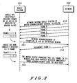
- FIG. 3 is a data flow diagram of acknowledgement message interchange between a network 202 and a mobile station 204, according to the present invention.
- the indication from acknowledgement coordination module 225 as to the desired mode for interchange of acknowledgement information is transmitted from network 202 to mobile station 204 in an acknowledgement exchange message 240.
- acknowledgement exchange message 240 informs mobile station 204 to utilized either a temporary block flow or a main dedicated control channel for exchange of acknowledgement information.
- acknowledgement exchange message 240 is included in a request for acknowledgement information transmitted from network 202 to mobile station 204.
- acknowledgement exchange message 240 is included in the packet downlink assignment message of the known temporary block flow setup for transmission from network to mobile station 204.
- acknowledgement exchange message 240 containing the indication of the mode for exchange of acknowledgement information interchange is transmitted along radio channel 206 from network 202 to mobile station 204 through a service access point identifier from service point identifiers SAPI 0 - SAPI n, main dedicated control channels 238 and 220, logical to physical channel mapping units 236 and 222, medium access controllers 228 and 210, and physical layer interfaces 230 and 208, and is received by acknowledgement coordination module 219 of application interface 218.
- acknowledgement coordination module 219 determines that the desired mode indicated by acknowledgement exchange message 240 is the temporary block flow, or if no desired mode for exchange of acknowledgement information is indicated, acknowledgement information is transmitted from mobile station 204 to network 202 through packet data convergence protocol units 216 and 226, radio link controllers 214 and 232, medium access controllers 210 and 228, and physical layer interfaces 208 and 230, using the known temporary block flow setup for acknowledgement transmission by mobile station 204.
- acknowledgement coordination module 219 determines that the desired mode indicated by acknowledgement exchange message 240 is the main dedicated control channel
- acknowledgement information is transmitted in an acknowledgement message 242 from mobile station 204 to network 202 through a defined service access point identifier of SAPI 0-SAPI 1 defined for acknowledgement exchange, main dedicated control channels 238 and 220, logical to physical channel mapping units 236 and 222, medium access controllers 228 and 210, and physical layer interfaces 230 and 208.
- acknowledgement message 242 indicates that frames zero, one and three were successfully received.
- Network 202 responds to acknowledgement message 242 by re-transmitting data frames 244, if any, that were not received by mobile station 204 until an acknowledgement message 246 indicating receipt of all frames has been received from mobile station 204.
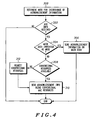
- FIG. 4 is a flowchart of interchange of an acknowledgement message between a network and a user application, according to the present invention.
- network 100 initially determines whether to utilize the conventional temporary block flow or the main dedicated control channel as the mode for interchange of acknowledgement information, and transmits the determined mode to mobile station 204 in Step 300.
- acknowledgement coordination module 219 of mobile station 104 determines that acknowledgement information has been received, Step 302
- a determination is made as to whether the main dedicated control channel is the mode indicated for interchange of acknowledgement information, Step 304. If the main dedicated control channel is the mode indicated for interchange of acknowledgement information, mobile station 204 sends acknowledgement information, including an indication of frames received, on main dedicated control channel 220 using the defined special SAPI, Step 306.
- Step 308 a determination is made as to whether conventional resources, i.e., for a temporary block flow setup, are available, Step 308. If conventional resources are available, the acknowledgement information is transmitted by mobile station 204 using conventional medium access resources, Step 310. If conventional resources are not available, mobile station 204 requests the conventional resources, Step 312, and the acknowledgement information is then transmitted by mobile station using conventional medium access resources, Step 310.
- conventional resources i.e., for a temporary block flow setup
Landscapes
- Engineering & Computer Science (AREA)
- Computer Networks & Wireless Communication (AREA)
- Signal Processing (AREA)
- Mobile Radio Communication Systems (AREA)
Description
- The present invention relates generally to cellular packet data networks, and in particular, the present invention relates to a method and apparatus for exchanging acknowledgement information between a mobile station and a network in a cellular packet data network.
- The Global System for Mobile Communications (GSM) General Packet Radio Service (GPRS) and Enhanced Data for Global Evolution (EDGE) is intended to enable a service subscriber to send and receive data in an end-to-end packet transfer mode without utilization of network resources in the circuit-switched mode. GPRS, EDGE and 3rd Generation (3G) packet radio services permit the efficient use of radio and network resources when data transmission characteristics are i) packet based, ii) intermittent and non-periodic, iii) possibly frequent, with small transfers of data, e.g. less than 500 octets, or iv) possibly infrequent, with large transfers of data, e.g. more than several hundred kilobytes. User applications may include Internet browsers, electronic mail, and so on. GPRS/EDGE radio access network (GERAN) is the real-time migration path for GPRS/EDGE into 3rd generation wireless.
- It is generally assumed that most internet application data traffic is generally biased in the downlink direction, meaning that a majority of application data traffic is transmitted from the network to a user application. This assumption is based both on the expected behavior of the user, since most users engage in applications that require the reception of much larger amounts of information from the network relative to the amount of information required to be transmitted to the network, and on the inherent properties of many of the applications themselves. For example, accessing a page of information on the worldwide web (WWW) requires a very short transmission of an address sequence on the uplink, i.e., from the user application to the network, followed by the reception of data on the downlink, i.e., from the network to the user application, which may be several orders of magnitude larger than the transmission that caused the downlink transfer. Therefore, known packet-based systems have been constructed to support a greater flow of information in the downlink direction, and to segregate the allocation of uplink and downlink resources from one another. This construction of packet-based systems differs, for example, from the construction of circuit-switched methods, which tend to be constructed as a bi-directional virtual circuit allocating dedicated resources which may be used only occasionally throughout the life of the session.
-
FIG. 1 (Prior Art) is a flow diagram of unidirectional information flow over a radio channel from a network to a user application. In spite of the fact that downlink internet data appears to flow in a single direction much of the time, there is the additional requirement to maintain the integrity of the information as it crosses the radio fading channel in a wireless domain. One of the primary known mechanisms for protecting data integrity over the fading channel involves the concept of acknowledged network protocols. For example, in a GSM/3G radio environment in which a unidirectional packet data transfer is required, it is almost always the case, unless the transfer involves embedded voice or video, that network level acknowledgements from the user application are required in order to preserve the integrity of information across the fading channel in the presence of deep fades. - As illustrated in
FIG.1 , anetwork 100 begins a setup sequence in a downlink setup period by sending apacket paging request 102 along a radio channel to amobile station 104. Once arandom access burst 106 is received frommobile station 104,network 100 sends animmediate assignment message 108 and a packetdownlink assignment message 110, detailing the parameters of the assignment, such as over what channel the transfer would take place, when the transfer would start, and so forth. Prior to transmission bynetwork 100, the information intended to be transferred tomobile station 104 is divided into packets, so that after receiving a packet control acknowledgemessage 112 frommobile station 104 indicating acknowledgement bymobile station 104 of the parameters of the assignment detailed inimmediate assignment message 108 and packetdownlink assignment message 110,network 100 sends a series of data blocks, orframes 114, containing the packets tomobile station 104. - Upon receiving
frames 114,mobile station 104 sets up atemporary block flow 116 to transmit an acknowledgement message to thenetwork 100. As illustrated inFIG. 1 , during setup oftemporary block flow 116,mobile station 104 transmits a channelrequest access burst 118 tonetwork 100, which responds by transmitting animmediate assignment message 120.Mobile station 104 then transmits a packetresource request message 122 tonetwork 100 requesting resources for the temporary block flow.Network 100 responds by transmitting a packetuplink assignment message 124 tomobile station 104, andmobile station 104 acknowledges receipt of packetuplink assignment message 124 by transmitting a packetcontrol acknowledgement message 126 tonetwork 100. - Once packet
control acknowledgement message 126 has been transmitted,mobile station 104 transmits anacknowledgement message 128 that indicates which frames offrames 114 were received bymobile station 104, along with a request for re-transmission of the frames that were not received. For example, as illustrated inFIG. 1 , as a result of the radio fading channel,mobile station 104 may have only received frame zero and frame three of frame zero through frame three that were sent fromnetwork 100. Therefore,network acknowledgement message 128 would indicate that frame zero and frame three where received, and would request re-transmission of frame one and frame two. Frame one and frame two would then be re-transmitted bynetwork 100 tomobile station 104, which, assuming no effects from the radio fading channel, are subsequently received bymobile station 104. Ifnetwork 100 is in a ready state upon receivingnetwork acknowledgement message 128, the setup for re-transmission would not be required. However, ifnetwork 100 is not in a ready state, the setup would have to be repeated, requiring the use of even more resources. - Upon receiving frame one and frame two,
mobile station 104 again sets up atemporary block flow 130 to transmit anacknowledgement message 132 to thenetwork 100 by sending a channelrequest access burst 134 tonetwork 100, which responds by sending animmediate assignment message 136.Mobile station 104 then sends a packetresource request message 138 tonetwork 100 requesting resources for the temporary block flow.Network 100 responds by sending a packetuplink assignment message 140 tomobile station 104, andmobile station 104 acknowledges receipt of packetuplink assignment message 140 by sending network 100 a packetcontrol acknowledgement message 142. Once packetcontrol acknowledgement message 142 has been sent,mobile station 104 transmitsnetwork acknowledgement message 132 containing an indication that frame one and frame two were received. - The use of such network acknowledgements is problematic in that within current specifications for GPRS/EDGE and 3G packet data services, the setup of the logical channel over which radio link acknowledgments are sent requires a substantial amount of time and coordination by the network. Furthermore, the allocation of radio resources for such radio-level acknowledgments generally impacts the system capacity, and there may be cases when there are radio resources in one direction but not in the other direction for a full allocation, causing radio link control timers to expire and a flurry of unnecessary re-transmission queries to be made.
- Accordingly, what is needed is an improved method and apparatus for exchanging acknowledgement information between a user application and a network.
- An article entitled 'Wireless Internet Access Based on GPRS', by Roger Kalden et al., IEEE Personal Communications, IEEE Communications Society, US, Vol. 7, no.2, April 2000, pages 8-18 describes the performance the end user perceives when retrieving information from the Internet using GPRS.
-
US patent no. 6,064,889 describes a system for directing dual-mode mobile stations from an analog control channel (ACCH) to a digital control channel (DCCH). The selection is based on the subscriber profile and current location of the dual-mode mobile station. - The invention is described in the appended
claims 1, 8, and 13. Further embodiments can be found in the dependent claims. - The features of the present invention which are believed to be novel are set forth with particularity in the appended claims. The invention, together with further objects and advantages thereof, may best be understood by making reference to the following description, taken in conjunction with the accompanying drawings, in the several figures of which like reference numerals identify like elements, and wherein:
-
FIG. 1 (Prior Art) is a flow diagram of unidirectional information flow over a radio channel from a network to a user application. -
FIG. 2 is a schematic diagram of a data transfer architecture of a communication system, according to the present invention. -
FIG. 3 is a data flow diagram of acknowledgement message interchange between a network and a mobile station, according to the present invention. -
FIG. 4 is a flowchart of interchange of an acknowledgement message between a network and a user application, according to the present invention. - The present invention makes use of the GSM and 3G concept of a "main dedicated control channel" (DCCH), over which signaling information is sent. The main DCCH may comprise different underlying basic physical channels depending upon in what mode the mobile station operates at a given point in time, and is viewed as a "logical virtual circuit". According to the present invention, the main DCCH is utilized for the exchange of radio link acknowledgment information in the opposite direction when i) a unidirectional data transfer is performed and ii) the conventional radio resources in the opposite direction are unavailable. Acknowledgment information arriving at an acknowledgment coordination module would be transported either over the main DCCH via a special service access point identifier (SAPI) or over the conventional medium access control (MAC) mechanism. The determination of which mode to utilize is made by the network, by transmitting an indication of the mode. Such a transmission is made, for example, in the request for acknowledgment information, which is transmitted from the network to the mobile station. This indication is necessary, because under normal conditions, the mobile station is not allowed to utilize the main DCCH for transmission using the special SAPI, unless the network has granted such usage. Furthermore, the network may not be equipped to utilize the special SAPI for such acknowledgments.
- The request for acknowledgment contains an indication of the mode for exchange of acknowledgment information, as well as the standard information requesting an acknowledgment. If the request does not indicate a mode, the request is interpreted by the receiving entity as a request for the standard acknowledgment means using conventional resources.
-
FIG. 2 is a schematic diagram of a data transfer architecture of a communication system, according to the present invention. As illustrated inFIG. 2 , acommunication system 200, such as a cellular packet data network, includes anetwork 202, transmitting user information to amobile station 204 along aradio channel 206. In particular, according to the present invention,network 202 is, for example, a GPRS/EDGE radio access network (GERAN). - According to the present invention,
mobile station 204 includes aphysical layer unit 208 that provides interface between radio frequency hardware and a call processor (not shown), including scheduling of reception and transmission of physical data, receiver gain control, transmitter power control, signal level measurements, and so forth. Amedium access controller 210 organizes the transmission and reception of packet-based information onto and from thephysical layer interface 208, primarily including logic by which themobile station 204 is informed of it's right to transmit at a given point.Medium access controller 210 is also responsible for the recognition of messages addressed tomobile station 204 on the downlink side. - A
radio resource controller 212 controls themobile station 204 with regard to network-oriented signaling pertaining to the radio messages, i.e., timeslot assignments, packet data channel setups/teardowns, RF channel assignments, and so forth, in addition to passing messages originating from the network viaphysical layer interface 208. Aradio link controller 214 is primarily involved with error correction at the radio layer, i.e., to absorb the periodic errors which result from the fading channel, and also handles certain aspects of GPRS/EDGE data transfer setup and teardown. In this way,radio link controller 214 maintains the integrity of the radio link through acknowledgements and re-transmissions. - A packet data
convergence protocol unit 216 packetizes/divides network protocol packet data into radio packets for transmission alongradio channel 206, and provides compression and encryption services. Conversely, packet dataconvergence protocol unit 216 unpacketizes/divides radio packets received bymobile station 204 to the network protocol packet data for transfer to anapplication interface 218 ofmobile station 204.Application interface 218 transfers the network protocol data from packet dataconvergence protocol unit 216 to a corresponding application withinmobile station 204. - In this way, user or traffic data is transferred between
application interface 218 andphysical layer interface 208 through packet dataconvergence protocol unit 216,radio link controller 214,radio resource controller 212, andmedium access controller 210. On the other hand, message transfers betweennetwork 202 andmobile station 204 that involve transfer of data other than user data, such as transfer of control data during call setup betweennetwork 202 andmobile station 204, are transmitted using a main dedicatedcontrol channel controller 220. A special service access point identifier (SAPI) is defined to identify each of the different non-user data message transfers to allow the multiplexing of those transfers. A logical to physicalchannel mapping controller 222 links the non-traffic messages betweenphysical layer interface 208 and main dedicatedcontrol channel controller 220. - According to the present invention, network protocol packets corresponding to user data transmissions from
network 202 tomobile station 204 are transferred by atransport layer interface 224 ofnetwork 202 to a packet dataconvergence protocol unit 226 which packetizes/divides the network protocol packets into radio packets. Network protocol packets are network packets containing network information and which utilize a network protocol, such as the known Transmission Control Protocol (TCP). - An
acknowledgement coordination module 225 transmits an acknowledgement exchange message with the network protocol packets, as will be described below, indicating the mode for exchange of acknowledgment information. For example, according to the present invention,network 202 indicates either a temporary block flow acknowledgement interchange, or a main DCCH interchange as the mode for exchange of acknowledgement information. - According to the present invention, the determination by
acknowledgement coordination module 225 of which mode is to be indicated bynetwork 202 for exchange of acknowledgement information can be determined by any number of factors, such as radio resource availability and network congestion, for example. In addition, whileacknowledgement coordination module 225 is shown inFIG. 2 as being located withintransport interface layer 224, it is understood that, according to the present invention,acknowledgement coordination module 225 is not limited to being positioned withintransfer layer interface 224, but may be located at other locations withinnetwork 202. - A medium access controller 228 recognizes messages addressed to
mobile station 204, and organizes transfer of the radio protocol packets onto aphysical layer interface 230 for transmission alongradio channel 206 tomobile station 204. Once the radio packets are received byphysical layer interface 208 ofmobile station 204,medium access controller 210 recognizes the radio packets as user data and transmits the radio packets toradio link controller 214, which assembles a packet data control frame including an indication of data blocks received. Packet dataconvergence protocol unit 216 converts the radio packets to the network protocol packets and transfers the network protocol packets toapplication interface 218. The acknowledgement exchange message fromnetwork 202 is recognized by an acknowledgment coordination module 219 ofmobile station 204, and based on this acknowledgement exchange message,mobile station 204 transmits an acknowledgement of receipt of the network protocol packet to network 202 using the mode indicated in the acknowledgement exchange message, as will be described below. - For example, according to the present invention, if the mode for exchange of acknowledgement information indicated by
acknowledgement coordination module 225 is determined by acknowledgement coordination module 219 to be the utilization of a temporary block flow acknowledgement interchange,mobile station 204 transfers network protocol packets containing the acknowledgment information, including the indication of data blocks received, to packet dataconvergence protocol unit 216. Packet dataconvergence protocol unit 216 packetizes/divides the network protocol packets to corresponding radio protocol packets.Medium access controller 210 then organizes the transmission of the radio protocol packets ontophysical layer interface 208 for transmission alongradio channel 206 tonetwork 202. - While acknowledgement coordination module 219 is shown in
FIG. 2 as being positioned withinapplication interface 218, it is understood that, according to the present invention, acknowledgement coordination module 219 is not limited to being positioned withinapplication interface 218, but may be located at other locations withinmobile station 204. - Once the radio protocol packets from
mobile station 204 are received byphysical layer interface 230, medium access controller 228 ofnetwork 202 recognizes the radio protocol packets as user data and transfers the radio protocol packets to aradio link controller 232.Radio link controller 232 recognizes which data blocks from the original transmission, if any, were indicated as not being received byradio link controller 214 ofmobile station 204, and packet dataconvergence protocol unit 226 converts the radio protocol packets to network protocol packets, which are transferred to transportlayer interface 224. If data blocks are indicated as not being received bymobile station 204, those data blocks are re-transferred alongradio channel 206 fromnetwork 202 tomobile station 204 through packet dataconvergence protocol units radio link controllers medium access controllers 228 and 210 and physical layer interfaces 230 and 208 in the same way as described above. - On the other hand, according to the present invention, if the mode for exchange of acknowledgement information indicated by
acknowledgement coordination module 225 ofnetwork 202 is a dedicated control channel acknowledgement interchange,mobile station 204 transfers the acknowledgement information, including the indication of data blocks received, to network 202 along a maindedicated control channel 220 ofradio resource controller 212. In particular, as illustrated inFIG. 2 , if acknowledgement coordination module 219 determines that the mode indicated in the network protocol packet from packet dataconvergence protocol unit 216 is the main dedicated control channel,application interface 218 transfers the acknowledgement information, including the indication of the data blocks received, to a defined service access point identifier of service access point identifiers SAPI0 to SAPI n that corresponds to acknowledgement information, enabling transmission of the acknowledgement information through maindedicated control channel 220 ofradio resource controller 212. Logical tophysical mapping unit 222 maps the transmission from maindedicated control channel 220 tophysical layer interface 208, andmedium access controller 210 controls the transfer of the acknowledgement information from maindedicated control channel 220 tophysical layer interface 208 for transmission along toradio channel 206. - Once the acknowledgement information is received by
physical layer interface 230 ofnetwork 202, medium access controller 228 recognizes the acknowledgement information as control information, and maps the acknowledgement information to a maindedicated control channel 238 of aradio resource controller 234 through a logical to physicalchannel mapping unit 236 ofnetwork 202 that maps acknowledgement information according to the defined service access point indicator. The acknowledgement information is then transmitted to transportlayer interface 224 via the defined service access point identifier. If data blocks are indicated as not being received bymobile station 204, those data blocks are re-transferred along radio channel fromnetwork 202 tomobile station 204 through packet dataconvergence protocol units radio link controllers medium access controllers 228 and 210 and physical layer interfaces 230 and 208 in the same way as described above. -
FIG. 3 is a data flow diagram of acknowledgement message interchange between anetwork 202 and amobile station 204, according to the present invention. According to the present invention, as illustrated inFIG. 3 , the indication fromacknowledgement coordination module 225 as to the desired mode for interchange of acknowledgement information is transmitted fromnetwork 202 tomobile station 204 in anacknowledgement exchange message 240. According to the present invention,acknowledgement exchange message 240 informsmobile station 204 to utilized either a temporary block flow or a main dedicated control channel for exchange of acknowledgement information. - In a preferred embodiment of the present invention,
acknowledgement exchange message 240 is included in a request for acknowledgement information transmitted fromnetwork 202 tomobile station 204. For example, according to the present invention,acknowledgement exchange message 240 is included in the packet downlink assignment message of the known temporary block flow setup for transmission from network tomobile station 204. In this way, according to the present invention,acknowledgement exchange message 240 containing the indication of the mode for exchange of acknowledgement information interchange is transmitted alongradio channel 206 fromnetwork 202 tomobile station 204 through a service access point identifier from service point identifiers SAPI 0 - SAPI n, maindedicated control channels channel mapping units medium access controllers 228 and 210, and physical layer interfaces 230 and 208, and is received by acknowledgement coordination module 219 ofapplication interface 218. - According to the present invention, if the acknowledgement coordination module 219 determines that the desired mode indicated by
acknowledgement exchange message 240 is the temporary block flow, or if no desired mode for exchange of acknowledgement information is indicated, acknowledgement information is transmitted frommobile station 204 to network 202 through packet dataconvergence protocol units radio link controllers medium access controllers 210 and 228, and physical layer interfaces 208 and 230, using the known temporary block flow setup for acknowledgement transmission bymobile station 204. - However, as illustrated in
FIGS. 2 and3 , if acknowledgement coordination module 219 determines that the desired mode indicated byacknowledgement exchange message 240 is the main dedicated control channel, acknowledgement information is transmitted in anacknowledgement message 242 frommobile station 204 to network 202 through a defined service access point identifier of SAPI 0-SAPI 1 defined for acknowledgement exchange, maindedicated control channels channel mapping units medium access controllers 228 and 210, and physical layer interfaces 230 and 208. For example, as illustrated inFIG. 3 ,acknowledgement message 242 indicates that frames zero, one and three were successfully received.Network 202 responds toacknowledgement message 242 by re-transmittingdata frames 244, if any, that were not received bymobile station 204 until anacknowledgement message 246 indicating receipt of all frames has been received frommobile station 204. -
FIG. 4 is a flowchart of interchange of an acknowledgement message between a network and a user application, according to the present invention. As illustrated inFIGS. 2 and4 ,network 100 initially determines whether to utilize the conventional temporary block flow or the main dedicated control channel as the mode for interchange of acknowledgement information, and transmits the determined mode tomobile station 204 inStep 300. When acknowledgement coordination module 219 ofmobile station 104 determines that acknowledgement information has been received,Step 302, a determination is made as to whether the main dedicated control channel is the mode indicated for interchange of acknowledgement information,Step 304. If the main dedicated control channel is the mode indicated for interchange of acknowledgement information,mobile station 204 sends acknowledgement information, including an indication of frames received, on maindedicated control channel 220 using the defined special SAPI,Step 306. However, if the main dedicated control channel is not the mode indicated for interchange of acknowledgement information, a determination is made as to whether conventional resources, i.e., for a temporary block flow setup, are available,Step 308. If conventional resources are available, the acknowledgement information is transmitted bymobile station 204 using conventional medium access resources,Step 310. If conventional resources are not available,mobile station 204 requests the conventional resources,Step 312, and the acknowledgement information is then transmitted by mobile station using conventional medium access resources,Step 310. - While a particular embodiment of the present invention has been shown and described, modifications may be made. For example, although four frames are shown in
FIG. 3 for purposes of simplification of the description, it is understood that actual implementations are likely to have window sizes much larger than four frames. It is therefore intended in the appended claims to cover all such changes and modifications that fall within the scope of the invention as defined in the appended claims.
Claims (15)
- A communication system (200), including a mobile station (204) for transmitting acknowledgement information to a network (202), the communication system being
characterised by:a first acknowledgement coordination module (225), positioned within the network (202), for transmitting an acknowledgement exchange message (240) to the mobile station (204) indicating a mode for exchange of the acknowledgement information; anda second acknowledgement coordination module (219), positioned within the mobile station (204), for transmitting the acknowledgement information to the network (202) using the indicated mode,wherein the mobile station (204) is arranged to transmit acknowledgement information along a main dedicated control channel (220) in response to the indicated mode being the main dedicated control channel,wherein the mobile station (204) is arranged to transmit the acknowledgement information to the network (202) using a temporary block flow acknowledgement interchange in response to the indicated mode being other than the main dedicated control channel or the indicated mode not being received, andwherein the main dedicated control channel (220) includes a defined service access point identifier corresponding to the acknowledgement information for transmission of the acknowledgement information through the main dedicated control channel (220). - The communication system (200) of claim 1, wherein the network,(202) is arranged to determine the mode for exchange of the acknowledgement information based on resource availability of the network.
- The communication system (200) of claim 1, wherein the network (202) is arranged to determine the mode for exchange of the acknowledgement information based on resource availability of the network and network congestion.
- The communication system (200) of any preceding claim, wherein the mobile station (204) includes an application interface (218) for transferring network protocol information to a corresponding application within the mobile station (204), and wherein the second acknowledgement coordination module (219) is positioned within the application interface (218).
- The communication system (200) of claim 4, wherein the network includes a transport layer interface (224) for transferring the network protocol information to the mobile station, and wherein the first acknowledgement coordination module (225) is positioned within the transport layer interface (224).
- The communication system (200) of any preceding claim, wherein the network (202) is arranged to transmit a request for acknowledgement information to the mobile station and wherein the acknowledgement exchange message (240) is included in the request for acknowledgement information.
- The communication system (200) of claim 6, wherein the acknowledgement exchange message (240) is included in a packet downlink assignment message of a temporary block flow setup corresponding to the request for acknowledgement information transmitted from the network (202) to the mobile station (204).
- A mobile station (204) for receiving network information transmitted from a network (202) along a radio channel (206), the mobile station (204) comprising:an acknowledgement coordination module (219) for determining a mode for exchange of acknowledgement information with the network (202) based on a received acknowledgement exchange message (240) the received acknowledgement exchange message (240) indicating a mode for exchange of acknowledgement information ; andwherein the mobile station (204) is arranged to transmit acknowledgement information to the network (202) through a main dedicated control channel (220) in response to the indicated mode for exchange of acknowledgement information being the main dedicated control channel (220)wherein the mobile station (204) is arranged to transmit acknowledgement information to the network (202) using a temporary block flow acknowledgement interchange in response to the indicated mode being other than the main dedicated control channel or the determined mode not being received, andwherein the main dedicated control channel (220) includes a defined service access point identifier corresponding to the acknowledgement information for transmission of the acknowledgement information through the main dedicated control channel (220)
- The mobile station (204) of claim 8, wherein the network (202) is arranged to determine the mode for exchange of the acknowledgement information based on resource availability of the network.
- The mobile station (204) of claim 8, wherein the network (202) is arranged to determine the mode for exchange of the acknowledgement information based on resource availability of the network (202) and network congestion.
- The mobile station (204) of claim 8, 9 or 10, further comprising an application interface (218) for transferring network information from the network (202) to a corresponding application within the mobile station (204), wherein the acknowledgement coordination module (219) is positioned within the application interface (218).
- The mobile station (204) of claim 8, 9, 10 or 11, wherein the network (202) is a GPRS/EDGE radio access network.
- A method for exchange of acknowledgement information between a network (202) and a mobile station (204), the method being characterized by:receiving (304) at the mobile station (204) an acknowledgement exchange message (240), the acknowledgement exchange message indicating a mode for an exchange of acknowledgement information; andtransmitting (306) acknowledgement information to the network (202) along a main dedicated control channel (220) in response to the indicated mode being the main dedicated control channel; andtransmitting (310) acknowledgement information to the network (202) using a temporary block flow acknowledgement interchange in response to the indicated mode being other than the main dedicated control channel or the indicated mode not being received,wherein the main dedicated control channel (220) includes a defined service access point identifier corresponding to the acknowledgement information for transmission of the acknowledgement information through the main dedicated control channel (220).
- The method of claim 13, further comprising determining the mode for the exchange of the acknowledgement information based on radio resource availability of the network.
- The method of claim 13, further comprising determining the mode for the exchange of the acknowledgement information based on radio resource availability and network congestion.
Applications Claiming Priority (3)
| Application Number | Priority Date | Filing Date | Title |
|---|---|---|---|
| US649105 | 2000-08-25 | ||
| US09/649,105 US6487184B1 (en) | 2000-08-25 | 2000-08-25 | Method and apparatus for supporting radio acknowledgement information for a uni-directional user data channel |
| PCT/US2001/026228 WO2002019746A1 (en) | 2000-08-25 | 2001-08-22 | Method and apparatus for supporting radio acknowledgement information for a uni-directional user data channel |
Publications (3)
| Publication Number | Publication Date |
|---|---|
| EP1314328A1 EP1314328A1 (en) | 2003-05-28 |
| EP1314328A4 EP1314328A4 (en) | 2007-08-29 |
| EP1314328B1 true EP1314328B1 (en) | 2013-06-26 |
Family
ID=24603483
Family Applications (1)
| Application Number | Title | Priority Date | Filing Date |
|---|---|---|---|
| EP01964333.7A Expired - Lifetime EP1314328B1 (en) | 2000-08-25 | 2001-08-22 | Method and apparatus for supporting radio acknowledgement information for a uni-directional user data channel |
Country Status (13)
| Country | Link |
|---|---|
| US (1) | US6487184B1 (en) |
| EP (1) | EP1314328B1 (en) |
| JP (1) | JP2004507950A (en) |
| KR (1) | KR100546529B1 (en) |
| CN (1) | CN1218590C (en) |
| AU (2) | AU8519801A (en) |
| BR (1) | BR0113514B1 (en) |
| CA (1) | CA2421071C (en) |
| HU (1) | HUP0303057A2 (en) |
| MX (1) | MXPA03001639A (en) |
| RU (1) | RU2256299C2 (en) |
| WO (1) | WO2002019746A1 (en) |
| ZA (1) | ZA200301174B (en) |
Families Citing this family (79)
| Publication number | Priority date | Publication date | Assignee | Title |
|---|---|---|---|---|
| US6360100B1 (en) | 1998-09-22 | 2002-03-19 | Qualcomm Incorporated | Method for robust handoff in wireless communication system |
| US7068623B1 (en) | 2000-01-10 | 2006-06-27 | Nortel Networks Limited | Communicating traffic over a wireless channel in a mobile communications system |
| US7586949B1 (en) | 2000-04-03 | 2009-09-08 | Nortel Networks Limited | Interleaving data over frames communicated in a wireless channel |
| US9130810B2 (en) | 2000-09-13 | 2015-09-08 | Qualcomm Incorporated | OFDM communications methods and apparatus |
| US7295509B2 (en) | 2000-09-13 | 2007-11-13 | Qualcomm, Incorporated | Signaling method in an OFDM multiple access system |
| US6967964B1 (en) * | 2000-10-03 | 2005-11-22 | Telefonaktiebolaget Lm Ericsson (Publ) | Context identification using header compression key at link layer |
| US6701151B2 (en) * | 2001-03-27 | 2004-03-02 | Ericsson Inc. | Short access for realizing a signaling radio bearer in geran |
| US7165112B2 (en) * | 2001-06-22 | 2007-01-16 | Motorola, Inc. | Method and apparatus for transmitting data in a communication system |
| US7672274B2 (en) | 2002-01-11 | 2010-03-02 | Broadcom Corporation | Mobility support via routing |
| US7689210B1 (en) * | 2002-01-11 | 2010-03-30 | Broadcom Corporation | Plug-n-playable wireless communication system |
| US7149196B1 (en) | 2002-01-11 | 2006-12-12 | Broadcom Corporation | Location tracking in a wireless communication system using power levels of packets received by repeaters |
| US8027637B1 (en) | 2002-01-11 | 2011-09-27 | Broadcom Corporation | Single frequency wireless communication system |
| US7515557B1 (en) | 2002-01-11 | 2009-04-07 | Broadcom Corporation | Reconfiguration of a communication system |
| US7876704B1 (en) | 2002-01-11 | 2011-01-25 | Broadcom Corporation | Tunneling protocols for wireless communications |
| US7113498B2 (en) * | 2002-06-05 | 2006-09-26 | Broadcom Corporation | Virtual switch |
| US7668541B2 (en) | 2003-01-31 | 2010-02-23 | Qualcomm Incorporated | Enhanced techniques for using core based nodes for state transfer |
| DE10320670A1 (en) * | 2003-05-08 | 2004-12-30 | Rohde & Schwarz Gmbh & Co. Kg | Method and tester for determining an error rate of a mobile radio device, in particular for USF-BLER |
| US9148256B2 (en) | 2004-07-21 | 2015-09-29 | Qualcomm Incorporated | Performance based rank prediction for MIMO design |
| US9137822B2 (en) | 2004-07-21 | 2015-09-15 | Qualcomm Incorporated | Efficient signaling over access channel |
| US9246560B2 (en) | 2005-03-10 | 2016-01-26 | Qualcomm Incorporated | Systems and methods for beamforming and rate control in a multi-input multi-output communication systems |
| US9154211B2 (en) | 2005-03-11 | 2015-10-06 | Qualcomm Incorporated | Systems and methods for beamforming feedback in multi antenna communication systems |
| US8446892B2 (en) | 2005-03-16 | 2013-05-21 | Qualcomm Incorporated | Channel structures for a quasi-orthogonal multiple-access communication system |
| US9520972B2 (en) | 2005-03-17 | 2016-12-13 | Qualcomm Incorporated | Pilot signal transmission for an orthogonal frequency division wireless communication system |
| US9461859B2 (en) | 2005-03-17 | 2016-10-04 | Qualcomm Incorporated | Pilot signal transmission for an orthogonal frequency division wireless communication system |
| US9143305B2 (en) | 2005-03-17 | 2015-09-22 | Qualcomm Incorporated | Pilot signal transmission for an orthogonal frequency division wireless communication system |
| US9184870B2 (en) | 2005-04-01 | 2015-11-10 | Qualcomm Incorporated | Systems and methods for control channel signaling |
| US9036538B2 (en) | 2005-04-19 | 2015-05-19 | Qualcomm Incorporated | Frequency hopping design for single carrier FDMA systems |
| US9408220B2 (en) | 2005-04-19 | 2016-08-02 | Qualcomm Incorporated | Channel quality reporting for adaptive sectorization |
| EP1884079B1 (en) * | 2005-05-24 | 2018-10-24 | Telecom Italia S.p.A. | Method and apparatuses for dimensioning a data packets handler apparatus in a packet-switched mobile communications network |
| US8565194B2 (en) | 2005-10-27 | 2013-10-22 | Qualcomm Incorporated | Puncturing signaling channel for a wireless communication system |
| US8879511B2 (en) | 2005-10-27 | 2014-11-04 | Qualcomm Incorporated | Assignment acknowledgement for a wireless communication system |
| US8611284B2 (en) | 2005-05-31 | 2013-12-17 | Qualcomm Incorporated | Use of supplemental assignments to decrement resources |
| US8462859B2 (en) | 2005-06-01 | 2013-06-11 | Qualcomm Incorporated | Sphere decoding apparatus |
| US9179319B2 (en) | 2005-06-16 | 2015-11-03 | Qualcomm Incorporated | Adaptive sectorization in cellular systems |
| US8599945B2 (en) | 2005-06-16 | 2013-12-03 | Qualcomm Incorporated | Robust rank prediction for a MIMO system |
| US8885628B2 (en) | 2005-08-08 | 2014-11-11 | Qualcomm Incorporated | Code division multiplexing in a single-carrier frequency division multiple access system |
| US20070041457A1 (en) | 2005-08-22 | 2007-02-22 | Tamer Kadous | Method and apparatus for providing antenna diversity in a wireless communication system |
| US9209956B2 (en) | 2005-08-22 | 2015-12-08 | Qualcomm Incorporated | Segment sensitive scheduling |
| US8644292B2 (en) | 2005-08-24 | 2014-02-04 | Qualcomm Incorporated | Varied transmission time intervals for wireless communication system |
| US9136974B2 (en) | 2005-08-30 | 2015-09-15 | Qualcomm Incorporated | Precoding and SDMA support |
| US8509799B2 (en) | 2005-09-19 | 2013-08-13 | Qualcomm Incorporated | Provision of QoS treatment based upon multiple requests |
| US9736752B2 (en) | 2005-12-22 | 2017-08-15 | Qualcomm Incorporated | Communications methods and apparatus using physical attachment point identifiers which support dual communications links |
| US8982778B2 (en) | 2005-09-19 | 2015-03-17 | Qualcomm Incorporated | Packet routing in a wireless communications environment |
| US9078084B2 (en) | 2005-12-22 | 2015-07-07 | Qualcomm Incorporated | Method and apparatus for end node assisted neighbor discovery |
| US8983468B2 (en) | 2005-12-22 | 2015-03-17 | Qualcomm Incorporated | Communications methods and apparatus using physical attachment point identifiers |
| US9066344B2 (en) | 2005-09-19 | 2015-06-23 | Qualcomm Incorporated | State synchronization of access routers |
| US8693405B2 (en) | 2005-10-27 | 2014-04-08 | Qualcomm Incorporated | SDMA resource management |
| US9172453B2 (en) | 2005-10-27 | 2015-10-27 | Qualcomm Incorporated | Method and apparatus for pre-coding frequency division duplexing system |
| US9144060B2 (en) | 2005-10-27 | 2015-09-22 | Qualcomm Incorporated | Resource allocation for shared signaling channels |
| US9088384B2 (en) | 2005-10-27 | 2015-07-21 | Qualcomm Incorporated | Pilot symbol transmission in wireless communication systems |
| US8582509B2 (en) | 2005-10-27 | 2013-11-12 | Qualcomm Incorporated | Scalable frequency band operation in wireless communication systems |
| US9225416B2 (en) | 2005-10-27 | 2015-12-29 | Qualcomm Incorporated | Varied signaling channels for a reverse link in a wireless communication system |
| US9210651B2 (en) | 2005-10-27 | 2015-12-08 | Qualcomm Incorporated | Method and apparatus for bootstraping information in a communication system |
| US8045512B2 (en) | 2005-10-27 | 2011-10-25 | Qualcomm Incorporated | Scalable frequency band operation in wireless communication systems |
| US8477684B2 (en) * | 2005-10-27 | 2013-07-02 | Qualcomm Incorporated | Acknowledgement of control messages in a wireless communication system |
| US9225488B2 (en) | 2005-10-27 | 2015-12-29 | Qualcomm Incorporated | Shared signaling channel |
| US8582548B2 (en) | 2005-11-18 | 2013-11-12 | Qualcomm Incorporated | Frequency division multiple access schemes for wireless communication |
| AU2006332006A1 (en) * | 2005-12-22 | 2007-07-05 | Interdigital Technology Corporation | Method and apparatus for data security and automatic repeat request implementation in a wireless communication system |
| US8831607B2 (en) | 2006-01-05 | 2014-09-09 | Qualcomm Incorporated | Reverse link other sector communication |
| TWI533721B (en) | 2006-01-31 | 2016-05-11 | 內數位科技公司 | Method and apparatus for providing and utilizing a non-contention based channel in a wireless communication system |
| US9083355B2 (en) | 2006-02-24 | 2015-07-14 | Qualcomm Incorporated | Method and apparatus for end node assisted neighbor discovery |
| CN101162976B (en) * | 2006-10-09 | 2012-01-11 | 华为技术有限公司 | Method, system and network side device for establishing downlink temporary data block stream |
| JP4533915B2 (en) * | 2007-02-07 | 2010-09-01 | 株式会社エヌ・ティ・ティ・ドコモ | Mobile station, radio access network apparatus and mobile communication system |
| CN101636988B (en) * | 2007-03-19 | 2015-12-16 | 诺基亚公司 | For the technology of the improved error detection in wireless communication system |
| US9155008B2 (en) | 2007-03-26 | 2015-10-06 | Qualcomm Incorporated | Apparatus and method of performing a handoff in a communication network |
| US8830818B2 (en) | 2007-06-07 | 2014-09-09 | Qualcomm Incorporated | Forward handover under radio link failure |
| CN101325684B (en) | 2007-06-14 | 2010-10-06 | 中兴通讯股份有限公司 | Method and system for transmitting ciphering control message based on mobile multimedia broadcast |
| US9094173B2 (en) | 2007-06-25 | 2015-07-28 | Qualcomm Incorporated | Recovery from handoff error due to false detection of handoff completion signal at access terminal |
| JP4574659B2 (en) * | 2007-10-01 | 2010-11-04 | 株式会社エヌ・ティ・ティ・ドコモ | Mobile station apparatus, uplink transmission method, and communication system |
| US9215731B2 (en) | 2007-12-19 | 2015-12-15 | Qualcomm Incorporated | Method and apparatus for transfer of a message on a common control channel for random access in a wireless communication network |
| US8345605B2 (en) * | 2008-02-21 | 2013-01-01 | Texas Instruments Incorporated | Transmission of bundled feedback in wireless networks |
| WO2010099653A1 (en) | 2009-03-03 | 2010-09-10 | 深圳华为通信技术有限公司 | Signal encoding method and apparatus, and combination feedback signal encoding method |
| CN102349258B (en) | 2009-03-17 | 2014-02-19 | 华为技术有限公司 | Feedback signal coding method and apparatus |
| RU2541929C2 (en) * | 2009-07-03 | 2015-02-20 | Эппл Инк. | Method and device of data transmission and reception in signal frame |
| RU2531264C2 (en) * | 2010-02-16 | 2014-10-20 | Телефонактиеболагет Л М Эрикссон (Пабл) | Method of encoding harq feedback information with two separate codewords with unequal error protection for dtx and ack/nack |
| EP2365711B1 (en) * | 2010-03-12 | 2016-02-10 | Siemens Aktiengesellschaft | Wireless network, in particular for automation, real time and/or industrial applications |
| US8615241B2 (en) | 2010-04-09 | 2013-12-24 | Qualcomm Incorporated | Methods and apparatus for facilitating robust forward handover in long term evolution (LTE) communication systems |
| US8982694B2 (en) | 2010-09-01 | 2015-03-17 | Telefonaktiebolaget L M Ericsson (Publ) | Localized congestion exposure |
| US9226230B2 (en) * | 2012-02-23 | 2015-12-29 | Htc Corporation | Handheld device and power saving control method thereof |
Family Cites Families (5)
| Publication number | Priority date | Publication date | Assignee | Title |
|---|---|---|---|---|
| US5546444A (en) * | 1994-03-11 | 1996-08-13 | Bellsouth Corporation | Methods and apparatus for communicating data via a cellular network control channel |
| US5963869A (en) * | 1996-03-14 | 1999-10-05 | Ericsson Inc. | Method and apparatus for management of analog and digital control channels |
| US6122503A (en) * | 1996-10-08 | 2000-09-19 | At&T Wireless Services Inc | Method and apparatus for over-the-air programming of telecommunication services |
| US5878351A (en) * | 1996-11-07 | 1999-03-02 | Nokia Mobile Phones Limited | Methods and apparatus for providing delayed transmission of SMS delivery acknowledgement, manual acknowledgement and SMS messages |
| US6317435B1 (en) * | 1999-03-08 | 2001-11-13 | Qualcomm Incorporated | Method and apparatus for maximizing the use of available capacity in a communication system |
-
2000
- 2000-08-25 US US09/649,105 patent/US6487184B1/en not_active Expired - Lifetime
-
2001
- 2001-08-22 KR KR1020037002663A patent/KR100546529B1/en active IP Right Grant
- 2001-08-22 WO PCT/US2001/026228 patent/WO2002019746A1/en active IP Right Grant
- 2001-08-22 AU AU8519801A patent/AU8519801A/en active Pending
- 2001-08-22 CN CN018146317A patent/CN1218590C/en not_active Expired - Lifetime
- 2001-08-22 EP EP01964333.7A patent/EP1314328B1/en not_active Expired - Lifetime
- 2001-08-22 MX MXPA03001639A patent/MXPA03001639A/en active IP Right Grant
- 2001-08-22 JP JP2002522442A patent/JP2004507950A/en active Pending
- 2001-08-22 CA CA002421071A patent/CA2421071C/en not_active Expired - Lifetime
- 2001-08-22 HU HU0303057A patent/HUP0303057A2/en unknown
- 2001-08-22 AU AU2001285198A patent/AU2001285198B2/en not_active Ceased
- 2001-08-22 BR BRPI0113514-7B1A patent/BR0113514B1/en not_active IP Right Cessation
- 2001-08-22 RU RU2003107936/09A patent/RU2256299C2/en not_active IP Right Cessation
-
2003
- 2003-02-12 ZA ZA200301174A patent/ZA200301174B/en unknown
Also Published As
| Publication number | Publication date |
|---|---|
| BR0113514B1 (en) | 2015-03-10 |
| BR0113514A (en) | 2004-01-06 |
| KR20030059114A (en) | 2003-07-07 |
| MXPA03001639A (en) | 2004-05-05 |
| CN1218590C (en) | 2005-09-07 |
| CA2421071C (en) | 2007-11-13 |
| HUP0303057A2 (en) | 2004-01-28 |
| AU8519801A (en) | 2002-03-13 |
| CA2421071A1 (en) | 2002-03-07 |
| US6487184B1 (en) | 2002-11-26 |
| CN1449630A (en) | 2003-10-15 |
| KR100546529B1 (en) | 2006-01-26 |
| WO2002019746A8 (en) | 2002-06-20 |
| ZA200301174B (en) | 2004-03-10 |
| WO2002019746A1 (en) | 2002-03-07 |
| EP1314328A4 (en) | 2007-08-29 |
| JP2004507950A (en) | 2004-03-11 |
| EP1314328A1 (en) | 2003-05-28 |
| RU2256299C2 (en) | 2005-07-10 |
| AU2001285198B2 (en) | 2004-12-09 |
Similar Documents
| Publication | Publication Date | Title |
|---|---|---|
| EP1314328B1 (en) | Method and apparatus for supporting radio acknowledgement information for a uni-directional user data channel | |
| AU2001285198A1 (en) | Method and apparatus for supporting radio acknowledgement information for a uni-directional user data channel | |
| RU2235432C2 (en) | Automatic retransmission request protocol | |
| KR100397962B1 (en) | Data transmission over a communications link with variable transmission rates | |
| JP5064378B2 (en) | Data block transmission control apparatus and method | |
| EP1142228B1 (en) | Report transmission in a telecommunications system | |
| EP2753116B1 (en) | Method for requesting radio resource in mobile communications system | |
| AU2007203852B2 (en) | Transmitting data in a mobile communication system | |
| RU2413393C2 (en) | Dedication of radio resources in mobile communication system | |
| EP2092705B1 (en) | Method for transmitting voice packets in wireless communication system | |
| US20080270866A1 (en) | Transmission with automatic repeat request process | |
| EP1695462A1 (en) | Transmitting and receiving control protocol data unit having processing time information | |
| KR20010089647A (en) | Method and arrangement for transferring messages in a radio communication system | |
| JP2009534916A (en) | Method and apparatus for improved data communication in a cellular access system | |
| AU2002303809B2 (en) | Method and apparatus for reducing the impact of cell reselection on GPRS/EDGE data rates | |
| WO2007091811A1 (en) | Method for requesting radio resource in mobile communications system | |
| KR100684319B1 (en) | ARQ control method for using wireless source effectively and apparatus thereof | |
| ZA200301171B (en) | Process for preparing a substituted imidazopyridine compound. | |
| KR100735692B1 (en) | Code modulation method for using adaptive modulation and acknowledge | |
| KR100704680B1 (en) | Down-link data transmission and receiving system and method of ARQ in wireless portable internet system | |
| CN102740351A (en) | Method and device for sending and processing radio link control data, and detection method |
Legal Events
| Date | Code | Title | Description |
|---|---|---|---|
| PUAI | Public reference made under article 153(3) epc to a published international application that has entered the european phase |
Free format text: ORIGINAL CODE: 0009012 |
|
| 17P | Request for examination filed |
Effective date: 20030325 |
|
| AK | Designated contracting states |
Designated state(s): AT BE CH CY DE DK ES FI FR GB GR IE IT LI LU MC NL PT SE TR |
|
| AX | Request for extension of the european patent |
Extension state: AL LT LV MK RO SI |
|
| A4 | Supplementary search report drawn up and despatched |
Effective date: 20070801 |
|
| RIC1 | Information provided on ipc code assigned before grant |
Ipc: H04L 1/16 20060101AFI20070726BHEP |
|
| 17Q | First examination report despatched |
Effective date: 20071015 |
|
| RAP1 | Party data changed (applicant data changed or rights of an application transferred) |
Owner name: MOTOROLA MOBILITY, INC. |
|
| RAP1 | Party data changed (applicant data changed or rights of an application transferred) |
Owner name: MOTOROLA MOBILITY LLC |
|
| GRAP | Despatch of communication of intention to grant a patent |
Free format text: ORIGINAL CODE: EPIDOSNIGR1 |
|
| GRAS | Grant fee paid |
Free format text: ORIGINAL CODE: EPIDOSNIGR3 |
|
| GRAA | (expected) grant |
Free format text: ORIGINAL CODE: 0009210 |
|
| AK | Designated contracting states |
Kind code of ref document: B1 Designated state(s): AT BE CH CY DE DK ES FI FR GB GR IE IT LI LU MC NL PT SE TR |
|
| REG | Reference to a national code |
Ref country code: GB Ref legal event code: FG4D |
|
| REG | Reference to a national code |
Ref country code: CH Ref legal event code: EP |
|
| REG | Reference to a national code |
Ref country code: DE Ref legal event code: R081 Ref document number: 60148112 Country of ref document: DE Owner name: GOOGLE TECHNOLOGY HOLDINGS LLC, MOUNTAIN VIEW, US Free format text: FORMER OWNER: MOTOROLA, INC., SCHAUMBURG, ILL., US |
|
| REG | Reference to a national code |
Ref country code: AT Ref legal event code: REF Ref document number: 619088 Country of ref document: AT Kind code of ref document: T Effective date: 20130715 |
|
| REG | Reference to a national code |
Ref country code: IE Ref legal event code: FG4D |
|
| REG | Reference to a national code |
Ref country code: DE Ref legal event code: R096 Ref document number: 60148112 Country of ref document: DE Effective date: 20130822 |
|
| REG | Reference to a national code |
Ref country code: NL Ref legal event code: T3 |
|
| PG25 | Lapsed in a contracting state [announced via postgrant information from national office to epo] |
Ref country code: SE Free format text: LAPSE BECAUSE OF FAILURE TO SUBMIT A TRANSLATION OF THE DESCRIPTION OR TO PAY THE FEE WITHIN THE PRESCRIBED TIME-LIMIT Effective date: 20130626 Ref country code: FI Free format text: LAPSE BECAUSE OF FAILURE TO SUBMIT A TRANSLATION OF THE DESCRIPTION OR TO PAY THE FEE WITHIN THE PRESCRIBED TIME-LIMIT Effective date: 20130626 Ref country code: GR Free format text: LAPSE BECAUSE OF FAILURE TO SUBMIT A TRANSLATION OF THE DESCRIPTION OR TO PAY THE FEE WITHIN THE PRESCRIBED TIME-LIMIT Effective date: 20130927 |
|
| REG | Reference to a national code |
Ref country code: AT Ref legal event code: MK05 Ref document number: 619088 Country of ref document: AT Kind code of ref document: T Effective date: 20130626 |
|
| PG25 | Lapsed in a contracting state [announced via postgrant information from national office to epo] |
Ref country code: BE Free format text: LAPSE BECAUSE OF FAILURE TO SUBMIT A TRANSLATION OF THE DESCRIPTION OR TO PAY THE FEE WITHIN THE PRESCRIBED TIME-LIMIT Effective date: 20130626 Ref country code: CY Free format text: LAPSE BECAUSE OF NON-PAYMENT OF DUE FEES Effective date: 20130427 Ref country code: AT Free format text: LAPSE BECAUSE OF FAILURE TO SUBMIT A TRANSLATION OF THE DESCRIPTION OR TO PAY THE FEE WITHIN THE PRESCRIBED TIME-LIMIT Effective date: 20130626 Ref country code: PT Free format text: LAPSE BECAUSE OF FAILURE TO SUBMIT A TRANSLATION OF THE DESCRIPTION OR TO PAY THE FEE WITHIN THE PRESCRIBED TIME-LIMIT Effective date: 20131028 |
|
| PG25 | Lapsed in a contracting state [announced via postgrant information from national office to epo] |
Ref country code: ES Free format text: LAPSE BECAUSE OF FAILURE TO SUBMIT A TRANSLATION OF THE DESCRIPTION OR TO PAY THE FEE WITHIN THE PRESCRIBED TIME-LIMIT Effective date: 20131007 |
|
| PG25 | Lapsed in a contracting state [announced via postgrant information from national office to epo] |
Ref country code: CY Free format text: LAPSE BECAUSE OF NON-PAYMENT OF DUE FEES Effective date: 20130626 |
|
| REG | Reference to a national code |
Ref country code: CH Ref legal event code: PL |
|
| PG25 | Lapsed in a contracting state [announced via postgrant information from national office to epo] |
Ref country code: DK Free format text: LAPSE BECAUSE OF FAILURE TO SUBMIT A TRANSLATION OF THE DESCRIPTION OR TO PAY THE FEE WITHIN THE PRESCRIBED TIME-LIMIT Effective date: 20130626 Ref country code: LI Free format text: LAPSE BECAUSE OF NON-PAYMENT OF DUE FEES Effective date: 20130831 Ref country code: MC Free format text: LAPSE BECAUSE OF FAILURE TO SUBMIT A TRANSLATION OF THE DESCRIPTION OR TO PAY THE FEE WITHIN THE PRESCRIBED TIME-LIMIT Effective date: 20130626 Ref country code: CH Free format text: LAPSE BECAUSE OF NON-PAYMENT OF DUE FEES Effective date: 20130831 |
|
| PLBE | No opposition filed within time limit |
Free format text: ORIGINAL CODE: 0009261 |
|
| STAA | Information on the status of an ep patent application or granted ep patent |
Free format text: STATUS: NO OPPOSITION FILED WITHIN TIME LIMIT |
|
| REG | Reference to a national code |
Ref country code: IE Ref legal event code: MM4A |
|
| PG25 | Lapsed in a contracting state [announced via postgrant information from national office to epo] |
Ref country code: IT Free format text: LAPSE BECAUSE OF FAILURE TO SUBMIT A TRANSLATION OF THE DESCRIPTION OR TO PAY THE FEE WITHIN THE PRESCRIBED TIME-LIMIT Effective date: 20130626 |
|
| 26N | No opposition filed |
Effective date: 20140327 |
|
| REG | Reference to a national code |
Ref country code: DE Ref legal event code: R097 Ref document number: 60148112 Country of ref document: DE Effective date: 20140327 |
|
| PG25 | Lapsed in a contracting state [announced via postgrant information from national office to epo] |
Ref country code: IE Free format text: LAPSE BECAUSE OF NON-PAYMENT OF DUE FEES Effective date: 20130822 |
|
| PG25 | Lapsed in a contracting state [announced via postgrant information from national office to epo] |
Ref country code: TR Free format text: LAPSE BECAUSE OF FAILURE TO SUBMIT A TRANSLATION OF THE DESCRIPTION OR TO PAY THE FEE WITHIN THE PRESCRIBED TIME-LIMIT Effective date: 20130626 |
|
| PG25 | Lapsed in a contracting state [announced via postgrant information from national office to epo] |
Ref country code: LU Free format text: LAPSE BECAUSE OF NON-PAYMENT OF DUE FEES Effective date: 20130822 |
|
| REG | Reference to a national code |
Ref country code: FR Ref legal event code: PLFP Year of fee payment: 16 |
|
| REG | Reference to a national code |
Ref country code: FR Ref legal event code: PLFP Year of fee payment: 17 |
|
| REG | Reference to a national code |
Ref country code: NL Ref legal event code: PD Owner name: GOOGLE TECHNOLOGY HOLDINGS LLC; US Free format text: DETAILS ASSIGNMENT: CHANGE OF OWNER(S), ASSIGNMENT; FORMER OWNER NAME: MOTOROLA MOBILITY LLC Effective date: 20170626 |
|
| REG | Reference to a national code |
Ref country code: GB Ref legal event code: 732E Free format text: REGISTERED BETWEEN 20170831 AND 20170906 |
|
| REG | Reference to a national code |
Ref country code: FR Ref legal event code: TP Owner name: GOOGLE TECHNOLOGY HOLDINGS LLC, US Effective date: 20171214 |
|
| REG | Reference to a national code |
Ref country code: DE Ref legal event code: R082 Ref document number: 60148112 Country of ref document: DE Representative=s name: BETTEN & RESCH PATENT- UND RECHTSANWAELTE PART, DE Ref country code: DE Ref legal event code: R081 Ref document number: 60148112 Country of ref document: DE Owner name: GOOGLE TECHNOLOGY HOLDINGS LLC, MOUNTAIN VIEW, US Free format text: FORMER OWNER: MOTOROLA MOBILITY LLC, LIBERTYVILLE, ILL., US |
|
| REG | Reference to a national code |
Ref country code: FR Ref legal event code: PLFP Year of fee payment: 18 |
|
| PGFP | Annual fee paid to national office [announced via postgrant information from national office to epo] |
Ref country code: NL Payment date: 20190826 Year of fee payment: 19 |
|
| PGFP | Annual fee paid to national office [announced via postgrant information from national office to epo] |
Ref country code: FR Payment date: 20190826 Year of fee payment: 19 |
|
| PGFP | Annual fee paid to national office [announced via postgrant information from national office to epo] |
Ref country code: GB Payment date: 20200827 Year of fee payment: 20 Ref country code: DE Payment date: 20200827 Year of fee payment: 20 |
|
| REG | Reference to a national code |
Ref country code: NL Ref legal event code: MM Effective date: 20200901 |
|
| PG25 | Lapsed in a contracting state [announced via postgrant information from national office to epo] |
Ref country code: FR Free format text: LAPSE BECAUSE OF NON-PAYMENT OF DUE FEES Effective date: 20200831 |
|
| REG | Reference to a national code |
Ref country code: DE Ref legal event code: R071 Ref document number: 60148112 Country of ref document: DE |
|
| REG | Reference to a national code |
Ref country code: GB Ref legal event code: PE20 Expiry date: 20210821 |
|
| PG25 | Lapsed in a contracting state [announced via postgrant information from national office to epo] |
Ref country code: NL Free format text: LAPSE BECAUSE OF NON-PAYMENT OF DUE FEES Effective date: 20200901 |
|
| PG25 | Lapsed in a contracting state [announced via postgrant information from national office to epo] |
Ref country code: GB Free format text: LAPSE BECAUSE OF EXPIRATION OF PROTECTION Effective date: 20210821 |
|
| P01 | Opt-out of the competence of the unified patent court (upc) registered |
Effective date: 20230512 |