EP1312898A2 - Berührungslose Füllstandssensorik - Google Patents
Berührungslose Füllstandssensorik Download PDFInfo
- Publication number
- EP1312898A2 EP1312898A2 EP02018548A EP02018548A EP1312898A2 EP 1312898 A2 EP1312898 A2 EP 1312898A2 EP 02018548 A EP02018548 A EP 02018548A EP 02018548 A EP02018548 A EP 02018548A EP 1312898 A2 EP1312898 A2 EP 1312898A2
- Authority
- EP
- European Patent Office
- Prior art keywords
- level sensor
- sensor according
- container
- sensor
- ring magnet
- Prior art date
- Legal status (The legal status is an assumption and is not a legal conclusion. Google has not performed a legal analysis and makes no representation as to the accuracy of the status listed.)
- Granted
Links
Images
Classifications
-
- G—PHYSICS
- G01—MEASURING; TESTING
- G01F—MEASURING VOLUME, VOLUME FLOW, MASS FLOW OR LIQUID LEVEL; METERING BY VOLUME
- G01F23/00—Indicating or measuring liquid level or level of fluent solid material, e.g. indicating in terms of volume or indicating by means of an alarm
- G01F23/30—Indicating or measuring liquid level or level of fluent solid material, e.g. indicating in terms of volume or indicating by means of an alarm by floats
- G01F23/32—Indicating or measuring liquid level or level of fluent solid material, e.g. indicating in terms of volume or indicating by means of an alarm by floats using rotatable arms or other pivotable transmission elements
- G01F23/38—Indicating or measuring liquid level or level of fluent solid material, e.g. indicating in terms of volume or indicating by means of an alarm by floats using rotatable arms or other pivotable transmission elements using magnetically actuated indicating means
Definitions
- Level sensors are used for level detection in tank systems or the like used.
- Known level sensors are u.a. a potentiometer with float, being since shorter time non-contact level sensors are used.
- a generic level sensor are known from DE 299 16 121 U1 as well known from DE 199 44 330 A1. These have a lever arm, on whose one end a float and the other end stored in a carrier part is, and have at least one non-contact magnetic sensor. With the Lever arm is connected to a magnetic device, which is at a deflection of the lever arm is moved to the magnetic sensor, that on the magnetic sensor acting magnetic field changes. The leadership of the magnet device via a Cam, which is moved at deflection of the lever arm, resulting in a magnetic field change on the magnetic sensor leads. From the float position is a the Level corresponding output signal obtained. The signal generating Sensor does not communicate with the liquid.
- Another non-contact level sensor consists of several Hall sensors, describes the US 4,589,282.
- JP-A-08240318 A a level sensor is known, the two magnets used, each guided on a Hall sensor along. Each of the magnets has on its front side on a semi-circular solid magnet. The Magnets as well as Hall sensors are also outside the liquid containing container.
- the invention has as its object, a further non-contact level sensor show that is simple and inexpensive.
- the invention is based on the idea, similar to the potentiometric level sensors, a rotary movement of a lever with float and magnets to convert into a linear signal recovery.
- the level sensor of a diametrical ring magnet whose segment is preferably is a segment in the angular size of the adjustment range of the lever position.
- the Magnetic field is detected and evaluated directly by rotation. An otherwise necessary Conversion of rotary to linear motion is not required.
- a Hall sensor used in this case is characterized by its programmability out.
- the Hall sensor has user-programmable interpolation points. The determination and programming of these interpolation points takes place either individually at each tank unit when installed or with predetermined reference points.
- Programming can be done via a component connector.
- the output signal as an analog as well as a digital signal can be output, i.e., is adaptable for further processing.
- An individual programming has as a further advantage that all mechanical Errors caused by tolerances of components such as levers are eliminated can.
- Another advantage is the diagnostic capability of the level sensor. For example the ring magnet drop off, turns a certain, programmed constant output signal on.
- the ring magnet is designed very thin, so that his field handling itself is linear. Due to the linear field behavior of the evaluable Range increased to over 100 degrees. The linearity of the evaluable Range also represents a more accurate evaluation for the sensors. In particular the installation of the magnet is simplified. Furthermore, it is possible that the ring magnet is formed only by a sub-segment.
- the proposed level sensor has the advantage that it is independent of Tank type and tank volume can be used, that is, it is by their programmability modular executable.
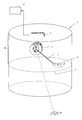
- the lever 5 is rotatably mounted at its other end, being ensured that attached magnet 4 participates this rotational movement.
- the sensor 3 is mounted, which in turn with an evaluation 11 communicates.
- the float 6 changes its position relative to the container height, whereby the lever 5 and the magnet 4 are moved, the magnet 4 its pole position to the sensor 3 and thus its magnetic field influence the sensor 3 is changed, which causes a change in the output signal of the sensor 3 in a known manner.
- the programming of the sensor 3 is preferably carried out in advance with knowledge of the container type, wherein, for example, each individual liter associated with a sensor signal and read into interpolation points. In practice, it has been found that a number of 32 interpolation points is sufficient to output a clean signal when Litern.
- the programming can also be done only when installed in the container 1.
- the definition and programming of the support points is thus individually to each container 1 in the installed state or with predetermined reference points.
- the ring magnet 4 is executed in a preferred embodiment as a sub-segment 4a and not as a solid ring. If in this case a thickness of approximately 1.1 outer diameter to inner diameter is maintained, this results in a linear field development, which increases the measuring accuracy of the level sensor 10.
Landscapes
- Physics & Mathematics (AREA)
- Fluid Mechanics (AREA)
- General Physics & Mathematics (AREA)
- Level Indicators Using A Float (AREA)
Abstract
Description
Die Programmierung des Sensors 3 erfolgt bei Kenntnis des Behältertyps vorzugsweise vorab, wobei beispielsweise jedem einzelnen Liter ein Sensorsignal zugeordnet und in Stützstellen eingelesen wird. In der Praxis hat sich gezeigt, daß eine Anzahl von 32 Stützstellen ausreichend ist, um beim Litern ein sauberes Signal auszugeben. Die Programmierung kann aber auch erst beim Einbau in den Behälter 1 erfolgen. Die Festlegung und Programmierung der Stützstellen erfolgt also individuell an jeden Behälter 1 im verbauten Zustand oder mit vorab festgelegten Referenzpunkten.
Der Ringmagnet 4 ist in einer bevorzugten Ausführung als Teilsegment 4a und nicht als Vollring ausgeführt. Wird hierbei eine Dicke von ca. 1,1 Außendurchmesser zu Innendurchmesser eingehalten, ergibt dies eine lineare Feldabwicklung, was Meßgenauigkeit der Füllstandssensorik 10 erhöht.
Claims (10)
- Füllstandssensorik (10) für Flüssigkeitsbehälter (1), vorzugsweise für einen Kraftstoffbehälter für ein Kraftfahrzeug, aufweisend einen Hebelarm (5), an dessen einem Ende ein Schwimmer (6) angebracht und dessen anderes Ende drehbar gelagert ist und mit einem Ringmagneten (4) in funktionaler Verbindung steht, dem ein Sensor (3) zugeordnet ist, welcher programmierbar ist, wobei bei Auslenkung des Hebels (5) der Ringmagnet (4) mit ausgelenkt wird, so daß dieser seinen magnetischen Einfluß auf den Sensor (3) verändert, was ein dem Füllstand entsprechendes Ausgangssignal bewirkt.
- Füllstandssensorik nach Anspruch 1, dadurch gekennzeichnet, daß der programmierbare Sensor (3) ein Hall-Sensor ist.
- Füllstandssensorik nach Anspruch 1 oder 2, dadurch gekennzeichnet, daß der Ringmagnet (4) sehr dünn ausgeführt ist, so daß seine Feldabwicklung selbst linear ist.
- Füllstandssensorik nach einem der Ansprüche 1 bis 3, dadurch gekennzeichnet, daß der Ringmagnet (4) durch einen Teilsegment-Ringmagnet (4a) gebildet wird.
- Füllstandssensorik nach Anspruch 2, dadurch gekennzeichnet, daß der Hall-Sensor über freiprogrammierbare Stützstellen verfügt.
- Füllstandssensorik nach Anspruch 5, dadurch gekennzeichnet, daß die Festlegung und Programmierung der Stützstellen entweder individuell an jeden Behälter (1) im verbauten Zustand oder mit vorab festgelegten Referenzpunkten erfolgt.
- Füllstandssensorik nach Anspruch 5 oder 6, dadurch gekennzeichnet, daß bei der individuellen Festlegung des Stützstellen bzw. Referenzpunkten im Behälter (1) einzelne Positionen bzw. Stellungen der Hebels (5) bestimmten Ausgangssignalgrößen am Sonsor (3) zugeordnet werden, so daß für jeden Behältertyp eine zugehörige Signalausgangskennlinie erzeugt wird.
- Füllstandssensorik nach einem der Ansprüche 1 bis 7, dadurch gekennzeichnet, daß mechanische Toleranzen des Behälters (1) sowie der Füllstandssensorik (10) selbst eliminiert werden können.
- Füllstandssensorik nach einem der Ansprüche 1 bis 8, dadurch gekennzeichnet, daß das Ausgangssignal des Sensors (3) als analoges als auch als digitales Signal ausgegeben wird.
- Füllstandssensorik nach einem der Ansprüche 1 bis 9, gekennzeichnet durch eine eigene Diagnosefähigkeit.
Applications Claiming Priority (2)
| Application Number | Priority Date | Filing Date | Title |
|---|---|---|---|
| DE10156479 | 2001-11-16 | ||
| DE2001156479 DE10156479A1 (de) | 2001-11-16 | 2001-11-16 | Berührungslose Füllstandssensorik |
Publications (3)
| Publication Number | Publication Date |
|---|---|
| EP1312898A2 true EP1312898A2 (de) | 2003-05-21 |
| EP1312898A3 EP1312898A3 (de) | 2003-12-03 |
| EP1312898B1 EP1312898B1 (de) | 2011-07-20 |
Family
ID=7706076
Family Applications (1)
| Application Number | Title | Priority Date | Filing Date |
|---|---|---|---|
| EP02018548A Expired - Lifetime EP1312898B1 (de) | 2001-11-16 | 2002-08-17 | Berührungslose Füllstandssensorik |
Country Status (3)
| Country | Link |
|---|---|
| EP (1) | EP1312898B1 (de) |
| DE (1) | DE10156479A1 (de) |
| ES (1) | ES2370926T3 (de) |
Cited By (7)
| Publication number | Priority date | Publication date | Assignee | Title |
|---|---|---|---|---|
| EP1355134A1 (de) * | 2002-04-11 | 2003-10-22 | Pierburg GmbH | Flüssigkeitsfüllstandsmesser |
| EP1690068A4 (de) * | 2003-11-17 | 2007-10-17 | Nartron Corp | Kraftstoffpegelsensor |
| CN102965862A (zh) * | 2012-12-05 | 2013-03-13 | 上海富山精密机械科技有限公司 | 工业缝纫机的油量检测与报警机构 |
| WO2015160449A1 (en) * | 2014-04-17 | 2015-10-22 | Deringer-Ney, Inc. | Apparatuses and methods for fuel level sensing |
| CN105675087A (zh) * | 2016-01-26 | 2016-06-15 | 广州竞标汽车零部件制造有限公司 | 一种燃油泵磁感应液位传感器系统 |
| US9435680B2 (en) | 2014-03-24 | 2016-09-06 | Deringer-Ney, Inc. | Apparatuses and methods for fuel level sensing |
| US9488515B2 (en) | 2014-03-24 | 2016-11-08 | Deringer-Ney, Inc. | Apparatuses and methods for fuel level sensing |
Families Citing this family (4)
| Publication number | Priority date | Publication date | Assignee | Title |
|---|---|---|---|---|
| JP4619685B2 (ja) * | 2004-05-07 | 2011-01-26 | 矢崎総業株式会社 | フロ−トを用いた液面レベルセンサ及びフロ−トを用いた液面レベル検出方法 |
| DE102011088816A1 (de) * | 2011-12-16 | 2013-06-20 | Continental Automotive Gmbh | Füllstandsgeber in einem Kraftstoffbehälter eines Kraftfahrzeugs, Herstellverfahren für einen solchen Füllstandsgeber und Verfahren zum Betreiben eines solchen Füllstandsgebers |
| ES2478740B1 (es) * | 2012-12-20 | 2015-04-28 | Enrique PUERTA BLANCO | Sonda para determinar el nivel de la fase líquida de gases licuados del petróleo y otros gases licuados, acondicionados en botellas presurizadas |
| DE102014006276A1 (de) | 2014-05-02 | 2015-11-05 | Meas Deutschland Gmbh | Messvorrichtung sowie Verfahren zum Messen des Pegels einer Flüssigkeit in einem Behälter |
Family Cites Families (2)
| Publication number | Priority date | Publication date | Assignee | Title |
|---|---|---|---|---|
| DE2627865A1 (de) * | 1976-06-22 | 1978-01-05 | Vdo Schindling | Fuellstands-messeinrichtung |
| WO1988001046A1 (en) * | 1986-07-28 | 1988-02-11 | Qualitrol Corporation | Hall effect liquid level sensor system |
-
2001
- 2001-11-16 DE DE2001156479 patent/DE10156479A1/de not_active Withdrawn
-
2002
- 2002-08-17 ES ES02018548T patent/ES2370926T3/es not_active Expired - Lifetime
- 2002-08-17 EP EP02018548A patent/EP1312898B1/de not_active Expired - Lifetime
Cited By (8)
| Publication number | Priority date | Publication date | Assignee | Title |
|---|---|---|---|---|
| EP1355134A1 (de) * | 2002-04-11 | 2003-10-22 | Pierburg GmbH | Flüssigkeitsfüllstandsmesser |
| EP1690068A4 (de) * | 2003-11-17 | 2007-10-17 | Nartron Corp | Kraftstoffpegelsensor |
| US7530269B2 (en) | 2003-11-17 | 2009-05-12 | Nartron Corporation | Fuel level sensor |
| CN102965862A (zh) * | 2012-12-05 | 2013-03-13 | 上海富山精密机械科技有限公司 | 工业缝纫机的油量检测与报警机构 |
| US9435680B2 (en) | 2014-03-24 | 2016-09-06 | Deringer-Ney, Inc. | Apparatuses and methods for fuel level sensing |
| US9488515B2 (en) | 2014-03-24 | 2016-11-08 | Deringer-Ney, Inc. | Apparatuses and methods for fuel level sensing |
| WO2015160449A1 (en) * | 2014-04-17 | 2015-10-22 | Deringer-Ney, Inc. | Apparatuses and methods for fuel level sensing |
| CN105675087A (zh) * | 2016-01-26 | 2016-06-15 | 广州竞标汽车零部件制造有限公司 | 一种燃油泵磁感应液位传感器系统 |
Also Published As
| Publication number | Publication date |
|---|---|
| DE10156479A1 (de) | 2003-05-28 |
| EP1312898A3 (de) | 2003-12-03 |
| EP1312898B1 (de) | 2011-07-20 |
| ES2370926T3 (es) | 2011-12-23 |
Similar Documents
| Publication | Publication Date | Title |
|---|---|---|
| EP1445494B1 (de) | Stellelement mit Lageerkennung | |
| EP2414706B1 (de) | Vorrichtung zur erfassung der position eines fahrstufenwählhebels und kraftfahrzeug, das damit ausgestattet ist | |
| EP1503912B1 (de) | Gummilager mit einfederungssensor | |
| EP1269054B1 (de) | Stellungsregler, insbesondere für ein durch einen antrieb betätigbares ventil | |
| EP0075693B2 (de) | Gangwähler für ein Getriebe | |
| EP1312898B1 (de) | Berührungslose Füllstandssensorik | |
| DE102009055104A1 (de) | Magnetfeldsensoranordnung zur Wegerfassung an beweglichen Bauteilen | |
| DE69014911T2 (de) | Füllstandsensor für Fluide. | |
| DE19749330C2 (de) | Vorrichtung zum Erfassen von Schaltstellungen eines mechanisch betätigbaren Schaltmittels | |
| EP2304274B1 (de) | Verfahren zum kalibrieren eines positionssensors in einem kraftfahrzeuggetriebe | |
| EP0953494A2 (de) | Vorrichtung zur Bestimmung des Masses der Verdrehung zwischen zwei Teilen | |
| EP0646775A1 (de) | Vorrichtung zur Drehwinkeldetektierung | |
| DE19843437A1 (de) | Füllstandsmeßeinrichtung | |
| DE3709717C2 (de) | Meßgerät, insbesondere Waage | |
| WO1998057128A1 (de) | Wegsensor | |
| EP1471337B1 (de) | Vorrichtung zur Messung des Füllstands einer in einem Behälter aufgenommenen Flüssigkeit | |
| EP1131605B1 (de) | Messvorrichtung zur berührunglosen erfassung eines drehwinkels | |
| DE10348914B4 (de) | Vorrichtung zum Messen des Drehwinkels eines Drehkörpers | |
| EP2891024B1 (de) | Bedienvorrichtung für eine funktionseinrichtung eines kraftfahrzeugs | |
| DE102011118773A1 (de) | Vorrichtung zur berührungslosen Erfassung der Relativposition zweier relativ zueinander bewegbarer Teile | |
| DE19926895A1 (de) | Messeinrichtung zur Ermittlung der Stellung eines Stellorgans | |
| DE102007052978A1 (de) | Anordnung zur Erfassung eines Drehwinkels | |
| EP1156249A1 (de) | Einrichtung zur Befestigung eines Magneten, sowie Stellungsregler mit einer derartigen Einrichtung. | |
| EP1126252B1 (de) | Füllstandsgeber für einen Kraftstofftank | |
| DE3233936A1 (de) | Einrichtung zum messen des fuellstandes von fluessiggas in einem zylinderfoermigen fluessiggastank eines kraftfahrzeuges |
Legal Events
| Date | Code | Title | Description |
|---|---|---|---|
| PUAI | Public reference made under article 153(3) epc to a published international application that has entered the european phase |
Free format text: ORIGINAL CODE: 0009012 |
|
| 17P | Request for examination filed |
Effective date: 20020817 |
|
| AK | Designated contracting states |
Designated state(s): AT BE BG CH CY CZ DE DK EE ES FI FR GB GR IE IT LI LU MC NL PT SE SK TR |
|
| AX | Request for extension of the european patent |
Extension state: AL LT LV MK RO SI |
|
| PUAL | Search report despatched |
Free format text: ORIGINAL CODE: 0009013 |
|
| RAP1 | Party data changed (applicant data changed or rights of an application transferred) |
Owner name: TI AUTOMOTIVE (NEUSS) GMBH |
|
| AK | Designated contracting states |
Kind code of ref document: A3 Designated state(s): AT BE BG CH CY CZ DE DK EE ES FI FR GB GR IE IT LI LU MC NL PT SE SK TR |
|
| AX | Request for extension of the european patent |
Extension state: AL LT LV MK RO SI |
|
| AKX | Designation fees paid |
Designated state(s): DE ES FR GB IT |
|
| 17Q | First examination report despatched |
Effective date: 20070219 |
|
| GRAP | Despatch of communication of intention to grant a patent |
Free format text: ORIGINAL CODE: EPIDOSNIGR1 |
|
| GRAS | Grant fee paid |
Free format text: ORIGINAL CODE: EPIDOSNIGR3 |
|
| GRAA | (expected) grant |
Free format text: ORIGINAL CODE: 0009210 |
|
| AK | Designated contracting states |
Kind code of ref document: B1 Designated state(s): DE ES FR GB IT |
|
| REG | Reference to a national code |
Ref country code: GB Ref legal event code: FG4D Free format text: NOT ENGLISH Ref country code: DE Ref legal event code: R081 Ref document number: 50215130 Country of ref document: DE Owner name: TI AUTOMOTIVE TECHNOLOGY CENTER GMBH, DE Free format text: FORMER OWNER: PIERBURG GMBH, 41460 NEUSS, DE |
|
| REG | Reference to a national code |
Ref country code: DE Ref legal event code: R096 Ref document number: 50215130 Country of ref document: DE Effective date: 20110908 |
|
| PGFP | Annual fee paid to national office [announced via postgrant information from national office to epo] |
Ref country code: FR Payment date: 20110830 Year of fee payment: 10 Ref country code: ES Payment date: 20110826 Year of fee payment: 10 Ref country code: GB Payment date: 20110825 Year of fee payment: 10 |
|
| REG | Reference to a national code |
Ref country code: ES Ref legal event code: FG2A Ref document number: 2370926 Country of ref document: ES Kind code of ref document: T3 Effective date: 20111223 |
|
| PLBE | No opposition filed within time limit |
Free format text: ORIGINAL CODE: 0009261 |
|
| STAA | Information on the status of an ep patent application or granted ep patent |
Free format text: STATUS: NO OPPOSITION FILED WITHIN TIME LIMIT |
|
| 26N | No opposition filed |
Effective date: 20120423 |
|
| REG | Reference to a national code |
Ref country code: DE Ref legal event code: R097 Ref document number: 50215130 Country of ref document: DE Effective date: 20120423 |
|
| GBPC | Gb: european patent ceased through non-payment of renewal fee |
Effective date: 20120817 |
|
| REG | Reference to a national code |
Ref country code: FR Ref legal event code: ST Effective date: 20130430 |
|
| PG25 | Lapsed in a contracting state [announced via postgrant information from national office to epo] |
Ref country code: IT Free format text: LAPSE BECAUSE OF NON-PAYMENT OF DUE FEES Effective date: 20120817 |
|
| PG25 | Lapsed in a contracting state [announced via postgrant information from national office to epo] |
Ref country code: GB Free format text: LAPSE BECAUSE OF NON-PAYMENT OF DUE FEES Effective date: 20120817 |
|
| PG25 | Lapsed in a contracting state [announced via postgrant information from national office to epo] |
Ref country code: FR Free format text: LAPSE BECAUSE OF NON-PAYMENT OF DUE FEES Effective date: 20120831 |
|
| REG | Reference to a national code |
Ref country code: ES Ref legal event code: FD2A Effective date: 20131218 |
|
| PG25 | Lapsed in a contracting state [announced via postgrant information from national office to epo] |
Ref country code: ES Free format text: LAPSE BECAUSE OF NON-PAYMENT OF DUE FEES Effective date: 20120818 |
|
| REG | Reference to a national code |
Ref country code: DE Ref legal event code: R081 Ref document number: 50215130 Country of ref document: DE Owner name: TI AUTOMOTIVE TECHNOLOGY CENTER GMBH, DE Free format text: FORMER OWNER: TI AUTOMOTIVE (NEUSS) GMBH, 41460 NEUSS, DE |
|
| PGFP | Annual fee paid to national office [announced via postgrant information from national office to epo] |
Ref country code: DE Payment date: 20210819 Year of fee payment: 20 |
|
| REG | Reference to a national code |
Ref country code: DE Ref legal event code: R071 Ref document number: 50215130 Country of ref document: DE |