EP1312801A2 - Fuel cooled pumping stage for high pressure fuel pump - Google Patents
Fuel cooled pumping stage for high pressure fuel pump Download PDFInfo
- Publication number
- EP1312801A2 EP1312801A2 EP02017505A EP02017505A EP1312801A2 EP 1312801 A2 EP1312801 A2 EP 1312801A2 EP 02017505 A EP02017505 A EP 02017505A EP 02017505 A EP02017505 A EP 02017505A EP 1312801 A2 EP1312801 A2 EP 1312801A2
- Authority
- EP
- European Patent Office
- Prior art keywords
- pump
- piston
- fuel
- ring channel
- pressure
- Prior art date
- Legal status (The legal status is an assumption and is not a legal conclusion. Google has not performed a legal analysis and makes no representation as to the accuracy of the status listed.)
- Withdrawn
Links
Images
Classifications
-
- F—MECHANICAL ENGINEERING; LIGHTING; HEATING; WEAPONS; BLASTING
- F04—POSITIVE - DISPLACEMENT MACHINES FOR LIQUIDS; PUMPS FOR LIQUIDS OR ELASTIC FLUIDS
- F04B—POSITIVE-DISPLACEMENT MACHINES FOR LIQUIDS; PUMPS
- F04B1/00—Multi-cylinder machines or pumps characterised by number or arrangement of cylinders
- F04B1/04—Multi-cylinder machines or pumps characterised by number or arrangement of cylinders having cylinders in star- or fan-arrangement
- F04B1/0404—Details or component parts
-
- F—MECHANICAL ENGINEERING; LIGHTING; HEATING; WEAPONS; BLASTING
- F04—POSITIVE - DISPLACEMENT MACHINES FOR LIQUIDS; PUMPS FOR LIQUIDS OR ELASTIC FLUIDS
- F04B—POSITIVE-DISPLACEMENT MACHINES FOR LIQUIDS; PUMPS
- F04B53/00—Component parts, details or accessories not provided for in, or of interest apart from, groups F04B1/00 - F04B23/00 or F04B39/00 - F04B47/00
- F04B53/08—Cooling; Heating; Preventing freezing
Definitions
- the invention relates to a pump element for a Piston pump according to the generic terms of the subordinate Claims 1 and 4 and a piston pump according to the General term of the secondary claim 7
- High pressure fuel pumps especially at High pressure fuel pumps of internal combustion engines with Gasoline direct injection, it is known that during the Operating temperatures so high that local Steam bubbles arise.
- These vapor bubbles are in several Regardless undesirable: First of all, steam bubbles in the Delivery space of the pump element (s) the delivery behavior of the high-pressure fuel pump. To the second, vapor bubble formation in the area of the Piston tread to tear off the lubricating film and thus lead to a piston seizure.
- the invention has for its object pump elements for a high pressure fuel pump and a high pressure fuel pump to provide that are simply constructed and the unwanted vapor bubble formation is reliable is avoided.
- This task is for a pump element for a Piston pump for high-pressure fuel generation Fuel injection systems of internal combustion engines, with at least one in a cylinder bore Cylinder bushing arranged piston, the Cylinder sleeve has a cylinder jacket and the Piston has a piston skirt, solved in that between the cylinder jacket and a pump housing Piston pump a first ring channel for cooling the Pump element is formed.
- Both embodiments are in terms of cooling performance as well as. It can be one or the other Embodiment depending on the other circumstances of the High-pressure fuel pump are preferred.
- Lubrication of the piston skirt in the cylinder bore can be significantly improved if in the piston skirt a second annular groove is provided and this second annular groove together with the cylinder bore a second ring channel for lubricating and cooling the piston.
- This one too second ring channel can of fuel, which of the Pre-feed pump is pumped, flowed through and thus cause cooling and lubrication of the piston. in the second ring channel prevails about the delivery pressure of the Pre-feed pump with a pressure corresponding to about 4 to 6 bar, as a result, the Evaporation temperature of the fuel increases what a additional security against the formation of steam bubbles offers.
- the so cooled and lubricated pistons of the pump element always by a stable lubricating film separated from the cylinder bore, see above that the piston is very low-wear in the Cylinder bore is guaranteed.
- a pump element for a piston pump High pressure fuel generation at Fuel injection systems of internal combustion engines with at least one in a cylinder bore Cylinder bushing arranged piston, the Cylinder sleeve has a cylinder jacket and the Piston has a piston skirt, solved in that in Piston shaft a second annular groove is provided and that the second ring groove together with the cylinder bore second ring channel for lubrication and cooling of the piston forms.
- This pump element has the advantages mentioned above a pump element with a second annular groove. It has showed that the existence of the second Ring groove and the second ring channel is sufficient for cooling and lubrication of the piston in all operating states ensure and the formation of steam bubbles to suppress effectively.
- Cylinder liner and piston can be provided in that Cylinder jacket a first annular groove is provided and that the first ring groove together with the pump housing Piston pump a first annular gap for cooling the Pump element forms.
- High-pressure fuel pump is provided for in the Pump housing a first hydraulic connection between a fuel supply on the one hand and the first Ring channel and / or the second ring channel on the other hand is available. Through this first hydraulic connection become the first ring channel and / or the second ring channel in a simple way of fuel, which of the Pre-feed pump conveyed to the high-pressure fuel pump is flowed through and thus the desired cooling occurs and lubrication of the cylinder liner and the piston.
- a quantity control valve be provided, which the tax amount in the first discharges hydraulic connection.
- the above The pressure damper also dampens that of the discharge quantity caused pressure surges on the suction side of the high-pressure fuel pump.
- a throttle is provided so that the drain of the pre-feed pump in the first and / or second Ring channel fuel is easily possible and the throttle, the amount of fuel, which by the flows first and / or second ring channel, as needed can be adjusted.
- the high-pressure fuel pump according to the invention is especially for use in those working according to the Otto principle Internal combustion engines, especially with direct petrol injection, suitable.
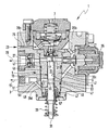
- the only figure shows an embodiment of a High-pressure fuel pump according to the invention in section.
- an embodiment is one High-pressure fuel pump 1 according to the invention Cross section shown.
- the High-pressure fuel pump 1 are a pump element 5 and a pressure damper 7 is used.
- the pump element 5 has et al a cylinder liner 9 and a piston 11 with a Piston shaft 13.
- the piston 11 is with his Piston shaft 13 in a cylinder bore 15 Cylinder bushing 9 out.
- a Pre-feed pump delivers fuel a fuel tank, also not shown, in the Fuel inlet 23.
- the delivery head of this prefeed pump is usually between 4 bar and 6 bar.
- the high pressure side 29 is with one or more injection nozzles, not shown hydraulically connected.
- the inlet valve 21 opens when the piston 11 is down from the inlet valve 21 removed, so that the volume of the delivery chamber 19 increases. As soon as the piston 11 reverses its direction of movement and the volume of the delivery chamber 19 is reduced again, that is Inlet valve 21 closed.
- the outlet valve 27 opens as soon as the pressure in the delivery chamber 19 is greater than on the high pressure side 29 of the high pressure fuel pump 1.
- the required oscillating motion of the piston 11 in the cylinder bore 15 is from one in the figure not shown drive, which on a second end 31 of the piston 11 acts, pronounced.
- This one Drive device not shown, can Camshaft in the cylinder head of the internal combustion engine, one Eccentric shaft or something comparable. So that Piston 11 impressed on it by the drive device oscillating movement in both directions between the second end 31 of the piston and the A compression spring 33 is clamped in the cylinder liner 9.
- the Compression spring 33 causes the second end 31 of the piston 11 always on the cam or the eccentric section the drive device rests.
- the delivery rate of the high-pressure fuel pump according to the invention is controlled by a volume control valve 35 controlled.
- the quantity control valve 35 is via a Connection bore 37 with the delivery chamber 19 hydraulically in Connection. Once the piston is out of fuel has conveyed the delivery chamber 19 to the high pressure side 29, opens the quantity control valve 35, so that the further from Piston 11 no longer delivered fuel High pressure side 29 arrives, but on the Connection bore 37 and a first hydraulic Connection 39 to the pressure damper 7 is promoted.
- the first hydraulic connection 39 has several Sections in the figure with 39a, 39b, 39c and 39d be designated.
- the discharge amount from the delivery room 19 flows through the connection bore 37 and the section 39b the first hydraulic connection to the pressure damper 7.
- the Fuel inlet 23 is the first over a section 39a hydraulic connection 39 in turn with the pressure damper 7 hydraulically connected. Over a section 39c of the first hydraulic connection 39 can not by the Pre-feed pump shown in the fuel inlet 23 in the fuel high-pressure pump 1 delivered fuel in a first ring channel 41 between a cylinder jacket 43 the cylinder liner 9 and a receiving bore 45 of the Flow the pump housing 3.
- the first ring channel 41 through a paragraph in the Cylinder jacket 43 and a paragraph in the stepped executed receiving bore 45 formed.
- fuel flows continuously from the fuel inlet 23 via the first hydraulic connection 39a, 39b and 39c. As a result, the cylinder liner 9 is cooled and as a result also the piston 11.
- the second ring channel 53 Leakage space 57 is provided, which has a second Connection bore 59 the amount of leakage to the fuel outlet 51 leads away. Between the throttle 49 and the Fuel drain 51 is a second hydraulic connection 61 is provided, into which the second connecting bore 59 empties. By dimensioning the throttle 49, the Fuel flow through the first hydraulic Connection 39 flows into the first ring channel 41, can be set.
- the second ring channel 53 is with the Form pressurized, which stabilizes the Lubricant film leads.
Landscapes
- Engineering & Computer Science (AREA)
- Mechanical Engineering (AREA)
- General Engineering & Computer Science (AREA)
- Fuel-Injection Apparatus (AREA)
- Structures Of Non-Positive Displacement Pumps (AREA)
Abstract
Description
Die Erfindung betrifft ein Pumpenelement für eine
Kolbenpumpe nach den Oberbegriffen der nebengeordneten
Ansprüche 1 und 4 sowie eine Kolbenpumpe nach dem
Oberbegriff des nebengeordneten Anspruchs 7. Bei
Kraftstoffhochdruckpumpen, insbesondere bei
Kraftstoffhochdruckpumpen von Brennkraftmaschinen mit
Benzin-Direkteinspritzung, ist es bekannt, dass während des
Betriebes so hohe Temperaturen erreicht werden, dass lokal
Dampfblasen entstehen. Diese Dampfblasen sind in mehrerer
Hinsicht unerwünscht: Zum ersten können Dampfblasen im
Förderraum des oder der Pumpenelemente das Förderverhalten
der Kraftstoff-Hochdruckpumpe nachteilig beeinflussen. Zum
zweiten kann eine Dampfblasenbildung im Bereich der
Kolbenlauffläche zu einem Abreißen des Schmierfilms und
damit zu einem Kolbenfresser führen.The invention relates to a pump element for a
Piston pump according to the generic terms of the subordinate
Claims 1 and 4 and a piston pump according to the
General term of the
Der Erfindung liegt die Aufgabe zugrunde, Pumpenelemente für eine Kraftstoff-Hochdruckpumpe und eine Kraftstoff-Hochdruckpumpe bereitzustellen, die einfach aufgebaut sind, und bei der die unerwünschte Dampfblasenbildung zuverlässig vermieden wird. The invention has for its object pump elements for a high pressure fuel pump and a high pressure fuel pump to provide that are simply constructed and the unwanted vapor bubble formation is reliable is avoided.
Diese Aufgabe wird bei einem Pumpenelement für eine Kolbenpumpe zur Kraftstoffhochdruckerzeugung bei Kraftstoffeinspritzsystemen von Brennkraftmaschinen, mit mindestens einem in einer Zylinderbohrung einer Zylinderbuchse angeordneten Kolben, wobei die Zylinderbuchse einen Zylindermantel aufweist und wobei der Kolben einen Kolbenschaft aufweist, dadurch gelöst, dass zwischen Zylindermantel und einem Pumpengehäuse der Kolbenpumpe ein erster Ringkanal zur Kühlung des Pumpenelements ausgebildet ist.This task is for a pump element for a Piston pump for high-pressure fuel generation Fuel injection systems of internal combustion engines, with at least one in a cylinder bore Cylinder bushing arranged piston, the Cylinder sleeve has a cylinder jacket and the Piston has a piston skirt, solved in that between the cylinder jacket and a pump housing Piston pump a first ring channel for cooling the Pump element is formed.
Durch diesen ersten Ringkanal kann ein Kühlmedium, insbesondere Kraftstoff, gefördert werden, welches zuverlässig dafür sorgt, dass die Temperatur der Zylinderbuchse und damit auch des Kolbenschafts unterhalb der Verdampfungstemperatur des Kraftstoffs liegt. Die Förderung des Kraftstoffs durch den ersten Ringkanal kann durch die ohnehin vorhandene Vorförderpumpe der Kraftstoffeinspritzanlage erfolgen, so dass nahezu kein zusätzlicher Aufwand erforderlich ist, um die Zylinderbuchse und den Kolbenschaft zu kühlen.A cooling medium, especially fuel, which is promoted reliably ensures that the temperature of the Cylinder liner and thus the piston skirt below the vaporization temperature of the fuel. The Can deliver fuel through the first ring channel due to the pre-feed pump of the Fuel injection system take place, so almost none additional effort is required to the Cool the cylinder liner and the piston skirt.
Bei alternativen Ausgestaltungen der Erfindung kann entweder im Zylindermantel eine erste Ringnut vorgesehen sein und diese erste Ringnut zusammen mit dem Pumpengehäuse den ersten Ringkanal bilden oder die erste Ringnut im Pumpengehäuse vorgesehen sein und die erste Ringnut zusammen mit dem Zylindermantel den ersten Ringkanal zur Kühlung des Pumpenelements bilden.In alternative embodiments of the invention either a first annular groove is provided in the cylinder jacket be and this first ring groove together with the pump housing form the first ring channel or the first ring groove in Pump housing can be provided and the first annular groove together with the cylinder jacket the first ring channel Form cooling of the pump element.
Beide Ausführungsformen sind hinsichtlich der Kühlleistung gleich gut. Es kann der einen oder der anderen Ausführungsform je nach den sonstigen Gegebenheiten der Kraftstoff-Hochdruckpumpe der Vorzug gegeben werden. Both embodiments are in terms of cooling performance as well as. It can be one or the other Embodiment depending on the other circumstances of the High-pressure fuel pump are preferred.
Selbstverständlich ist es auch möglich, den Ringkanal durch eine teilweise in der Zylinderbuchse und teilweise im Gehäuse ausgearbeitete Ringnut zu bilden.Of course, it is also possible to pass through the ring channel partly in the cylinder liner and partly in the Formed housing to form an annular groove.
Die Schmierung des Kolbenschafts in der Zylinderbohrung kann entscheidend verbessert werden, wenn im Kolbenschaft eine zweite Ringnut vorgesehen ist und diese zweite Ringnut zusammen mit der Zylinderbohrung einen zweiten Ringkanal zur Schmierung und Kühlung des Kolbens bildet. Auch dieser zweite Ringkanal kann von Kraftstoff, welcher von der Vorförderpumpe gefördert wird, durchströmt werden und somit eine Kühlung und Schmierung des Kolbens bewirken. Im zweiten Ringkanal herrscht etwa ein dem Förderdruck der Vorförderpumpe von etwa 4 bis 6 bar entsprechender Druck, so dass sich in Folge dessen auch die Verdampfungstemperatur des Kraftstoffs erhöht, was eine zusätzliche Sicherheit gegen das Entstehen von Dampfblasen bietet. Im Ergebnis ist der solchermaßen gekühlte und geschmierte Kolben des Pumpenelements stets durch einen stabilen Schmierfilm von der Zylinderbohrung getrennt, so dass ein sehr verschleißarmer Lauf des Kolbens in der Zylinderbohrung gewährleistet ist.Lubrication of the piston skirt in the cylinder bore can be significantly improved if in the piston skirt a second annular groove is provided and this second annular groove together with the cylinder bore a second ring channel for lubricating and cooling the piston. This one too second ring channel can of fuel, which of the Pre-feed pump is pumped, flowed through and thus cause cooling and lubrication of the piston. in the second ring channel prevails about the delivery pressure of the Pre-feed pump with a pressure corresponding to about 4 to 6 bar, as a result, the Evaporation temperature of the fuel increases what a additional security against the formation of steam bubbles offers. As a result, the so cooled and lubricated pistons of the pump element always by a stable lubricating film separated from the cylinder bore, see above that the piston is very low-wear in the Cylinder bore is guaranteed.
Die eingangs genannte Aufgabe wird erfindungsgemäß auch gelöst durch ein Pumpenelement für eine Kolbenpumpe zur Kraftstoffhochdruckerzeugung bei Kraftstoffeinspritzsystemen von Brennkraftmaschinen, mit mindestens einem in einer Zylinderbohrung einer Zylinderbuchse angeordneten Kolben, wobei die Zylinderbuchse einen Zylindermantel aufweist und wobei der Kolben einen Kolbenschaft aufweist, dadurch gelöst, dass im Kolbenschaft eine zweite Ringnut vorgesehen ist und dass die zweite Ringnut zusammen mit der Zylinderbohrung einen zweiten Ringkanal zur Schmierung und Kühlung des Kolbens bildet. The task mentioned at the outset is also achieved according to the invention solved by a pump element for a piston pump High pressure fuel generation at Fuel injection systems of internal combustion engines, with at least one in a cylinder bore Cylinder bushing arranged piston, the Cylinder sleeve has a cylinder jacket and the Piston has a piston skirt, solved in that in Piston shaft a second annular groove is provided and that the second ring groove together with the cylinder bore second ring channel for lubrication and cooling of the piston forms.
Dieses Pumpenelement weist die oben genannten Vorteile eines Pumpenelements mit einer zweiten Ringnut auf. Es hat sich gezeigt, dass allein das Vorhandensein der zweiten Ringnut und des zweiten Ringkanals ausreicht, um Kühlung und Schmierung des Kolbens in allen Betriebszuständen zu gewährleisten und das Entstehen von Dampfblasen wirkungsvoll zu unterdrücken.This pump element has the advantages mentioned above a pump element with a second annular groove. It has showed that the existence of the second Ring groove and the second ring channel is sufficient for cooling and lubrication of the piston in all operating states ensure and the formation of steam bubbles to suppress effectively.
Zur weiteren Absenkung der Bauteiltemperaturen von Zylinderbüchse und Kolben kann vorgesehen sein, dass im Zylindermantel eine erste Ringnut vorgesehen ist und dass die erste Ringnut zusammen mit dem Pumpengehäuse der Kolbenpumpe einen ersten Ringspalt zur Kühlung des Pumpenelements bildet. Durch diese Maßnahme werden zusätzlich die weiter oben genannten Vorteile des ersten Ringkanals auch bei diesem Pumpenelement realisiert.To further reduce component temperatures from Cylinder liner and piston can be provided in that Cylinder jacket a first annular groove is provided and that the first ring groove together with the pump housing Piston pump a first annular gap for cooling the Pump element forms. Through this measure additionally the advantages of the first mentioned above Ring channel also realized with this pump element.
Die eingangs genannte Aufgabe wird ebenfalls gelöst bei einer Kraftstoff-Hochdruckpumpe für eine Einspritzanlage von Brennkraftmaschinen mit einem in einem Pumpengehäuse aufgenommenen Pumpenelement nach einem der vorhergehenden Ansprüche. Bei dieser Kraftstoff-Hochdruckpumpe stellen sich die oben genannten Vorteile der erfindungsgemäßen Pumpenelemente ein, so dass ein störungsfreier und verschleißarmer Betrieb der Kraftstoff-Hochdruckpumpe möglich wird.The task mentioned at the beginning is also solved at a high-pressure fuel pump for an injection system of internal combustion engines with one in a pump housing picked up pump element according to one of the preceding Expectations. Place on this high pressure fuel pump the above-mentioned advantages of the invention Pump elements so that a trouble-free and low-wear operation of the high-pressure fuel pump becomes possible.
Bei einer weiteren Ausgestaltung der erfindungsgemäßen Kraftstoff-Hochdruckpmpe ist vorgesehen, dass im Pumpengehäuse eine erste hydraulische Verbindung zwischen einem Kraftstoffzulauf einerseits sowie dem ersten Ringkanal und/oder dem zweiten Ringkanal andererseits vorhanden ist. Durch diese erste hydraulische Verbindung werden der erste Ringkanal und/oder der zweite Ringkanal auf einfache Weise von Kraftstoff, welcher von der Vorförderpumpe zur Kraftstoff-Hochdruckpumpe gefördert wird, durchströmt und somit tritt die gewünschte Kühlung und Schmierung der Zylinderbuchse und des Kolbens ein.In a further embodiment of the invention High-pressure fuel pump is provided for in the Pump housing a first hydraulic connection between a fuel supply on the one hand and the first Ring channel and / or the second ring channel on the other hand is available. Through this first hydraulic connection become the first ring channel and / or the second ring channel in a simple way of fuel, which of the Pre-feed pump conveyed to the high-pressure fuel pump is flowed through and thus the desired cooling occurs and lubrication of the cylinder liner and the piston.
Zur Vermeidung von Druckstößen in der Saugseite der Kraftstoff-Hochdruckpumpe kann erfindungsgemäß vorgesehen sein, einen Druckdämpfer zu installieren, wobei der Druckdämpfer die in der ersten hydraulischen Verbindung auftretenden Druckstöße dämpft.To avoid pressure surges in the suction side of the High-pressure fuel pump can be provided according to the invention be to install a pressure damper, the Pressure damper in the first hydraulic connection dampening occurring dampens.
Zur Regelung und Steuerung der Fördermenge der erfindungsgemäßen Kolbenpumpe kann ein Mengensteuerventil vorgesehen sein, welches die Absteuermenge in die erste hydraulische Verbindung abführt. Der oben genannte Druckdämpfer dämpft auch die von der Absteuermenge verursachten Druckstöße auf der Saugseite der Kraftstoff-Hochdruckpumpe.To regulate and control the flow rate of the Piston pump according to the invention can be a quantity control valve be provided, which the tax amount in the first discharges hydraulic connection. The above The pressure damper also dampens that of the discharge quantity caused pressure surges on the suction side of the high-pressure fuel pump.
In weiterer Ergänzung der Erfindung kann vorgesehen sein, dass im Pumpengehäuse eine zweite hydraulische Verbindung zwischen dem ersten Ringkanal und/oder dem zweiten Ringkanal einerseits und einem Kraftstoffrücklauf andererseits vorgesehen ist, und dass zwischen Kraftstoffrücklauf und erstem Ringkanal und/oder zweitem Ringkanal eine Drossel vorgesehen ist, so dass der Abfluss des von der Vorförderpumpe in den ersten und/oder zweiten Ringkanal geförderten Kraftstoffs ohne weiteres möglich ist und über die Drossel die Kraftstoffmenge, welche durch den ersten und/oder zweiten Ringkanal strömt, bedarfsgerecht eingestellt werden kann.In a further addition to the invention, it can be provided that that in the pump housing a second hydraulic connection between the first ring channel and / or the second Ring channel on the one hand and a fuel return on the other hand, and that between Fuel return and first ring channel and / or second Ring channel a throttle is provided so that the drain of the pre-feed pump in the first and / or second Ring channel fuel is easily possible and the throttle, the amount of fuel, which by the flows first and / or second ring channel, as needed can be adjusted.
Die erfindungsgemäße Kraftstoff-Hochdruckpumpe ist besonders zum Einsatz in nach dem Otto-Prizip arbeitenden Brennkraftmaschinen, insbesondere mit Benzin-Direkteinspritzung, geeignet.The high-pressure fuel pump according to the invention is especially for use in those working according to the Otto principle Internal combustion engines, especially with direct petrol injection, suitable.
Weitere Vorteile und vorteilhafte Ausgestaltungen der Erfindung sind der nachfolgenden Zeichnung und deren Beschreibung, sowie den Patentansprüchen entnehmbar.Further advantages and advantageous configurations of the Invention are the following drawing and their Description, as well as the patent claims.
Es zeigt die einzige Figur ein Ausführungsbeispiel einer erfindungsgemäßen Kraftstoff-Hochdruckpumpe im Schnitt.The only figure shows an embodiment of a High-pressure fuel pump according to the invention in section.
In der einzigen Figur ist ein Ausführungsbeispiel einer
erfindungsgemäßen Kraftstoff-Hochdruckpumpe 1 im
Querschnitt dargestellt. In ein Pumpengehäuse 3 der
Kraftstoff-Hochdruckpumpe 1 sind ein Pumpenelement 5 und
ein Druckdämpfer 7 eingesetzt. Das Pumpenelement 5 weist
u.a. eine Zylinderbuchse 9 und einen Kolben 11 mit einem
Kolbenschaft 13 auf. Der Kolben 11 ist mit seinem
Kolbenschaft 13 in einer Zylinderbohrung 15 der
Zylinderbuchse 9 geführt.In the single figure, an embodiment is one
High-pressure fuel pump 1 according to the invention
Cross section shown. In a
Mit einem ersten Ende 17 des Kolbens 11 begrenzt dieser
einen Förderraum 19 des Pumpenelements 5. Der Förderraum 19
steht über ein Einlassventil 21 mit einem Kraftstoffzulauf
23 hydraulisch in Verbindung. Der Weg des Kraftstoffs vom
Kraftstoffzulauf 23 in den Förderraum 19 über das
Einlassventil 21 ist durch einen Pfeil 25 angedeutet. Eine
nicht dargestellte Vorförderpumpe fördert Kraftstoff aus
einem ebenfalls nicht dargestellten Kraftstofftank in den
Kraftstoffzulauf 23. Die Förderhöhe dieser Vorförderpumpe
beträgt üblicherweise zwischen 4 bar und 6 bar.With a first end 17 of the piston 11, it delimits
a
Über ein Auslassventil 27 kann der Kraftstoff aus dem
Förderraum 19 zu einer Hochdruckseite 29 der Kraftstoff-Hochdruckpumpe
1 strömen. Die Hochdruckseite 29 ist mit
einer oder mehreren nicht dargestellten Einspritzdüsen
hydraulisch verbunden. Das Einlassventil 21 öffnet, wenn
der Kolben 11 sich vom Einlassventil 21 nach unten
entfernt, so dass das Volumen des Förderraums 19 zunimmt.
Sobald der Kolben 11 seine Bewegungsrichtung umkehrt und
das Volumen des Förderraums 19 wieder verkleinert, ist das
Einlassventil 21 geschlossen.Via an
Das Auslassventil 27 öffnet, sobald der Druck im Förderraum
19 größer ist als auf der Hochdruckseite 29 der Kraftstoff-Hochdruckpumpe
1. Die erforderliche oszillierende Bewegung
des Kolbens 11 in der Zylinderbohrung 15 wird von einem in
der Figur nicht dargestellten Antrieb, welcher auf ein
zweites Ende 31 des Kolbens 11 wirkt, ausgeprägt. Die hier
nicht dargestellte Antriebsvorrichtung kann eine
Nockenwelle im Zylinderkopf der Brennkraftmaschine, eine
Exzenterwelle oder etwas Vergleichbares sein. Damit der
Kolben 11 die ihm von der Antriebseinrichtung aufgeprägte
oszillierende Bewegung in beiden Richtungen mitmacht, ist
zwischen dem zweiten Ende 31 des Kolbens und der
Zylinderbuchse 9 eine Druckfeder 33 eingespannt. Die
Druckfeder 33 bewirkt, dass das zweite Ende 31 des Kolbens
11 stets auf dem Nocken oder dem exzentrischen Abschnitt
der Antriebseinrichtung aufliegt.The
Die Fördermenge der erfindungsgemäßen Kraftstoff-Hochdruckpumpe
wird durch ein Mengensteuerventil 35
gesteuert. Das Mengensteuerventil 35 ist über eine
Verbindungsbohrung 37 mit dem Förderraum 19 hydraulisch in
Verbindung. Sobald der Kolben ausreichend Kraftstoff aus
dem Förderraum 19 zur Hochdruckseite 29 gefördert hat,
öffnet das Mengensteuerventil 35, so dass der weitere vom
Kolben 11 geförderte Kraftstoff nicht mehr zur
Hochdruckseite 29 gelangt, sondern über die
Verbindungsbohrung 37 und eine erste hydraulische
Verbindung 39 zum Druckdämpfer 7 gefördert wird.The delivery rate of the high-pressure fuel pump according to the invention
is controlled by a
Die erste hydraulische Verbindung 39 hat verschiedene
Abschnitte, die in der Figur mit 39a, 39b, 39c und 39d
bezeichnet werden. Die Absteuermenge aus dem Förderraum 19
fließt über die Verbindungsbohrung 37 und den Abschnitt 39b
der ersten hydraulischen Verbindung zum Druckdämpfer 7. Der
Kraftstoffzulauf 23 ist über einen Abschnitt 39a der ersten
hydraulischen Verbindung 39 wiederum mit dem Druckdämpfer 7
hydraulisch verbunden. Über einen Abschnitt 39c der ersten
hydraulischen Verbindung 39 kann der von der nicht
dargestellten Vorförderpumpe in den Kraftstoffzulauf 23 in
die Kraftstoff-Hochdruckpumpe 1 geförderte Kraftstoff in
einen ersten Ringkanal 41 zwischen einem Zylindermantel 43
der Zylinderbuchse 9 und einer Aufnahmebohrung 45 des
Pumpengehäuses 3 strömen.The first hydraulic connection 39 has several
Sections in the figure with 39a, 39b, 39c and 39d
be designated. The discharge amount from the
Bei dem Ausführungsbeispiel gemäß der einzigen Figur ist
der erste Ringkanal 41 durch einen Absatz in dem
Zylindermantel 43 und einen Absatz in der gestuft
ausgeführten Aufnahmebohrung 45 gebildet. Alternativ kann
der erste Ringkanal 41 auch durch eine Ringnut in der
Zylinderbuchse (nicht dargestellt) und/oder eine Ringnut
(nicht dargestellt) in der Aufnahmebohrung 45 gebildet
werden. Damit aus dem ersten Ringkanal 41 keine Leckage
austritt, sind O-Ringe 47 zwischen Zylinderbuchse 9 und
Pumpengehäuse 3 vorgesehen. In den ersten Ringkanal 41
strömt permanent Kraftstoff aus dem Kraftstoffzulauf 23
über die erste hydraulische Verbindung 39a, 39b und 39c.
Dadurch wird die Zylinderbuchse 9 gekühlt und infolgedessen
auch der Kolben 11. Daraus resultiert eine verringerte
Neigung zur Dampfblasenbildung, was vor allem im Bereich
der Lauffläche zwischen Kolbenschaft 13 und Zylinderbohrung
15 von besonderer Bedeutung ist. Aus dem ersten Ringkanal
41 strömt der Kraftstoff über eine Drossel in einen
Kraftstoffablauf 51, welcher beispielsweise mit dem nicht
dargestellten Tank in Verbindung stehen kann.In the embodiment according to the single figure
the
Zur weiteren Verbesserung der Kühlung und Schmierung des
Kolbens 11 ist im Kolbenschaft 13 ein zweiter Ringkanal 53
vorgesehen, welcher durch eine zweite Ringnut 55 im
Kolbenschaft 13 gebildet wird. Über den Abschnitt 39d der
ersten hydraulischen Verbindung wird der zweite Ringkanal
53 mit Kraftstoff beaufschlagt. Infolgedessen wird ein
äußerst stabiler Schmierfilm zwischen Kolbenschaft 13 und
Zylinderbohrung 15 ausgebildet. Wegen der Förderhöhe von
etwa 4 bis 6 bar der nicht dargestellten Vorförderpumpe
herrscht im zweiten Ringkanal 53, ebenso wie im ersten
Ringkanal 41, ein Überdruck von 4 bis 6 bar, was die
Dampfblasenbildung weiter unterdrückt. Es hat sich gezeigt,
dass schon der erste Ringkanal 41 oder der zweite Ringkanal
53 alleine deutliche Verbesserungen hinsichtlich der
Lebensdauer und des Verschleißes des Pumpenelements 5
bringen. Durch die Kombination beider Maßnahmen kann die
Lebensdauer und das Betriebsverhalten der erfindungsgemäßen
Kraftstoffhochdruckpumpe 1 weiter verbessert werden.To further improve the cooling and lubrication of the
Piston 11 has a second annular channel 53 in
In der Figur ist unterhalb des zweiten Ringkanals 53 ein
Leckageraum 57 vorgesehen, welcher über eine zweite
Verbindungsbohrung 59 die Leckagemenge zum Kraftstoffablauf
51 abführt. Zwischen der Drossel 49 und dem
Kraftstoffablauf 51 ist eine zweite hydraulische Verbindung
61 vorgesehen, in welche die zweite Verbindungsbohrung 59
mündet. Durch die Bemessung der Drossel 49 kann der
Kraftstoffstrom, welcher durch die erste hydraulische
Verbindung 39 in den ersten Ringkanal 41 strömt,
eingestellt werden. Der zweite Ringkanal 53 wird mit dem
Vordruck beaufschlagt, was zu einer Stabilisierung des
Schmierfilms führt.In the figure is a below the second ring channel 53
Leakage space 57 is provided, which has a second
Connection bore 59 the amount of leakage to the
Claims (13)
Applications Claiming Priority (2)
| Application Number | Priority Date | Filing Date | Title |
|---|---|---|---|
| DE2001156428 DE10156428A1 (en) | 2001-11-16 | 2001-11-16 | Fuel-cooled pump element and high-pressure pump for a fuel injection system |
| DE10156428 | 2001-11-16 |
Publications (2)
| Publication Number | Publication Date |
|---|---|
| EP1312801A2 true EP1312801A2 (en) | 2003-05-21 |
| EP1312801A3 EP1312801A3 (en) | 2004-05-12 |
Family
ID=7706044
Family Applications (1)
| Application Number | Title | Priority Date | Filing Date |
|---|---|---|---|
| EP02017505A Withdrawn EP1312801A3 (en) | 2001-11-16 | 2002-08-06 | Fuel cooled pumping stage for high pressure fuel pump |
Country Status (3)
| Country | Link |
|---|---|
| EP (1) | EP1312801A3 (en) |
| JP (1) | JP2003222062A (en) |
| DE (1) | DE10156428A1 (en) |
Cited By (3)
| Publication number | Priority date | Publication date | Assignee | Title |
|---|---|---|---|---|
| AT500996A1 (en) * | 2004-10-22 | 2006-05-15 | Bosch Gmbh Robert | HIGH PRESSURE PUMP ARRANGEMENT |
| CN111480000A (en) * | 2017-12-26 | 2020-07-31 | 日立汽车系统株式会社 | Fuel supply pump |
| CN111577594A (en) * | 2020-06-09 | 2020-08-25 | 阿奥艾斯能源科技成都有限公司 | Structure for cooling between power end and hydraulic end of plunger pump for shale gas exploitation |
Families Citing this family (3)
| Publication number | Priority date | Publication date | Assignee | Title |
|---|---|---|---|---|
| SE530565C2 (en) | 2006-11-10 | 2008-07-08 | Scania Cv Ab | A fuel pump device |
| JP5240284B2 (en) | 2010-12-10 | 2013-07-17 | 株式会社デンソー | Fuel supply pump |
| DE102012218552B4 (en) * | 2012-10-11 | 2016-03-24 | Continental Automotive Gmbh | pump |
Citations (5)
| Publication number | Priority date | Publication date | Assignee | Title |
|---|---|---|---|---|
| DE831038C (en) * | 1941-11-18 | 1952-02-11 | Friedrich Wilhelm Deckel Dipl | Fuel injection pump for internal combustion engines |
| DE3720888A1 (en) * | 1986-06-24 | 1988-01-07 | Diesel Kiki Co | COMBINED PUMP |
| EP0757174A2 (en) * | 1995-07-31 | 1997-02-05 | WOODWARD GOVERNOR GERMANY GmbH | Method of changing the timing of fuel injection pumps on a fuel injection pump thereof |
| EP1076174A2 (en) * | 1999-08-13 | 2001-02-14 | Robert Bosch Gmbh | Single cylinder high pressure pump |
| EP1143138A1 (en) * | 2000-04-03 | 2001-10-10 | Wärtsilä NSD Schweiz AG | Fuel injection pump |
Family Cites Families (1)
| Publication number | Priority date | Publication date | Assignee | Title |
|---|---|---|---|---|
| FI89972C (en) * | 1991-03-05 | 1993-12-10 | Waertsilae Diesel Int | Arrangement for lubrication of the piston member at a fuel injection pump p |
-
2001
- 2001-11-16 DE DE2001156428 patent/DE10156428A1/en not_active Ceased
-
2002
- 2002-08-06 EP EP02017505A patent/EP1312801A3/en not_active Withdrawn
- 2002-11-18 JP JP2002333764A patent/JP2003222062A/en active Pending
Patent Citations (5)
| Publication number | Priority date | Publication date | Assignee | Title |
|---|---|---|---|---|
| DE831038C (en) * | 1941-11-18 | 1952-02-11 | Friedrich Wilhelm Deckel Dipl | Fuel injection pump for internal combustion engines |
| DE3720888A1 (en) * | 1986-06-24 | 1988-01-07 | Diesel Kiki Co | COMBINED PUMP |
| EP0757174A2 (en) * | 1995-07-31 | 1997-02-05 | WOODWARD GOVERNOR GERMANY GmbH | Method of changing the timing of fuel injection pumps on a fuel injection pump thereof |
| EP1076174A2 (en) * | 1999-08-13 | 2001-02-14 | Robert Bosch Gmbh | Single cylinder high pressure pump |
| EP1143138A1 (en) * | 2000-04-03 | 2001-10-10 | Wärtsilä NSD Schweiz AG | Fuel injection pump |
Cited By (3)
| Publication number | Priority date | Publication date | Assignee | Title |
|---|---|---|---|---|
| AT500996A1 (en) * | 2004-10-22 | 2006-05-15 | Bosch Gmbh Robert | HIGH PRESSURE PUMP ARRANGEMENT |
| CN111480000A (en) * | 2017-12-26 | 2020-07-31 | 日立汽车系统株式会社 | Fuel supply pump |
| CN111577594A (en) * | 2020-06-09 | 2020-08-25 | 阿奥艾斯能源科技成都有限公司 | Structure for cooling between power end and hydraulic end of plunger pump for shale gas exploitation |
Also Published As
| Publication number | Publication date |
|---|---|
| JP2003222062A (en) | 2003-08-08 |
| EP1312801A3 (en) | 2004-05-12 |
| DE10156428A1 (en) | 2003-06-12 |
Similar Documents
| Publication | Publication Date | Title |
|---|---|---|
| DE19522306B4 (en) | High-pressure fuel supply pump | |
| DE112011105591B4 (en) | Fuel pump and fuel delivery system for internal combustion engine | |
| DE102013100845B4 (en) | Fuel feed pump | |
| DE10345406A1 (en) | High pressure pump for especially common rail fuel injection systems in internal combustion engines has individual modular feed pump units joined together in series by housings which have fluid connecting passages | |
| DE102009006963A1 (en) | Oil supply | |
| DE112018005595T5 (en) | Fuel supply pump | |
| DE102009000857A1 (en) | Pump arrangement for use in fuel injection system of air-compressed, self-igniting internal combustion engine, has suction valve for filling pump operating chamber of pump component with diesel fuel from recess of housing | |
| EP1911964A1 (en) | High-pressure fuel pump and fuel injection system for a combustion engine | |
| EP2954192B1 (en) | High pressure pump | |
| DE10129449A1 (en) | High-pressure fuel pump for internal combustion engines with improved part-load behavior | |
| EP1312801A2 (en) | Fuel cooled pumping stage for high pressure fuel pump | |
| DE19951144A1 (en) | Injector for fuel injection system in IC engines has guide bore in hydraulic connection with leakage oil return, to create pressure differential between pressure chamber and leakage oil return | |
| EP1395753B1 (en) | High-pressure pump for a fuel system of an internal combustion engine | |
| DE10261780A1 (en) | Fuel injection device for an internal combustion engine comprises valve element having a sealing surface interacting with valve seat to completely close an inlet opening when the sealing surface lies on the valve seat | |
| DE19945785B4 (en) | Fuel injection system for internal combustion engines and method for injecting fuel into the combustion chamber of an internal combustion engine | |
| EP0502315A1 (en) | Fuel injection pump for internal combustion engines | |
| EP1394403B1 (en) | Fuel system for an internal combustion engine | |
| EP1275843B1 (en) | Internal combustion engine for motor vehicle | |
| DE10205493B4 (en) | Radial piston pump | |
| EP1375915B1 (en) | Radial piston pump with improved efficiency for high pressure fuel supply in injection systems of internal combustion engines | |
| EP2710252B1 (en) | High-pressure pump arrangement for pumping combustible fuel from a tank into a high-pressure container | |
| DE10249688A1 (en) | High-pressure fuel pump for a fuel injection system, in particular a common rail fuel injection system, of internal combustion engines | |
| DE10213625A1 (en) | Piston pump, in particular high pressure pump for a fuel system of an internal combustion engine, and fuel system and internal combustion engine | |
| DE102017130961A1 (en) | Piston for a reciprocating internal combustion engine | |
| DE19534286A1 (en) | Fuel injection pump for internal combustion engines |
Legal Events
| Date | Code | Title | Description |
|---|---|---|---|
| PUAI | Public reference made under article 153(3) epc to a published international application that has entered the european phase |
Free format text: ORIGINAL CODE: 0009012 |
|
| AK | Designated contracting states |
Designated state(s): AT BE BG CH CY CZ DE DK EE ES FI FR GB GR IE IT LI LU MC NL PT SE SK TR |
|
| AX | Request for extension of the european patent |
Extension state: AL LT LV MK RO SI |
|
| PUAL | Search report despatched |
Free format text: ORIGINAL CODE: 0009013 |
|
| AK | Designated contracting states |
Kind code of ref document: A3 Designated state(s): AT BE BG CH CY CZ DE DK EE ES FI FR GB GR IE IT LI LU MC NL PT SE SK TR |
|
| AX | Request for extension of the european patent |
Extension state: AL LT LV MK RO SI |
|
| RIC1 | Information provided on ipc code assigned before grant |
Ipc: 7F 02M 59/44 B Ipc: 7F 04B 1/04 A |
|
| 17P | Request for examination filed |
Effective date: 20041112 |
|
| 17Q | First examination report despatched |
Effective date: 20041214 |
|
| AKX | Designation fees paid |
Designated state(s): DE FR GB IT |
|
| GRAP | Despatch of communication of intention to grant a patent |
Free format text: ORIGINAL CODE: EPIDOSNIGR1 |
|
| STAA | Information on the status of an ep patent application or granted ep patent |
Free format text: STATUS: THE APPLICATION IS DEEMED TO BE WITHDRAWN |
|
| 18D | Application deemed to be withdrawn |
Effective date: 20050913 |