EP1312506B1 - A method and system for assisting the driver of a motor vehicle in a lane-change manoeuvre - Google Patents
A method and system for assisting the driver of a motor vehicle in a lane-change manoeuvre Download PDFInfo
- Publication number
- EP1312506B1 EP1312506B1 EP02024147A EP02024147A EP1312506B1 EP 1312506 B1 EP1312506 B1 EP 1312506B1 EP 02024147 A EP02024147 A EP 02024147A EP 02024147 A EP02024147 A EP 02024147A EP 1312506 B1 EP1312506 B1 EP 1312506B1
- Authority
- EP
- European Patent Office
- Prior art keywords
- lane
- motor vehicle
- approach
- alarm signal
- driver
- Prior art date
- Legal status (The legal status is an assumption and is not a legal conclusion. Google has not performed a legal analysis and makes no representation as to the accuracy of the status listed.)
- Expired - Lifetime
Links
- 238000000034 method Methods 0.000 title claims abstract description 9
- 230000011664 signaling Effects 0.000 claims abstract description 7
- 230000005693 optoelectronics Effects 0.000 claims abstract description 4
- 230000004913 activation Effects 0.000 claims description 8
- 230000008859 change Effects 0.000 claims description 4
- 230000003287 optical effect Effects 0.000 claims description 3
- 230000008901 benefit Effects 0.000 description 2
- 238000001514 detection method Methods 0.000 description 2
- 230000007613 environmental effect Effects 0.000 description 2
- 239000011521 glass Substances 0.000 description 2
- 230000003213 activating effect Effects 0.000 description 1
- 238000010586 diagram Methods 0.000 description 1
- 230000010354 integration Effects 0.000 description 1
- 238000005259 measurement Methods 0.000 description 1
- 230000009467 reduction Effects 0.000 description 1
Images
Classifications
-
- G—PHYSICS
- G01—MEASURING; TESTING
- G01S—RADIO DIRECTION-FINDING; RADIO NAVIGATION; DETERMINING DISTANCE OR VELOCITY BY USE OF RADIO WAVES; LOCATING OR PRESENCE-DETECTING BY USE OF THE REFLECTION OR RERADIATION OF RADIO WAVES; ANALOGOUS ARRANGEMENTS USING OTHER WAVES
- G01S11/00—Systems for determining distance or velocity not using reflection or reradiation
- G01S11/12—Systems for determining distance or velocity not using reflection or reradiation using electromagnetic waves other than radio waves
-
- B—PERFORMING OPERATIONS; TRANSPORTING
- B60—VEHICLES IN GENERAL
- B60Q—ARRANGEMENT OF SIGNALLING OR LIGHTING DEVICES, THE MOUNTING OR SUPPORTING THEREOF OR CIRCUITS THEREFOR, FOR VEHICLES IN GENERAL
- B60Q9/00—Arrangement or adaptation of signal devices not provided for in one of main groups B60Q1/00 - B60Q7/00, e.g. haptic signalling
- B60Q9/008—Arrangement or adaptation of signal devices not provided for in one of main groups B60Q1/00 - B60Q7/00, e.g. haptic signalling for anti-collision purposes
Definitions
- the present invention relates to a method and a system for assisting the driver of a motor vehicle in a lane-change manoeuvre, by signalling the emergency condition generated by the approach of another motor vehicle along the same lane onto which the first motor vehicle is moving.
- Devices of the type referred to above are, for example, illustrated in the European patent EP-B-0 443 185, in the European patent application EP-A-0 454 516, and in the European patent application EP-A-0 381 016.
- Such devices generally make use of sensor means of various types, in general of an active type, which detect the distance between the vehicle that is in front and the vehicle that is following. It has also already been proposed (EP-A-0 591 743) to use sensor means consisting of a passive opto-electrical sensor of the CCD type.
- a method as set forth in the pre-characterizing portion of claim 1 and a system as set forth in the pre-characterizing portion of claim 3 are known from WO-A-0161371
- the purpose of the present invention is to improve further the performance of the known devices, enabling, in particular, a greater driving safety for the driver.
- the subject of the invention is a method according to claim 1 and a system according to claim 3.
- the aforesaid alarm signal comprises an optical signal on the dashboard on board the motor vehicle or in the proximity of the external rear-view mirror, outside or inside the vehicle, but becomes also an acoustic signal when the electronic processing means detect the activation, by the driver, of the direction indicator of the motor vehicle, which indicates the intention of the driver to change lane.
- the sensor means typically consist of a digital telecamera, preferably a colour camera.
- a colour telecamera improves the robustness of the signal and the capacity for operating correctly in all environmental conditions and for eliminating disturbances due to possible shadows of the vehicle itself or of other surrounding objects.
- Currently available technology of digital telecameras enables integration of said component in the glass of the external rear-view mirror of the motor vehicle.
- a further advantage deriving from the use of the digital telecamera lies in the fact that the aforesaid electronic processing means can be completely digital.
- the device can be connected to the on-board network (CAN/LIN) to simplify the wiring and increase the number of functions obtainable.
- the electronic processing means can be arranged for comprising various other functions, such as signalling of other vehicles overtaking with the vehicle stationary, signalling of other vehicles overtaking at low speeds, i.e., lower than 25 km/h, the detection of vehicles that are approaching from behind at night, and automatic activation of the rear fog-lights in the event of poor visibility and their de-activation, again in the same conditions, following upon detection of vehicles that are following at a short distance.
- a further alarm signal is generated when an excessive approach to the edge of the lane is detected, in the absence of activation of the direction indicator, as warning of unintentional exit from the lane.
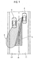
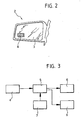
- a motor vehicle A has an external rear-view mirror 2, in the reflecting plate 3 of which there is incorporated an opto-electronic sensor consisting of a digital telecamera 4 made using CMOS technology.
- the telecamera 4 can be integrated in the body of the mirror or on its support fixed to the vehicle.
- the telecamera 4 has a field of vision defined by the area B in Figure 1, which increases considerably the driving safety, if it is taken into account that the field of vision of the rear-view mirror alone is the one indicated by the area C.
- the signals emitted by the sensor 4 are sent to an electronic processing circuit 5, which sees to processing said signals in a completely digital way.
- the circuit 5 carries out a series of sensing operations in a way similar to what has already been obtained by known devices, such as for example the measurement of the distance between the vehicle A and a vehicle that is following D, during overtaking.
- the electronic processing means 5 are moreover provided for detecting the lateral distance existing between the motor vehicle A and the adjacent side M of the lane L1 on which the motor vehicle A is travelling.
- the electronic processing means 5 are provided for activating an optical-alarm signaller 6, provided on the dashboard of the vehicle or in the proximity of the external rear-view mirror, outside or inside the vehicle, in the case where the processing means 5 detect approach of the motor vehicle A to the edge M of the lane L1 in concomitance with approach of a vehicle that is following D along the lane L2 onto which the motor vehicle A intends to shift its position.
- the electronic processing means 5 detect also the activation, by the driver, of the control member 7, which causes switching-on of the direction indicators, or else an excessive approach to the edge of the lane (both phenomena constituting definite signs of the intention of the driver to change lane), the electronic processing means 5 control a further alarm signaller 8, this time of an acoustic type.
- the electronic processing means can be programmed in various ways. For example, it is possible to envisage that a first alarm signal will be generated when the lateral distance between the motor vehicle and the edge M of the lane drops below a pre-determined value. Or else, it would be possible to envisage that said signal will be generated as soon as a lateral approach of the motor vehicle to the edge of the lane is detected, irrespective of the distance existing from said edge. Yet again, it would be possible to envisage that the aforesaid function will exist only in the case of an approach towards the left-hand side of the lane, or else towards either side.
- CMOS complementary metal-oxide-semiconductor
- the digital telecamera is a colour camera, in so far as the use of colour improves the robustness of the signal and the capacity for operating correctly in all environmental conditions, as well as eliminating disturbances due to possible shadows of the vehicle itself or of other surrounding objects.
- the sensor Given its contained overall dimensions, the sensor can be integrated directly in the glass of the rear-view mirror or, in any case, in the body of the mirror or in its supporting base.
Abstract
Description
- Figure 1 is a view from above of a road traversed by a motor vehicle equipped with the system according to the invention,
- Figure 2 is a schematic front view of an external rear-view mirror of a motor vehicle equipped with the sensor means forming part of the invention, and
- Figure 3 is a block diagram of the system according to the invention.
Claims (7)
- A method for assisting the driver of a motor vehicle in a lane-change manoeuvre, by signalling the emergency condition generated by the approach of another motor vehicle along the same lane onto which the first motor vehicle is moving,
method including:providing passive digital opto-electronic sensor means (4), of the CMOS type, on the external rear-view mirror (2) of the first motor vehicle,processing the signals emitted by said sensor means (4) for the position of the motor vehicle (A) with respect to the side (M) closest to the lane (L1) on which it is travelling,processing the signals emitted by said sensor means (4) for detecting when a vehicle (D) that is following is approaching on the lane (L2) adjacent to said side (M) of the lane (L1) on which the first motor vehicle (A) is travelling, andgenerating an alarm signal (6, 8) when approach of the vehicle (D) that is following in concomitance with a lateral approach of the first vehicle (A) towards the aforesaid adjacent lane (L2) is detected,wherein the alarm signal is an optical signal,characterized in that the alarm signal becomes an acoustic signal when an activation of the direction indicator by the driver is detected, which is interpreted as a definite sign of the intention of the driver to change lane. - The method according to Claim 1, characterized in that a further alarm signal is generated when an excessive approach to the edge of the lane is detected, in the absence of activation of the direction indicator, as warning of unintentional exit from the lane.
- A system for assisting the driver of a motor vehicle (A) in a lane-change manoeuvre, by signalling the emergency condition generated by the approach of another motor vehicle (D) along the same lane (L2) onto which the first motor vehicle (A) is moving, said system including :wherein said alarm signal is an optical signal,passive digital opto-electronic sensor means (4), of the CMOS type, provided on the external rear-view mirror (2) of the first motor vehicle (A),electronic processing means (5) for processing the signals emitted by said sensor means (4) with the aim of detecting the position of the motor vehicle with respect to the side (M) closest to the lane (L1) on which it is travelling,said electronic processing means (5) being designed for processing the signals emitted by said sensor means (4) for detecting when a motor vehicle that is following (D) is approaching on the lane (L2) adjacent to said side (M) of the lane (L1) on which the first motor vehicle (A) is travelling, andsaid electronic processing means being designed for generating an alarm signal when they detect an approach of the motor vehicle that is following (D) in concomitance with a lateral approach of the first motor vehicle (A) to said adjacent lane,
characterized in that said alarm signal becomes also an acoustic signal when the electronic processing means (5) detect activation of the control member (7) of the direction indicator of the motor vehicle, which is interpreted as a definite sign of the intention of the driver to change lane. - The system according to Claim 3, characterized in that a further alarm signal is generated when an excessive approach to the edge of the lane is detected, in the absence of activation of the direction indicator, as warning of unintentional exit from the lane.
- The system according to Claim 3, characterized in that said sensor means consist of a digital telecamera (4).
- The system according to Claim 5, characterized in that the aforesaid digital telecamera is a colour camera.
- The system according to Claim 3, characterized in that the aforesaid processing means are of a completely digital type.
Applications Claiming Priority (2)
| Application Number | Priority Date | Filing Date | Title |
|---|---|---|---|
| IT2001TO001057A ITTO20011057A1 (en) | 2001-11-07 | 2001-11-07 | ,, METHOD AND SYSTEM TO ASSIST THE DRIVER OF A MOTOR VEHICLE IN A CHANGE OF CORSIA MANEUVER ,,. |
| ITTO20011057 | 2001-11-07 |
Publications (3)
| Publication Number | Publication Date |
|---|---|
| EP1312506A2 EP1312506A2 (en) | 2003-05-21 |
| EP1312506A3 EP1312506A3 (en) | 2004-05-06 |
| EP1312506B1 true EP1312506B1 (en) | 2005-12-14 |
Family
ID=11459291
Family Applications (1)
| Application Number | Title | Priority Date | Filing Date |
|---|---|---|---|
| EP02024147A Expired - Lifetime EP1312506B1 (en) | 2001-11-07 | 2002-10-30 | A method and system for assisting the driver of a motor vehicle in a lane-change manoeuvre |
Country Status (5)
| Country | Link |
|---|---|
| EP (1) | EP1312506B1 (en) |
| AT (1) | ATE312730T1 (en) |
| DE (1) | DE60207965T2 (en) |
| ES (1) | ES2253485T3 (en) |
| IT (1) | ITTO20011057A1 (en) |
Cited By (3)
| Publication number | Priority date | Publication date | Assignee | Title |
|---|---|---|---|---|
| WO2012089357A2 (en) | 2010-12-29 | 2012-07-05 | Siemens S.A.S. | System and method for active lane-changing assistance for a motor vehicle |
| EP2899083A2 (en) | 2014-01-28 | 2015-07-29 | MAN Truck & Bus AG | Method and driver assistance system for assisting a driver of a motor vehicle when changing lanes |
| US9251709B2 (en) | 2013-11-25 | 2016-02-02 | Nissan North America, Inc. | Lateral vehicle contact warning system |
Families Citing this family (6)
| Publication number | Priority date | Publication date | Assignee | Title |
|---|---|---|---|---|
| GB0314156D0 (en) * | 2003-06-18 | 2003-07-23 | Dsine Technology Ltd | Proximity sensing system |
| DE10342528A1 (en) * | 2003-09-12 | 2005-04-14 | Robert Bosch Gmbh | Method and device for driver assistance |
| KR101279220B1 (en) * | 2005-03-03 | 2013-06-26 | 콘티넨탈 테베스 아게 운트 코. 오하게 | Method and device for avoiding a collision as a vehicle is changing lanes |
| ITMI20050788A1 (en) | 2005-05-02 | 2006-11-03 | Iveco Spa | RIDING AID SYSTEM TO SUPPORT THE CORSA MAINTENANCE TO ASSIST THE CHANGE OF SLIDES AND MONITOR THE STATE OF THE DRIVER OF A VEHICLE |
| EP2119617A1 (en) | 2008-05-12 | 2009-11-18 | IVECO S.p.A. | Vehicle driving aid system for lane changing assistance |
| DE102011018159A1 (en) * | 2011-04-19 | 2012-10-25 | GM Global Technology Operations LLC (n. d. Gesetzen des Staates Delaware) | Device and method for driver assistance |
Family Cites Families (12)
| Publication number | Priority date | Publication date | Assignee | Title |
|---|---|---|---|---|
| US5001558A (en) * | 1985-06-11 | 1991-03-19 | General Motors Corporation | Night vision system with color video camera |
| DE3902852A1 (en) | 1989-02-01 | 1990-08-02 | Hohe Kg | EXTERIOR MIRROR FOR A MOTOR VEHICLE |
| US4987357A (en) * | 1989-12-18 | 1991-01-22 | General Motors Corporation | Adaptive motor vehicle cruise control |
| DE4005444A1 (en) | 1990-02-21 | 1991-08-22 | Bayerische Motoren Werke Ag | METHOD AND DEVICE FOR SUPPORTING A DRIVER FOR A ROAD TRACK CHANGE |
| FR2661268B1 (en) | 1990-04-20 | 1992-08-14 | Renault | DEVICE FOR VISUALIZING OBSTACLES, ESPECIALLY FOR A VEHICLE. |
| IT1256956B (en) | 1992-10-05 | 1995-12-27 | Gilardini Spa | DEVICE TO DETECT RELATIVE POSITIONS BETWEEN VEHICLES, MAINLY IN ANTI-COLLISION FUNCTION. |
| DE19507957C1 (en) * | 1995-03-07 | 1996-09-12 | Daimler Benz Ag | Vehicle with optical scanning device for a side lane area |
| DE19801884A1 (en) * | 1998-01-20 | 1999-07-22 | Mannesmann Vdo Ag | CCTV monitoring system for blind spots around motor vehicle |
| JPH11321495A (en) * | 1998-05-08 | 1999-11-24 | Yazaki Corp | Rear side watching device |
| JP3298851B2 (en) * | 1999-08-18 | 2002-07-08 | 松下電器産業株式会社 | Multi-function vehicle camera system and image display method of multi-function vehicle camera |
| ES2158827B1 (en) * | 2000-02-18 | 2002-03-16 | Fico Mirrors Sa | DEVICE FOR DETECTION OF PRESENCE OF OBJECTS. |
| AU2001259640A1 (en) * | 2000-05-08 | 2001-11-20 | Automotive Technologies International, Inc. | Vehicular blind spot identification and monitoring system |
-
2001
- 2001-11-07 IT IT2001TO001057A patent/ITTO20011057A1/en unknown
-
2002
- 2002-10-30 EP EP02024147A patent/EP1312506B1/en not_active Expired - Lifetime
- 2002-10-30 DE DE60207965T patent/DE60207965T2/en not_active Expired - Lifetime
- 2002-10-30 AT AT02024147T patent/ATE312730T1/en not_active IP Right Cessation
- 2002-10-30 ES ES02024147T patent/ES2253485T3/en not_active Expired - Lifetime
Cited By (4)
| Publication number | Priority date | Publication date | Assignee | Title |
|---|---|---|---|---|
| WO2012089357A2 (en) | 2010-12-29 | 2012-07-05 | Siemens S.A.S. | System and method for active lane-changing assistance for a motor vehicle |
| US9251709B2 (en) | 2013-11-25 | 2016-02-02 | Nissan North America, Inc. | Lateral vehicle contact warning system |
| EP2899083A2 (en) | 2014-01-28 | 2015-07-29 | MAN Truck & Bus AG | Method and driver assistance system for assisting a driver of a motor vehicle when changing lanes |
| DE102014001115A1 (en) | 2014-01-28 | 2015-07-30 | Man Truck & Bus Ag | Method and driver assistance system for assisting a driver of a motor vehicle during a lane change |
Also Published As
| Publication number | Publication date |
|---|---|
| ITTO20011057A1 (en) | 2003-05-07 |
| DE60207965D1 (en) | 2006-01-19 |
| EP1312506A3 (en) | 2004-05-06 |
| ES2253485T3 (en) | 2006-06-01 |
| ATE312730T1 (en) | 2005-12-15 |
| EP1312506A2 (en) | 2003-05-21 |
| DE60207965T2 (en) | 2006-06-29 |
Similar Documents
| Publication | Publication Date | Title |
|---|---|---|
| CN106331446B (en) | Camera device and in-vehicle system | |
| KR101737737B1 (en) | Hud integrated cluster system for vehicle camera | |
| EP0591743A1 (en) | Device for detecting relative positions between vehicles, principally for anti-collision purposes | |
| EP1129904B1 (en) | Monitoring device of blind zones around vehicles | |
| US7123168B2 (en) | Driving separation distance indicator | |
| EP2653346B1 (en) | Vehicle safety illumination arrangement and method | |
| CN104175954A (en) | Vehicle blind area monitoring and alarming system | |
| JP2007114193A (en) | On-board optical sensor device for assisting driving and/or for automatically operating system mounted on automobile | |
| JPH08175228A (en) | Driving support device | |
| EP1312506B1 (en) | A method and system for assisting the driver of a motor vehicle in a lane-change manoeuvre | |
| WO2011136472A2 (en) | Alarm system for preventing lateral collisions, replacing the side-view mirrors of a vehicle | |
| US20040212676A1 (en) | Optical detection system for vehicles | |
| US20210188163A1 (en) | U-turn signal indicator | |
| CN210526396U (en) | Intelligent auxiliary driving system | |
| JP4375153B2 (en) | Vehicle display device | |
| JPH10989A (en) | Information display system | |
| JP2001008195A (en) | Device for monitoring rear part of vehicle | |
| Mimuro et al. | Functions and devices of Mitsubishi active safety ASV | |
| US20060103509A1 (en) | Alarm system for a vehicle | |
| GB2353167A (en) | Vehicle mounted imaging system | |
| CN216734066U (en) | Informing device and vehicle | |
| KR102251573B1 (en) | Vehicle-side multi-camera device and vehicle surroundings information providing device | |
| JP2005182455A (en) | Communication system between vehicles | |
| JP7194890B2 (en) | car mirror device | |
| JP2006277376A (en) | Traffic violation warning device and system |
Legal Events
| Date | Code | Title | Description |
|---|---|---|---|
| PUAI | Public reference made under article 153(3) epc to a published international application that has entered the european phase |
Free format text: ORIGINAL CODE: 0009012 |
|
| AK | Designated contracting states |
Designated state(s): AT BE BG CH CY CZ DE DK EE ES FI FR GB GR IE IT LI LU MC NL PT SE SK TR |
|
| AX | Request for extension of the european patent |
Extension state: AL LT LV MK RO SI |
|
| PUAL | Search report despatched |
Free format text: ORIGINAL CODE: 0009013 |
|
| AK | Designated contracting states |
Kind code of ref document: A3 Designated state(s): AT BE BG CH CY CZ DE DK EE ES FI FR GB GR IE IT LI LU MC NL PT SE SK TR |
|
| AX | Request for extension of the european patent |
Extension state: AL LT LV MK RO SI |
|
| RIC1 | Information provided on ipc code assigned before grant |
Ipc: 7G 01S 13/93 B Ipc: 7B 60Q 1/52 A Ipc: 7G 01S 11/12 B |
|
| 17P | Request for examination filed |
Effective date: 20040719 |
|
| 17Q | First examination report despatched |
Effective date: 20040830 |
|
| AKX | Designation fees paid |
Designated state(s): AT BE BG CH CY CZ DE DK EE ES FI FR GB GR IE IT LI LU MC NL PT SE SK TR |
|
| GRAP | Despatch of communication of intention to grant a patent |
Free format text: ORIGINAL CODE: EPIDOSNIGR1 |
|
| GRAS | Grant fee paid |
Free format text: ORIGINAL CODE: EPIDOSNIGR3 |
|
| GRAA | (expected) grant |
Free format text: ORIGINAL CODE: 0009210 |
|
| AK | Designated contracting states |
Kind code of ref document: B1 Designated state(s): AT BE BG CH CY CZ DE DK EE ES FI FR GB GR IE IT LI LU MC NL PT SE SK TR |
|
| PG25 | Lapsed in a contracting state [announced via postgrant information from national office to epo] |
Ref country code: SK Free format text: LAPSE BECAUSE OF FAILURE TO SUBMIT A TRANSLATION OF THE DESCRIPTION OR TO PAY THE FEE WITHIN THE PRESCRIBED TIME-LIMIT Effective date: 20051214 Ref country code: FI Free format text: LAPSE BECAUSE OF FAILURE TO SUBMIT A TRANSLATION OF THE DESCRIPTION OR TO PAY THE FEE WITHIN THE PRESCRIBED TIME-LIMIT Effective date: 20051214 Ref country code: AT Free format text: LAPSE BECAUSE OF FAILURE TO SUBMIT A TRANSLATION OF THE DESCRIPTION OR TO PAY THE FEE WITHIN THE PRESCRIBED TIME-LIMIT Effective date: 20051214 Ref country code: LI Free format text: LAPSE BECAUSE OF FAILURE TO SUBMIT A TRANSLATION OF THE DESCRIPTION OR TO PAY THE FEE WITHIN THE PRESCRIBED TIME-LIMIT Effective date: 20051214 Ref country code: CH Free format text: LAPSE BECAUSE OF FAILURE TO SUBMIT A TRANSLATION OF THE DESCRIPTION OR TO PAY THE FEE WITHIN THE PRESCRIBED TIME-LIMIT Effective date: 20051214 Ref country code: CZ Free format text: LAPSE BECAUSE OF FAILURE TO SUBMIT A TRANSLATION OF THE DESCRIPTION OR TO PAY THE FEE WITHIN THE PRESCRIBED TIME-LIMIT Effective date: 20051214 Ref country code: BE Free format text: LAPSE BECAUSE OF FAILURE TO SUBMIT A TRANSLATION OF THE DESCRIPTION OR TO PAY THE FEE WITHIN THE PRESCRIBED TIME-LIMIT Effective date: 20051214 Ref country code: NL Free format text: LAPSE BECAUSE OF FAILURE TO SUBMIT A TRANSLATION OF THE DESCRIPTION OR TO PAY THE FEE WITHIN THE PRESCRIBED TIME-LIMIT Effective date: 20051214 |
|
| REG | Reference to a national code |
Ref country code: GB Ref legal event code: FG4D |
|
| REG | Reference to a national code |
Ref country code: CH Ref legal event code: EP |
|
| REG | Reference to a national code |
Ref country code: SE Ref legal event code: TRGR |
|
| REG | Reference to a national code |
Ref country code: IE Ref legal event code: FG4D |
|
| REF | Corresponds to: |
Ref document number: 60207965 Country of ref document: DE Date of ref document: 20060119 Kind code of ref document: P |
|
| PG25 | Lapsed in a contracting state [announced via postgrant information from national office to epo] |
Ref country code: GR Free format text: LAPSE BECAUSE OF FAILURE TO SUBMIT A TRANSLATION OF THE DESCRIPTION OR TO PAY THE FEE WITHIN THE PRESCRIBED TIME-LIMIT Effective date: 20060314 Ref country code: BG Free format text: LAPSE BECAUSE OF FAILURE TO SUBMIT A TRANSLATION OF THE DESCRIPTION OR TO PAY THE FEE WITHIN THE PRESCRIBED TIME-LIMIT Effective date: 20060314 Ref country code: DK Free format text: LAPSE BECAUSE OF FAILURE TO SUBMIT A TRANSLATION OF THE DESCRIPTION OR TO PAY THE FEE WITHIN THE PRESCRIBED TIME-LIMIT Effective date: 20060314 |
|
| PG25 | Lapsed in a contracting state [announced via postgrant information from national office to epo] |
Ref country code: PT Free format text: LAPSE BECAUSE OF FAILURE TO SUBMIT A TRANSLATION OF THE DESCRIPTION OR TO PAY THE FEE WITHIN THE PRESCRIBED TIME-LIMIT Effective date: 20060515 |
|
| NLV1 | Nl: lapsed or annulled due to failure to fulfill the requirements of art. 29p and 29m of the patents act | ||
| REG | Reference to a national code |
Ref country code: ES Ref legal event code: FG2A Ref document number: 2253485 Country of ref document: ES Kind code of ref document: T3 |
|
| REG | Reference to a national code |
Ref country code: CH Ref legal event code: PL |
|
| ET | Fr: translation filed | ||
| PLBE | No opposition filed within time limit |
Free format text: ORIGINAL CODE: 0009261 |
|
| STAA | Information on the status of an ep patent application or granted ep patent |
Free format text: STATUS: NO OPPOSITION FILED WITHIN TIME LIMIT |
|
| PG25 | Lapsed in a contracting state [announced via postgrant information from national office to epo] |
Ref country code: IE Free format text: LAPSE BECAUSE OF NON-PAYMENT OF DUE FEES Effective date: 20061030 |
|
| PG25 | Lapsed in a contracting state [announced via postgrant information from national office to epo] |
Ref country code: MC Free format text: LAPSE BECAUSE OF NON-PAYMENT OF DUE FEES Effective date: 20061031 |
|
| 26N | No opposition filed |
Effective date: 20060915 |
|
| REG | Reference to a national code |
Ref country code: IE Ref legal event code: MM4A |
|
| PG25 | Lapsed in a contracting state [announced via postgrant information from national office to epo] |
Ref country code: EE Free format text: LAPSE BECAUSE OF FAILURE TO SUBMIT A TRANSLATION OF THE DESCRIPTION OR TO PAY THE FEE WITHIN THE PRESCRIBED TIME-LIMIT Effective date: 20051214 |
|
| PG25 | Lapsed in a contracting state [announced via postgrant information from national office to epo] |
Ref country code: TR Free format text: LAPSE BECAUSE OF FAILURE TO SUBMIT A TRANSLATION OF THE DESCRIPTION OR TO PAY THE FEE WITHIN THE PRESCRIBED TIME-LIMIT Effective date: 20051214 Ref country code: LU Free format text: LAPSE BECAUSE OF NON-PAYMENT OF DUE FEES Effective date: 20061030 |
|
| PG25 | Lapsed in a contracting state [announced via postgrant information from national office to epo] |
Ref country code: CY Free format text: LAPSE BECAUSE OF FAILURE TO SUBMIT A TRANSLATION OF THE DESCRIPTION OR TO PAY THE FEE WITHIN THE PRESCRIBED TIME-LIMIT Effective date: 20051214 |
|
| REG | Reference to a national code |
Ref country code: FR Ref legal event code: PLFP Year of fee payment: 15 |
|
| REG | Reference to a national code |
Ref country code: FR Ref legal event code: PLFP Year of fee payment: 16 |
|
| REG | Reference to a national code |
Ref country code: FR Ref legal event code: PLFP Year of fee payment: 17 |
|
| PGFP | Annual fee paid to national office [announced via postgrant information from national office to epo] |
Ref country code: SE Payment date: 20191029 Year of fee payment: 18 |
|
| PGFP | Annual fee paid to national office [announced via postgrant information from national office to epo] |
Ref country code: IT Payment date: 20191008 Year of fee payment: 18 Ref country code: FR Payment date: 20191029 Year of fee payment: 18 Ref country code: ES Payment date: 20191125 Year of fee payment: 18 |
|
| PGFP | Annual fee paid to national office [announced via postgrant information from national office to epo] |
Ref country code: DE Payment date: 20191227 Year of fee payment: 18 Ref country code: GB Payment date: 20191029 Year of fee payment: 18 |
|
| REG | Reference to a national code |
Ref country code: DE Ref legal event code: R119 Ref document number: 60207965 Country of ref document: DE |
|
| REG | Reference to a national code |
Ref country code: SE Ref legal event code: EUG |
|
| GBPC | Gb: european patent ceased through non-payment of renewal fee |
Effective date: 20201030 |
|
| PG25 | Lapsed in a contracting state [announced via postgrant information from national office to epo] |
Ref country code: FR Free format text: LAPSE BECAUSE OF NON-PAYMENT OF DUE FEES Effective date: 20201031 Ref country code: DE Free format text: LAPSE BECAUSE OF NON-PAYMENT OF DUE FEES Effective date: 20210501 |
|
| PG25 | Lapsed in a contracting state [announced via postgrant information from national office to epo] |
Ref country code: SE Free format text: LAPSE BECAUSE OF NON-PAYMENT OF DUE FEES Effective date: 20201031 Ref country code: GB Free format text: LAPSE BECAUSE OF NON-PAYMENT OF DUE FEES Effective date: 20201030 |
|
| PG25 | Lapsed in a contracting state [announced via postgrant information from national office to epo] |
Ref country code: IT Free format text: LAPSE BECAUSE OF NON-PAYMENT OF DUE FEES Effective date: 20201030 |
|
| REG | Reference to a national code |
Ref country code: ES Ref legal event code: FD2A Effective date: 20220128 |
|
| PG25 | Lapsed in a contracting state [announced via postgrant information from national office to epo] |
Ref country code: ES Free format text: LAPSE BECAUSE OF NON-PAYMENT OF DUE FEES Effective date: 20201031 |