EP1312439A1 - Machine tool with special configuration of drive line, guide surfaces and center of gravity of moving object - Google Patents
Machine tool with special configuration of drive line, guide surfaces and center of gravity of moving object Download PDFInfo
- Publication number
- EP1312439A1 EP1312439A1 EP02023008A EP02023008A EP1312439A1 EP 1312439 A1 EP1312439 A1 EP 1312439A1 EP 02023008 A EP02023008 A EP 02023008A EP 02023008 A EP02023008 A EP 02023008A EP 1312439 A1 EP1312439 A1 EP 1312439A1
- Authority
- EP
- European Patent Office
- Prior art keywords
- center
- gravity
- moving object
- table body
- drive line
- Prior art date
- Legal status (The legal status is an assumption and is not a legal conclusion. Google has not performed a legal analysis and makes no representation as to the accuracy of the status listed.)
- Withdrawn
Links
Images


Classifications
-
- B—PERFORMING OPERATIONS; TRANSPORTING
- B23—MACHINE TOOLS; METAL-WORKING NOT OTHERWISE PROVIDED FOR
- B23Q—DETAILS, COMPONENTS, OR ACCESSORIES FOR MACHINE TOOLS, e.g. ARRANGEMENTS FOR COPYING OR CONTROLLING; MACHINE TOOLS IN GENERAL CHARACTERISED BY THE CONSTRUCTION OF PARTICULAR DETAILS OR COMPONENTS; COMBINATIONS OR ASSOCIATIONS OF METAL-WORKING MACHINES, NOT DIRECTED TO A PARTICULAR RESULT
- B23Q5/00—Driving or feeding mechanisms; Control arrangements therefor
-
- B—PERFORMING OPERATIONS; TRANSPORTING
- B23—MACHINE TOOLS; METAL-WORKING NOT OTHERWISE PROVIDED FOR
- B23Q—DETAILS, COMPONENTS, OR ACCESSORIES FOR MACHINE TOOLS, e.g. ARRANGEMENTS FOR COPYING OR CONTROLLING; MACHINE TOOLS IN GENERAL CHARACTERISED BY THE CONSTRUCTION OF PARTICULAR DETAILS OR COMPONENTS; COMBINATIONS OR ASSOCIATIONS OF METAL-WORKING MACHINES, NOT DIRECTED TO A PARTICULAR RESULT
- B23Q11/00—Accessories fitted to machine tools for keeping tools or parts of the machine in good working condition or for cooling work; Safety devices specially combined with or arranged in, or specially adapted for use in connection with, machine tools
- B23Q11/0032—Arrangements for preventing or isolating vibrations in parts of the machine
-
- B—PERFORMING OPERATIONS; TRANSPORTING
- B23—MACHINE TOOLS; METAL-WORKING NOT OTHERWISE PROVIDED FOR
- B23Q—DETAILS, COMPONENTS, OR ACCESSORIES FOR MACHINE TOOLS, e.g. ARRANGEMENTS FOR COPYING OR CONTROLLING; MACHINE TOOLS IN GENERAL CHARACTERISED BY THE CONSTRUCTION OF PARTICULAR DETAILS OR COMPONENTS; COMBINATIONS OR ASSOCIATIONS OF METAL-WORKING MACHINES, NOT DIRECTED TO A PARTICULAR RESULT
- B23Q1/00—Members which are comprised in the general build-up of a form of machine, particularly relatively large fixed members
- B23Q1/01—Frames, beds, pillars or like members; Arrangement of ways
- B23Q1/017—Arrangements of ways
-
- B—PERFORMING OPERATIONS; TRANSPORTING
- B23—MACHINE TOOLS; METAL-WORKING NOT OTHERWISE PROVIDED FOR
- B23Q—DETAILS, COMPONENTS, OR ACCESSORIES FOR MACHINE TOOLS, e.g. ARRANGEMENTS FOR COPYING OR CONTROLLING; MACHINE TOOLS IN GENERAL CHARACTERISED BY THE CONSTRUCTION OF PARTICULAR DETAILS OR COMPONENTS; COMBINATIONS OR ASSOCIATIONS OF METAL-WORKING MACHINES, NOT DIRECTED TO A PARTICULAR RESULT
- B23Q5/00—Driving or feeding mechanisms; Control arrangements therefor
- B23Q5/22—Feeding members carrying tools or work
- B23Q5/34—Feeding other members supporting tools or work, e.g. saddles, tool-slides, through mechanical transmission
- B23Q5/38—Feeding other members supporting tools or work, e.g. saddles, tool-slides, through mechanical transmission feeding continuously
- B23Q5/40—Feeding other members supporting tools or work, e.g. saddles, tool-slides, through mechanical transmission feeding continuously by feed shaft, e.g. lead screw
-
- Y—GENERAL TAGGING OF NEW TECHNOLOGICAL DEVELOPMENTS; GENERAL TAGGING OF CROSS-SECTIONAL TECHNOLOGIES SPANNING OVER SEVERAL SECTIONS OF THE IPC; TECHNICAL SUBJECTS COVERED BY FORMER USPC CROSS-REFERENCE ART COLLECTIONS [XRACs] AND DIGESTS
- Y10—TECHNICAL SUBJECTS COVERED BY FORMER USPC
- Y10T—TECHNICAL SUBJECTS COVERED BY FORMER US CLASSIFICATION
- Y10T409/00—Gear cutting, milling, or planing
- Y10T409/30—Milling
- Y10T409/304536—Milling including means to infeed work to cutter
- Y10T409/305544—Milling including means to infeed work to cutter with work holder
- Y10T409/305656—Milling including means to infeed work to cutter with work holder including means to support work for rotation during operation
- Y10T409/305768—Milling including means to infeed work to cutter with work holder including means to support work for rotation during operation with linear movement of work
-
- Y—GENERAL TAGGING OF NEW TECHNOLOGICAL DEVELOPMENTS; GENERAL TAGGING OF CROSS-SECTIONAL TECHNOLOGIES SPANNING OVER SEVERAL SECTIONS OF THE IPC; TECHNICAL SUBJECTS COVERED BY FORMER USPC CROSS-REFERENCE ART COLLECTIONS [XRACs] AND DIGESTS
- Y10—TECHNICAL SUBJECTS COVERED BY FORMER USPC
- Y10T—TECHNICAL SUBJECTS COVERED BY FORMER US CLASSIFICATION
- Y10T409/00—Gear cutting, milling, or planing
- Y10T409/30—Milling
- Y10T409/304536—Milling including means to infeed work to cutter
- Y10T409/305544—Milling including means to infeed work to cutter with work holder
- Y10T409/305656—Milling including means to infeed work to cutter with work holder including means to support work for rotation during operation
- Y10T409/305824—Milling including means to infeed work to cutter with work holder including means to support work for rotation during operation with angular movement of work
-
- Y—GENERAL TAGGING OF NEW TECHNOLOGICAL DEVELOPMENTS; GENERAL TAGGING OF CROSS-SECTIONAL TECHNOLOGIES SPANNING OVER SEVERAL SECTIONS OF THE IPC; TECHNICAL SUBJECTS COVERED BY FORMER USPC CROSS-REFERENCE ART COLLECTIONS [XRACs] AND DIGESTS
- Y10—TECHNICAL SUBJECTS COVERED BY FORMER USPC
- Y10T—TECHNICAL SUBJECTS COVERED BY FORMER US CLASSIFICATION
- Y10T409/00—Gear cutting, milling, or planing
- Y10T409/30—Milling
- Y10T409/30868—Work support
-
- Y—GENERAL TAGGING OF NEW TECHNOLOGICAL DEVELOPMENTS; GENERAL TAGGING OF CROSS-SECTIONAL TECHNOLOGIES SPANNING OVER SEVERAL SECTIONS OF THE IPC; TECHNICAL SUBJECTS COVERED BY FORMER USPC CROSS-REFERENCE ART COLLECTIONS [XRACs] AND DIGESTS
- Y10—TECHNICAL SUBJECTS COVERED BY FORMER USPC
- Y10T—TECHNICAL SUBJECTS COVERED BY FORMER US CLASSIFICATION
- Y10T409/00—Gear cutting, milling, or planing
- Y10T409/30—Milling
- Y10T409/309576—Machine frame
- Y10T409/309912—Machine frame including relatively movable components and means to relatively immobilize these components
-
- Y—GENERAL TAGGING OF NEW TECHNOLOGICAL DEVELOPMENTS; GENERAL TAGGING OF CROSS-SECTIONAL TECHNOLOGIES SPANNING OVER SEVERAL SECTIONS OF THE IPC; TECHNICAL SUBJECTS COVERED BY FORMER USPC CROSS-REFERENCE ART COLLECTIONS [XRACs] AND DIGESTS
- Y10—TECHNICAL SUBJECTS COVERED BY FORMER USPC
- Y10T—TECHNICAL SUBJECTS COVERED BY FORMER US CLASSIFICATION
- Y10T483/00—Tool changing
- Y10T483/17—Tool changing including machine tool or component
- Y10T483/1733—Rotary spindle machine tool [e.g., milling machine, boring, machine, grinding machine, etc.]
Definitions
- This invention relates to a machine tool, such as a machining center, which performs machining while moving a work table and a main spindle for a tool relative to each other.
- a moving object such as a table or a spindle head
- a structure such as a bed or a frame
- a drive line which causes a relative movement in the direction of the guide surface
- the positional relationship between the guide surface and the center of gravity of the moving object is not taken into account, and the center of gravity of the moving object and the guide surface are not in the same plane parallel to the direction of movement, but they are located at relatively remote positions.
- a flexural vibrating force which deforms the structure, is increased by the inertial force of the moving object and a reaction force generated in the structure by the drive line.
- vibrations are liable to occur.
- the present invention has been accomplished in light of the above-mentioned problems with the conventional machine tool. Its object is to provide a machine tool which can effectively suppress vibrations of a structure generated during movement of a moving object relative to the structure by a drive line, thereby shortening the machining time and increasing productivity.
- a machine tool comprising:
- vibrations of the structure which occur when the moving object is moved relative to the structure by the drive line, can be effectively suppressed, and the machining time can be shortened to increase productivity.
- the position of the center of gravity of the moving object, the guide surfaces, and the drive line may be installed in the same plane parallel to the direction of movement of the moving object. In this case, the effects of the present invention can be further enhanced.
- a connecting portion of the drive line connected to the moving object may be installed on a line passing the position of the center of gravity of the moving object and pointing in the direction of movement of the moving object. In this case, the conditions for installation of the drive line can be easily satisfied.
- a pair of the connecting portions of the drive line connected to the moving object may be provided, and a midpoint between the pair of the connecting portions may be consistent with the position of the center of gravity of the moving object. In this case, the conditions for installation of the drive line can be easily satisfied.
- FIG. 1 is a schematic perspective view of a horizontal machining center according to an embodiment of the present invention.
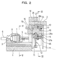
- FIG. 2 is a longitudinal sectional side view of the horizontal machining center.
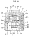
- FIG. 3 is a sectional view taken on line III-III of FIG. 2.
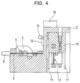
- FIG. 4 is a sectional view taken on line IV-IV of FIG. 3.
- FIG. 5 is a sectional view taken on line V-V of FIG. 2.
- FIG. 6 is an enlarged sectional view of a rack and pinion portion.
- FIGS. 7(a) and 7(b) are various schematic views of the present invention.
- FIG. 8 is an operational explanation drawing of X-axis counterweights for a spindle head.
- a gate-shaped column 2 is integrally erected at a rear portion of a bed (as a structure) 1 to constitute a horizontal machining center.
- a table body (as a moving object) 3 is disposed via right and left guide members 4 as a pair, each of which has a sliding or rolling guide surface, so as to be movable in a fore-and-aft direction (a Z-axis direction) by right and left ball screws 5 as a pair.
- the numeral 6 denotes a servo motor for the ball screw 5.
- a tilt table 8, which rotatably supports a rotary table 7 bearing a workpiece (not shown), is tiltably assembled to and supported on the table body 3.
- the right and left guide members 4 as a pair, the right and left ball screws 5 as a pair, and the table body 3 are provided such that the guide members 4, the ball screws 5 and the position of the center of gravity of the table body 3 are in the same plane parallel to the direction of movement of the table body 3, and that a midpoint between the right and left guide members 4 as a pair, and a midpoint between the right and left ball screws 5 as a pair are located at the position of the center of gravity of the table body 3.
- the guide surfaces of the right and left guide members 4 as a pair on the bed 1 are provided so as to be in a first plane A, which includes the position of the center of gravity, G, of the table body 3 and which is parallel to the direction of movement of the table body 3.
- the guide surfaces are also provided so as to be close to both sides of the table body 3, and such that the distances from the center of gravity, G, of the table body 3 to the respective guide surfaces are equal.
- nut portions 9 of the ball screws 5 beside the table body 3 are installed at a pair of positions in a second plane B which includes the position of the center of gravity, G, of the table body 3 and which is perpendicular to the axis of the table body 3 in the direction of movement, the midpoint between the pair of positions being located at the position of the center of gravity, G, of the table body 3.
- the nut portions 9 of the right and left ball screws 5 as a pair are also provided in the first plane A together with the guide members 4 and the center of gravity, G, of the table body 3.
- the nut portions 9 of the ball screws 5 may be provided at any positions in point symmetry about the position of the center of gravity, G, of the table body 3 in the second plane B.
- the nut portion 9 of the ball screw 5 beside the table body 3 may be installed on a straight line C including the position of the center of gravity, G, of the table body 3 and having a direction vector in the direction of movement of the table body 3.
- a box-shaped saddle (as a moving object) 10 is disposed via right and left, front and rear guide members (having sliding or rolling guide surfaces) 11 as two pairs so as to be movable in an up-and-down direction (Y-axis direction) by right and left ball screws 12 as a pair.
- nut portions (not shown) of the right and left ball screws 12 as a pair are installed at a pair of positions in a plane which includes the position of the center of gravity of the saddle 10 and which is perpendicular to the axis of the saddle 10 in the direction of its movement, the midpoint between the pair of positions being located at the position of the center of gravity of the saddle 10.
- the four guide members 11, when viewed in plan, are provided at positions which are on diagonals intersecting at the position of the center of gravity of the saddle 10, and which are at equal distances from the position of the center of gravity of the saddle 10.
- a spindle head (as a moving object) 15 is disposed via upper and lower, front and rear guide members (having sliding or rolling guide surfaces) 16 as two pairs so as to be movable in a right-and-left direction (X-axis direction) by front and rear ball screws 17 as a pair.
- nut portions (not shown) of the front and rear ball screws 17 as a pair are installed at a pair of positions in a plane which includes the position of the center of gravity of the spindle head 15 and which is perpendicular to the axis of the spindle head 15 in the direction of its movement, the midpoint between the pair of positions being located at the position of the center of gravity of the spindle head 15.
- the four guide members 16, when viewed from the side (see FIG. 2), are provided at positions which are on diagonals intersecting at the position of the center of gravity of the spindle head 15, and which are at equal distances from the position of the center of gravity of the spindle head 15.
- the numeral 18 denotes a tool magazine installed on an upper surface portion of the column 2
- the numeral 19 denotes a tool replacement arm installed on a front surface portion of the column 2.
- Y-axis counterweights 20 are provided on outer surfaces of right and left side walls of the column 2 via right and left, front and rear guide members 21 (see FIG. 1) as two pairs so as to be movable in a Y-axis direction.
- the Y-axis counterweights 20 can be moved in a direction opposite to the direction of movement of the saddle 10 by the engagement of pinions 22a and 22b rotatably supported by the right and left side walls with racks 23a and 23b engraved on the outer surfaces of right and left side walls of the saddle 10 and the inner surfaces of the Y-axis counterweights 20. That is, the Y-axis counterweights 20 achieve weight balance during movement of the saddle 10 in the Y-axis direction.
- X-axis counterweights 25 are provided on outer surfaces of upper and lower walls of the saddle 10 via concave guide portions 26, which are elongated in a right-and-left direction, so as to be movable in an X-axis direction.
- the X-axis counterweights 25 can be moved in a direction opposite to the direction of movement of the spindle head 15 by the engagement of pinions 27a and 27b rotatably supported by the upper and lower walls with racks 28a and 28b engraved on the upper and lower surfaces of the spindle head 15 and the inner surfaces of the X-axis counterweights 25.
- the pinions 27a and 27b are provided in a central portion in the right-and-left direction of the saddle 10.
- the mass of the X-axis counterweight 25 on each side of the spindle head 15 is set at a half of the mass of the spindle head 15, whereby when the spindle head 15 is moved in the X-axis direction (the right-and-left direction in the drawing) by a servo motor 29 via the ball screw 17, the passive negative phase motions of the X-axis counterweights 25 are obtained, giving the damper action that the vibrating force is canceled out.
- the position of the engagement of the racks 28a on the spindle head 15 and the racks 28b on the X-axis counterweights 25 with the pinions 27a and 27b is set, whereby the position of the center of gravity of the spindle head 15 in the X-axis direction is unchanged (constant), even when the spindle head 15 is moved in the X-axis direction.
- the pinions 22a, 22b and the pinions 27a, 27b are formed of helical gears and helical racks, as shown in FIG. 6.
- the pinion 27a or 27b is divided into two parts in the direction of its axis of rotation, and one of the parts is always urged inwardly by a coned disc spring 33 to be capable of eliminating a backlash due to the engagement of the gears.
- the positional control of the spindle head 15 during machining is exercised by the movement of the spindle head 15 per se in the X-axis direction and the movement of the saddle 10 in the Y-axis direction.
- the spindle head 15 and the saddle 10 are driven via the pair of ball screws 17 and the pair of ball screws 12 disposed at the positions in point symmetry about their centers of gravity, while the spindle head 15 and the saddle 10 are being guided by the two pairs of guide members 16 and 11 disposed at the positions in point symmetry about their centers of gravity.
- These actions decrease the inertial forces of the spindle head 15 and the saddle 10 at the start or stop of movement, and the reaction forces caused to the saddle 10 and column 2 in support of them due to the driving of the ball screws 17 and 12.
- the vibrating force is canceled out by the negative phase motions of the X-axis counterweights 25, and the position of the center of gravity in the X-axis direction is unchanged, as stated earlier.
- weight balance is achieved by the negative phase motions of the Y-axis counterweights 20, as described above.
- the flexural vibrating force which deforms the saddle 10 and the column 2
- vibrations during movement of the spindle head 15 in the X-axis direction and during movement of the saddle 10 in the Y-axis direction are effectively suppressed.
- the spindle head 15 moves in the X-axis direction, the position of its center of gravity is unchanged, so that during movement of the saddle 10 in the Y-axis direction, load imposed is always equal for the right and left ball screws 12 as a pair.
- the positional control of the workpiece on the rotary table 7 during machining is performed by the movement (feeding) of the table body 3 in the Z-axis direction, in addition to the rotation of the rotary table 7 and the tilting of the tilt table 8.
- the table body 3 is driven by the pair of guide members 4 and the pair of ball screws 5 disposed in the same plane as the center of gravity, G, of the table body 3 and at the positions spaced laterally equally from the center of gravity, G, as stated earlier.
- This action decreases the inertial force of the table body 3 at the start or stop of movement, and the reaction force caused to the bed 1 in support of the table body 3 due to the driving of the ball screws 5.
- the flexural vibrating force, which deforms the bed 1 is markedly decreased, and vibrations during movement of the table body 3 in the Z-axis direction are effectively suppressed.
- the machining time can be shorted to increase productivity. Furthermore, it is easy to exercise various types of control when the saddle 10 housing the spindle head 15 is moved within the column 2.
- the drive line is not limited to the ball screws and servo motors, but may be other means.
- the guide members may be linear guides, etc.
Abstract
Description
- The entire disclosure of Japanese Patent Application No. 2001-349811 filed on November 15, 2001 including specification, claims, drawings and summary is incorporated herein by reference in its entirety.
- This invention relates to a machine tool, such as a machining center, which performs machining while moving a work table and a main spindle for a tool relative to each other.
- In a machine tool, such as a machining center, a moving object, such as a table or a spindle head, is supported linearly movably on a structure, such as a bed or a frame, via a sliding or rolling guide surface, and is driven (relatively moved) by a drive line which causes a relative movement in the direction of the guide surface.
- In this type of machine tool, the positional relationship between the guide surface and the center of gravity of the moving object is not taken into account, and the center of gravity of the moving object and the guide surface are not in the same plane parallel to the direction of movement, but they are located at relatively remote positions. Thus, when the moving object begins or stops movement by the action of the drive line, a flexural vibrating force, which deforms the structure, is increased by the inertial force of the moving object and a reaction force generated in the structure by the drive line. As a result, vibrations are liable to occur.
- If machining is started before settlement of the vibrations, the surface roughness of a workpiece increases (namely, its machining precision decreases). Thus, it has been customary practice to slow down acceleration or deceleration when the moving object begins or stops movement; or to start machining after the vibrations settle. Hence, it has been impossible to shorten the machining time and thereby increase productivity.
- Techniques for achieving fast acceleration and deceleration in machine tools have been proposed, for example, by Japanese Unexamined Patent Publication No. 1996-318445 and Japanese Unexamined Patent Publication No. 1999-235631. The former technique uses a linear motor as a drive source in a box frame type machine tool. The latter technique gives movement, in a direction perpendicular to each of the moving directions of first and second slides of a main spindle, as movement of a work table, whereby a uniform feeding load is exerted on a pair of drive mechanisms for driving the first slide of the main spindle, no matter what position is taken by the main spindle for a tool which moves toward and away from a workpiece on the first slide. However, neither of these techniques takes into consideration the positional relationship between a pair of guide surfaces and the center of gravity of a moving object. Hence, the aforementioned problems remain unsolved.
- The present invention has been accomplished in light of the above-mentioned problems with the conventional machine tool. Its object is to provide a machine tool which can effectively suppress vibrations of a structure generated during movement of a moving object relative to the structure by a drive line, thereby shortening the machining time and increasing productivity.
- According to the present invention, there is provided a machine tool comprising:
- a moving object movable along guide surfaces provided in a structure; and
- a drive line for moving the moving object, and wherein
- the guide surfaces are provided at positions in point symmetry about a position of a center of gravity of the moving object, and
- the drive line is provided at a position consistent with the position of the center of gravity of the moving object, or at positions in point symmetry about the position of the center of gravity of the moving object.
-
- According to the machine tool of the present invention, vibrations of the structure, which occur when the moving object is moved relative to the structure by the drive line, can be effectively suppressed, and the machining time can be shortened to increase productivity.
- In the machine tool, the position of the center of gravity of the moving object, the guide surfaces, and the drive line may be installed in the same plane parallel to the direction of movement of the moving object. In this case, the effects of the present invention can be further enhanced.
- In the machine tool, a connecting portion of the drive line connected to the moving object may be installed on a line passing the position of the center of gravity of the moving object and pointing in the direction of movement of the moving object. In this case, the conditions for installation of the drive line can be easily satisfied.
- In the machine tool, a pair of the connecting portions of the drive line connected to the moving object may be provided, and a midpoint between the pair of the connecting portions may be consistent with the position of the center of gravity of the moving object. In this case, the conditions for installation of the drive line can be easily satisfied.
- In the machine tool, four of the guide surfaces may be provided. In this case, the effects of the present invention can be further enhanced, and the conditions for installation of guide members can be easily satisfied.
- The present invention will become more fully understood from the detailed description given hereinbelow and the accompanying drawings which are given by way of illustration only, and thus are not limitative of the present invention, and wherein:
- FIG. 1 is a schematic perspective view of a horizontal machining center according to an embodiment of the present invention;
- FIG. 2 is a longitudinal sectional side view of the horizontal machining center;
- FIG. 3 is a sectional view taken on line III-III of FIG. 2;
- FIG. 4 is a sectional view taken on line IV-IV of FIG. 3;
- FIG. 5 is a sectional view taken on line V-V of FIG. 2;
- FIG. 6 is an enlarged sectional view of a rack and pinion portion;
- FIGS. 7(a) and 7(b) are various schematic views of the present invention; and
- FIG. 8 is an operational explanation drawing of X-axis counterweights for a spindle head.
-
- A machine tool according to the present invention will now be described in detail by an embodiment with reference to the accompanying drawings, which in no way limit the invention.
- FIG. 1 is a schematic perspective view of a horizontal machining center according to an embodiment of the present invention. FIG. 2 is a longitudinal sectional side view of the horizontal machining center. FIG. 3 is a sectional view taken on line III-III of FIG. 2. FIG. 4 is a sectional view taken on line IV-IV of FIG. 3. FIG. 5 is a sectional view taken on line V-V of FIG. 2. FIG. 6 is an enlarged sectional view of a rack and pinion portion. FIGS. 7(a) and 7(b) are various schematic views of the present invention. FIG. 8 is an operational explanation drawing of X-axis counterweights for a spindle head.
- As shown in FIGS. 1 to 5, a gate-
shaped column 2 is integrally erected at a rear portion of a bed (as a structure) 1 to constitute a horizontal machining center. On thebed 1, a table body (as a moving object) 3 is disposed via right andleft guide members 4 as a pair, each of which has a sliding or rolling guide surface, so as to be movable in a fore-and-aft direction (a Z-axis direction) by right andleft ball screws 5 as a pair. In the drawings, thenumeral 6 denotes a servo motor for theball screw 5. A tilt table 8, which rotatably supports a rotary table 7 bearing a workpiece (not shown), is tiltably assembled to and supported on thetable body 3. - In the present embodiment, the right and
left guide members 4 as a pair, the right andleft ball screws 5 as a pair, and thetable body 3 are provided such that theguide members 4, theball screws 5 and the position of the center of gravity of thetable body 3 are in the same plane parallel to the direction of movement of thetable body 3, and that a midpoint between the right andleft guide members 4 as a pair, and a midpoint between the right andleft ball screws 5 as a pair are located at the position of the center of gravity of thetable body 3. - That is, as shown in FIG. 7(b), the guide surfaces of the right and
left guide members 4 as a pair on thebed 1 are provided so as to be in a first plane A, which includes the position of the center of gravity, G, of thetable body 3 and which is parallel to the direction of movement of thetable body 3. The guide surfaces are also provided so as to be close to both sides of thetable body 3, and such that the distances from the center of gravity, G, of thetable body 3 to the respective guide surfaces are equal. Moreover,nut portions 9 of theball screws 5 beside the table body 3 (i.e., connecting portions of the drive line connected to the moving object) are installed at a pair of positions in a second plane B which includes the position of the center of gravity, G, of thetable body 3 and which is perpendicular to the axis of thetable body 3 in the direction of movement, the midpoint between the pair of positions being located at the position of the center of gravity, G, of thetable body 3. - In the illustrated embodiment, the
nut portions 9 of the right andleft ball screws 5 as a pair are also provided in the first plane A together with theguide members 4 and the center of gravity, G, of thetable body 3. However, thenut portions 9 of theball screws 5 may be provided at any positions in point symmetry about the position of the center of gravity, G, of thetable body 3 in the second plane B. - As shown in FIG. 7(a), moreover, if the
table body 3 can be driven with asingle ball screw 5, thenut portion 9 of theball screw 5 beside thetable body 3 may be installed on a straight line C including the position of the center of gravity, G, of thetable body 3 and having a direction vector in the direction of movement of thetable body 3. - In the gate-shaped column (as a structure) 2, a box-shaped saddle (as a moving object) 10 is disposed via right and left, front and rear guide members (having sliding or rolling guide surfaces) 11 as two pairs so as to be movable in an up-and-down direction (Y-axis direction) by right and left ball screws 12 as a pair.
- In a manner similar to the manner explained in connection with FIG. 7(b), nut portions (not shown) of the right and left ball screws 12 as a pair are installed at a pair of positions in a plane which includes the position of the center of gravity of the
saddle 10 and which is perpendicular to the axis of thesaddle 10 in the direction of its movement, the midpoint between the pair of positions being located at the position of the center of gravity of thesaddle 10. - The four
guide members 11, when viewed in plan, are provided at positions which are on diagonals intersecting at the position of the center of gravity of thesaddle 10, and which are at equal distances from the position of the center of gravity of thesaddle 10. - In the box-shaped saddle 10 (as a structure), a spindle head (as a moving object) 15 is disposed via upper and lower, front and rear guide members (having sliding or rolling guide surfaces) 16 as two pairs so as to be movable in a right-and-left direction (X-axis direction) by front and rear ball screws 17 as a pair.
- In a manner similar to the manner explained in connection with FIG. 7(b), nut portions (not shown) of the front and rear ball screws 17 as a pair are installed at a pair of positions in a plane which includes the position of the center of gravity of the
spindle head 15 and which is perpendicular to the axis of thespindle head 15 in the direction of its movement, the midpoint between the pair of positions being located at the position of the center of gravity of thespindle head 15. - The four
guide members 16, when viewed from the side (see FIG. 2), are provided at positions which are on diagonals intersecting at the position of the center of gravity of thespindle head 15, and which are at equal distances from the position of the center of gravity of thespindle head 15. - In the drawings, the numeral 18 denotes a tool magazine installed on an upper surface portion of the
column 2, and the numeral 19 denotes a tool replacement arm installed on a front surface portion of thecolumn 2. - In the present embodiment, as shown in FIG. 3, Y-
axis counterweights 20 are provided on outer surfaces of right and left side walls of thecolumn 2 via right and left, front and rear guide members 21 (see FIG. 1) as two pairs so as to be movable in a Y-axis direction. The Y-axis counterweights 20 can be moved in a direction opposite to the direction of movement of thesaddle 10 by the engagement ofpinions racks saddle 10 and the inner surfaces of the Y-axis counterweights 20. That is, the Y-axis counterweights 20 achieve weight balance during movement of thesaddle 10 in the Y-axis direction. - As shown in FIGS. 2 and 3, moreover,
X-axis counterweights 25 are provided on outer surfaces of upper and lower walls of thesaddle 10 viaconcave guide portions 26, which are elongated in a right-and-left direction, so as to be movable in an X-axis direction. TheX-axis counterweights 25 can be moved in a direction opposite to the direction of movement of thespindle head 15 by the engagement ofpinions racks spindle head 15 and the inner surfaces of theX-axis counterweights 25. - In the illustrated embodiment, the
pinions saddle 10. When central portions in the right-and-left direction of theracks 28a beside thespindle head 15 engage thepinions racks 28b beside theX-axis counterweights 25 also engage thepinions - Thus, as shown in FIG. 8, the mass of the
X-axis counterweight 25 on each side of thespindle head 15 is set at a half of the mass of thespindle head 15, whereby when thespindle head 15 is moved in the X-axis direction (the right-and-left direction in the drawing) by aservo motor 29 via theball screw 17, the passive negative phase motions of theX-axis counterweights 25 are obtained, giving the damper action that the vibrating force is canceled out. Besides, as described earlier, the position of the engagement of theracks 28a on thespindle head 15 and theracks 28b on theX-axis counterweights 25 with thepinions spindle head 15 in the X-axis direction is unchanged (constant), even when thespindle head 15 is moved in the X-axis direction. - Of the
pinions pinions pinions racks pinion coned disc spring 33 to be capable of eliminating a backlash due to the engagement of the gears. - Because of the above configuration, the positional control of the
spindle head 15 during machining is exercised by the movement of thespindle head 15 per se in the X-axis direction and the movement of thesaddle 10 in the Y-axis direction. - At this time, the
spindle head 15 and thesaddle 10, as stated earlier, are driven via the pair of ball screws 17 and the pair of ball screws 12 disposed at the positions in point symmetry about their centers of gravity, while thespindle head 15 and thesaddle 10 are being guided by the two pairs ofguide members spindle head 15 and thesaddle 10 at the start or stop of movement, and the reaction forces caused to thesaddle 10 andcolumn 2 in support of them due to the driving of the ball screws 17 and 12. - In the
spindle head 15, moreover, the vibrating force is canceled out by the negative phase motions of theX-axis counterweights 25, and the position of the center of gravity in the X-axis direction is unchanged, as stated earlier. In thesaddle 10, on the other hand, weight balance is achieved by the negative phase motions of the Y-axis counterweights 20, as described above. - Hence, the flexural vibrating force, which deforms the
saddle 10 and thecolumn 2, is markedly decreased, and vibrations during movement of thespindle head 15 in the X-axis direction and during movement of thesaddle 10 in the Y-axis direction are effectively suppressed.
Incidentally, when thespindle head 15 moves in the X-axis direction, the position of its center of gravity is unchanged, so that during movement of thesaddle 10 in the Y-axis direction, load imposed is always equal for the right and left ball screws 12 as a pair. - The positional control of the workpiece on the rotary table 7 during machining is performed by the movement (feeding) of the
table body 3 in the Z-axis direction, in addition to the rotation of the rotary table 7 and the tilting of the tilt table 8. - At this time, the
table body 3 is driven by the pair ofguide members 4 and the pair ofball screws 5 disposed in the same plane as the center of gravity, G, of thetable body 3 and at the positions spaced laterally equally from the center of gravity, G, as stated earlier. This action decreases the inertial force of thetable body 3 at the start or stop of movement, and the reaction force caused to thebed 1 in support of thetable body 3 due to the driving of the ball screws 5. - Hence, the flexural vibrating force, which deforms the
bed 1, is markedly decreased, and vibrations during movement of thetable body 3 in the Z-axis direction are effectively suppressed. - Consequently, with the present machining center, the machining time can be shorted to increase productivity. Furthermore, it is easy to exercise various types of control when the
saddle 10 housing thespindle head 15 is moved within thecolumn 2. - While the present invention has been described by the foregoing embodiment, it is to be understood that the invention is not limited thereby, but may be varied in many other ways. For example, the drive line is not limited to the ball screws and servo motors, but may be other means. The guide members may be linear guides, etc. Such variations are not to be regarded as a departure from the scope of the invention, and all such modifications as would be obvious to one skilled in the art are intended to be included within the scope of the appended claims.
Claims (5)
- A machine tool comprising:a moving object (3, 10, 15) movable along guide surfaces (4, 11, 16) provided in a structure (1, 2, 10); anda drive line (5, 12, 17) for moving the moving object, and whereinthe guide surfaces are provided at positions in point symmetry about a position of a center of gravity (G) of the moving object, andthe drive line is provided at a position consistent with the position of the center of gravity of the moving object, or at positions in point symmetry about the position of the center of gravity of the moving object.
- The machine tool of claim 1, wherein the position of the center of gravity of the moving object, the guide surfaces, and the drive line are installed in the same plane (A) parallel to a direction of movement of the moving object.
- The machine tool of claim 1, wherein a connecting portion (9) of the drive line connected to the moving object is installed on a line passing the position of the center of gravity of the moving object and pointing in a direction of movement of the moving object.
- The machine tool of claim 1, wherein a pair of the connecting portions of the drive line connected to the moving object are provided, and a midpoint between the pair of the connecting portions is consistent with the position of the center of gravity of the moving object.
- The machine tool of claim 1, wherein four of the guide surfaces are provided.
Applications Claiming Priority (2)
| Application Number | Priority Date | Filing Date | Title |
|---|---|---|---|
| JP2001349811A JP2003145374A (en) | 2001-11-15 | 2001-11-15 | Machine tool |
| JP2001349811 | 2001-11-15 |
Publications (1)
| Publication Number | Publication Date |
|---|---|
| EP1312439A1 true EP1312439A1 (en) | 2003-05-21 |
Family
ID=19162425
Family Applications (1)
| Application Number | Title | Priority Date | Filing Date |
|---|---|---|---|
| EP02023008A Withdrawn EP1312439A1 (en) | 2001-11-15 | 2002-10-15 | Machine tool with special configuration of drive line, guide surfaces and center of gravity of moving object |
Country Status (5)
| Country | Link |
|---|---|
| US (1) | US6698982B2 (en) |
| EP (1) | EP1312439A1 (en) |
| JP (1) | JP2003145374A (en) |
| KR (1) | KR100493596B1 (en) |
| TW (1) | TW526118B (en) |
Cited By (4)
| Publication number | Priority date | Publication date | Assignee | Title |
|---|---|---|---|---|
| EP1588796A2 (en) * | 2004-04-23 | 2005-10-26 | Aerotech, Inc. | High precision Z-theta stage |
| DE102005000737A1 (en) * | 2005-01-04 | 2006-07-20 | P & L Gmbh & Co.Kg | Machine tool table |
| CN102639291A (en) * | 2009-11-30 | 2012-08-15 | 三菱重工业株式会社 | Machine tool balancer and balance control method |
| CN106736617A (en) * | 2017-01-20 | 2017-05-31 | 马鞍山马钢表面工程技术有限公司 | A kind of lifting lathe for on-line machining |
Families Citing this family (11)
| Publication number | Priority date | Publication date | Assignee | Title |
|---|---|---|---|---|
| US7524152B2 (en) * | 2004-12-03 | 2009-04-28 | The Board Of Trustees If The University Of Illinois | Three-axis micro- and meso-scale machining apparatus |
| DE102006024407B4 (en) * | 2005-05-25 | 2021-06-10 | Dmg Mori Seiki Co., Ltd. | Machine tool |
| JP2007210074A (en) * | 2006-02-10 | 2007-08-23 | Shuwa Kogyo Kk | Grinding device, polishing device, grinding method and polishing method |
| TWM326452U (en) * | 2007-07-04 | 2008-02-01 | L K Machinery Corp | Main body of a working machine |
| US8887361B2 (en) * | 2009-10-29 | 2014-11-18 | Dalian Kede Numerical Control Co., Ltd | Vertical turning-milling complex machining center |
| DE102009057207A1 (en) | 2009-12-02 | 2011-12-15 | Technische Universität Dresden | Device for generating precision movements of objects with high accelerations |
| DE102011117155A1 (en) * | 2011-10-28 | 2013-05-02 | Emag Holding Gmbh | Machine tool for processing of workpieces, has tools, machine frame with two distant side walls, where motor spindle is arranged at machine frame, and is moved within certain level in two directions |
| KR101615226B1 (en) | 2014-03-14 | 2016-04-25 | 한국기계연구원 | A cylindricality difficult-to-cut convergence machine |
| JP6317778B2 (en) * | 2016-04-25 | 2018-04-25 | 株式会社ソディック | Machine tool spindle equipment |
| JP2020049580A (en) * | 2018-09-26 | 2020-04-02 | 株式会社ナガセインテグレックス | Machine tool |
| WO2021172530A1 (en) * | 2020-02-28 | 2021-09-02 | ファナック株式会社 | Machine tool |
Citations (5)
| Publication number | Priority date | Publication date | Assignee | Title |
|---|---|---|---|---|
| US4750721A (en) * | 1985-11-06 | 1988-06-14 | Dainippon Screen Mfg. Co., Ltd. | Movable table system |
| JPH09262727A (en) * | 1996-03-29 | 1997-10-07 | Mori Seiki Co Ltd | Machine tool |
| JP2000028344A (en) * | 1998-07-13 | 2000-01-28 | Nippon Seiko Kk | Positioning table |
| JP2000198040A (en) * | 1998-12-29 | 2000-07-18 | Yaskawa Electric Corp | Table feeding device of machine tool |
| JP2001269827A (en) * | 2000-03-28 | 2001-10-02 | Toyoda Mach Works Ltd | Vertical machine tool |
Family Cites Families (14)
| Publication number | Priority date | Publication date | Assignee | Title |
|---|---|---|---|---|
| FR1565473A (en) * | 1968-02-02 | 1969-05-02 | ||
| DE2042912B2 (en) * | 1970-08-29 | 1972-08-24 | Licentia Patent-Verwaltungs-Gmbh, 6000 Frankfurt | PROGRAM-CONTROLLED COORDINATE MACHINE |
| DE2212875C3 (en) * | 1972-03-17 | 1974-09-05 | Schiess Ag, 4000 Duesseldorf-Oberkassel | Device for clamping, loosening and exchanging tool heads on a heavy machine tool |
| FR2290981A1 (en) * | 1974-07-01 | 1976-06-11 | Romeu Ramon | UNIVERSAL MILLING MACHINE |
| US4194543A (en) * | 1978-09-13 | 1980-03-25 | The Stanley Works | Grooving indexer for routing apparatus |
| JPS60167729A (en) * | 1984-02-09 | 1985-08-31 | Teijin Seiki Co Ltd | Machine tool |
| GB2202769B (en) * | 1987-03-16 | 1991-03-27 | Honda Motor Co Ltd | Machine tool. |
| US5325750A (en) * | 1991-11-05 | 1994-07-05 | Hardinge Brothers, Inc. | Machine tool assembly having replicated support surfaces |
| US5569004A (en) * | 1993-06-22 | 1996-10-29 | Optima Industries, Inc. | Machine tool positioning arrangement |
| US5354159A (en) * | 1993-12-09 | 1994-10-11 | Excellon Automation | Cable drive for drilling machine Z-axis |
| US5662568A (en) | 1995-05-12 | 1997-09-02 | Ingersoll Milling Machine Co. | Symmetrical multi-axis linear motor machine tool |
| FR2743741B1 (en) * | 1996-01-23 | 1998-03-06 | Renault Automation | LOGICAL STRUCTURE OF A HIGH SPEED MACHINE TOOL OF THE SPINDLE HOLDER TYPE |
| EP0893196B1 (en) * | 1997-07-24 | 2003-11-19 | Toyoda Koki Kabushiki Kaisha | Machine tool |
| JPH11235631A (en) | 1998-02-19 | 1999-08-31 | Toyoda Mach Works Ltd | Machine tool |
-
2001
- 2001-11-15 JP JP2001349811A patent/JP2003145374A/en not_active Withdrawn
-
2002
- 2002-05-28 TW TW091111296A patent/TW526118B/en not_active IP Right Cessation
- 2002-08-29 US US10/230,348 patent/US6698982B2/en not_active Expired - Fee Related
- 2002-10-15 EP EP02023008A patent/EP1312439A1/en not_active Withdrawn
- 2002-11-14 KR KR10-2002-0070551A patent/KR100493596B1/en not_active IP Right Cessation
Patent Citations (5)
| Publication number | Priority date | Publication date | Assignee | Title |
|---|---|---|---|---|
| US4750721A (en) * | 1985-11-06 | 1988-06-14 | Dainippon Screen Mfg. Co., Ltd. | Movable table system |
| JPH09262727A (en) * | 1996-03-29 | 1997-10-07 | Mori Seiki Co Ltd | Machine tool |
| JP2000028344A (en) * | 1998-07-13 | 2000-01-28 | Nippon Seiko Kk | Positioning table |
| JP2000198040A (en) * | 1998-12-29 | 2000-07-18 | Yaskawa Electric Corp | Table feeding device of machine tool |
| JP2001269827A (en) * | 2000-03-28 | 2001-10-02 | Toyoda Mach Works Ltd | Vertical machine tool |
Non-Patent Citations (4)
| Title |
|---|
| PATENT ABSTRACTS OF JAPAN vol. 1998, no. 02 30 January 1998 (1998-01-30) * |
| PATENT ABSTRACTS OF JAPAN vol. 2000, no. 04 31 August 2000 (2000-08-31) * |
| PATENT ABSTRACTS OF JAPAN vol. 2000, no. 10 17 November 2000 (2000-11-17) * |
| PATENT ABSTRACTS OF JAPAN vol. 2002, no. 02 2 April 2002 (2002-04-02) * |
Cited By (5)
| Publication number | Priority date | Publication date | Assignee | Title |
|---|---|---|---|---|
| EP1588796A2 (en) * | 2004-04-23 | 2005-10-26 | Aerotech, Inc. | High precision Z-theta stage |
| EP1588796A3 (en) * | 2004-04-23 | 2006-12-06 | Aerotech, Inc. | High precision Z-theta stage |
| DE102005000737A1 (en) * | 2005-01-04 | 2006-07-20 | P & L Gmbh & Co.Kg | Machine tool table |
| CN102639291A (en) * | 2009-11-30 | 2012-08-15 | 三菱重工业株式会社 | Machine tool balancer and balance control method |
| CN106736617A (en) * | 2017-01-20 | 2017-05-31 | 马鞍山马钢表面工程技术有限公司 | A kind of lifting lathe for on-line machining |
Also Published As
| Publication number | Publication date |
|---|---|
| TW526118B (en) | 2003-04-01 |
| KR100493596B1 (en) | 2005-06-03 |
| US20030091405A1 (en) | 2003-05-15 |
| KR20030040151A (en) | 2003-05-22 |
| JP2003145374A (en) | 2003-05-20 |
| US6698982B2 (en) | 2004-03-02 |
Similar Documents
| Publication | Publication Date | Title |
|---|---|---|
| US6698982B2 (en) | Machine tool | |
| WO2011016438A1 (en) | Ram guiding apparatus of machine tool | |
| JP2002120121A (en) | Machine tool | |
| US6254075B1 (en) | Table feed mechanism for machine tool | |
| JP2007044771A (en) | Profiling electric discharge machine | |
| CN108274248A (en) | Multi-panel integrated machining center | |
| JP2003266257A (en) | Machine tool | |
| EP1312441A1 (en) | Machine tool | |
| EP3683009B1 (en) | Horizontal machining centre | |
| CN112475936A (en) | Five-axis small gantry numerical control machining center with door-shaped closed high-rigidity structure | |
| JP5435169B1 (en) | Machine Tools | |
| JPWO2009113186A1 (en) | Machine Tools | |
| JPH11235631A (en) | Machine tool | |
| JP7116172B2 (en) | Machine Tools | |
| US4986725A (en) | Apparatus for transporting machine tools and work tools | |
| WO2022219773A1 (en) | Machine tool | |
| JP3388498B2 (en) | Machine Tools | |
| WO2021172530A1 (en) | Machine tool | |
| KR100306317B1 (en) | Machine tool equipped with position and posture separation type parallel mechanism | |
| US20040223824A1 (en) | Machine with X-axis double speed mechanism | |
| JP7365248B2 (en) | Polishing jig and polishing method | |
| CN114728388B (en) | machine tool | |
| WO2024004759A1 (en) | Column and machine tool | |
| WO2023145934A1 (en) | Machine tool | |
| JP2023069680A (en) | Stopper device and machine tool |
Legal Events
| Date | Code | Title | Description |
|---|---|---|---|
| PUAI | Public reference made under article 153(3) epc to a published international application that has entered the european phase |
Free format text: ORIGINAL CODE: 0009012 |
|
| 17P | Request for examination filed |
Effective date: 20021015 |
|
| AK | Designated contracting states |
Designated state(s): AT BE BG CH CY CZ DE DK EE ES FI FR GB GR IE IT LI LU MC NL PT SE SK TR |
|
| AX | Request for extension of the european patent |
Extension state: AL LT LV MK RO SI |
|
| RIN1 | Information on inventor provided before grant (corrected) |
Inventor name: HORIUCHI, SEIJI Inventor name: ICHIKIZAKI, TETSUO Inventor name: IDE, KENSUKE Inventor name: WATANABE, AKIRA |
|
| AKX | Designation fees paid |
Designated state(s): DE FR GB IT |
|
| 17Q | First examination report despatched |
Effective date: 20040308 |
|
| STAA | Information on the status of an ep patent application or granted ep patent |
Free format text: STATUS: THE APPLICATION IS DEEMED TO BE WITHDRAWN |
|
| 18D | Application deemed to be withdrawn |
Effective date: 20050114 |