EP1310320A1 - A friction stir welding method of manufacturing a structural body with provisional/tack welding of parts from the structural body - Google Patents
A friction stir welding method of manufacturing a structural body with provisional/tack welding of parts from the structural body Download PDFInfo
- Publication number
- EP1310320A1 EP1310320A1 EP03001519A EP03001519A EP1310320A1 EP 1310320 A1 EP1310320 A1 EP 1310320A1 EP 03001519 A EP03001519 A EP 03001519A EP 03001519 A EP03001519 A EP 03001519A EP 1310320 A1 EP1310320 A1 EP 1310320A1
- Authority
- EP
- European Patent Office
- Prior art keywords
- joining
- friction stir
- members
- rotary tool
- tools
- Prior art date
- Legal status (The legal status is an assumption and is not a legal conclusion. Google has not performed a legal analysis and makes no representation as to the accuracy of the status listed.)
- Granted
Links
- 238000003756 stirring Methods 0.000 title claims abstract description 72
- 238000003466 welding Methods 0.000 title claims abstract description 30
- 238000004519 manufacturing process Methods 0.000 title claims abstract description 20
- 238000005304 joining Methods 0.000 claims abstract description 148
- 238000000034 method Methods 0.000 claims description 18
- 238000003780 insertion Methods 0.000 description 29
- 230000037431 insertion Effects 0.000 description 29
- 239000000463 material Substances 0.000 description 17
- 230000007547 defect Effects 0.000 description 6
- 238000005520 cutting process Methods 0.000 description 4
- 230000003287 optical effect Effects 0.000 description 3
- 238000011144 upstream manufacturing Methods 0.000 description 3
- 229910000838 Al alloy Inorganic materials 0.000 description 2
- 238000010586 diagram Methods 0.000 description 2
- 230000000977 initiatory effect Effects 0.000 description 2
- 229910052751 metal Inorganic materials 0.000 description 2
- 239000002184 metal Substances 0.000 description 2
- 238000010276 construction Methods 0.000 description 1
- 238000001125 extrusion Methods 0.000 description 1
- 238000005259 measurement Methods 0.000 description 1
- 238000000926 separation method Methods 0.000 description 1
- 239000007790 solid phase Substances 0.000 description 1
Images



Classifications
-
- B—PERFORMING OPERATIONS; TRANSPORTING
- B23—MACHINE TOOLS; METAL-WORKING NOT OTHERWISE PROVIDED FOR
- B23K—SOLDERING OR UNSOLDERING; WELDING; CLADDING OR PLATING BY SOLDERING OR WELDING; CUTTING BY APPLYING HEAT LOCALLY, e.g. FLAME CUTTING; WORKING BY LASER BEAM
- B23K33/00—Specially-profiled edge portions of workpieces for making soldering or welding connections; Filling the seams formed thereby
-
- B—PERFORMING OPERATIONS; TRANSPORTING
- B23—MACHINE TOOLS; METAL-WORKING NOT OTHERWISE PROVIDED FOR
- B23K—SOLDERING OR UNSOLDERING; WELDING; CLADDING OR PLATING BY SOLDERING OR WELDING; CUTTING BY APPLYING HEAT LOCALLY, e.g. FLAME CUTTING; WORKING BY LASER BEAM
- B23K20/00—Non-electric welding by applying impact or other pressure, with or without the application of heat, e.g. cladding or plating
- B23K20/12—Non-electric welding by applying impact or other pressure, with or without the application of heat, e.g. cladding or plating the heat being generated by friction; Friction welding
-
- B—PERFORMING OPERATIONS; TRANSPORTING
- B23—MACHINE TOOLS; METAL-WORKING NOT OTHERWISE PROVIDED FOR
- B23K—SOLDERING OR UNSOLDERING; WELDING; CLADDING OR PLATING BY SOLDERING OR WELDING; CUTTING BY APPLYING HEAT LOCALLY, e.g. FLAME CUTTING; WORKING BY LASER BEAM
- B23K20/00—Non-electric welding by applying impact or other pressure, with or without the application of heat, e.g. cladding or plating
- B23K20/12—Non-electric welding by applying impact or other pressure, with or without the application of heat, e.g. cladding or plating the heat being generated by friction; Friction welding
- B23K20/122—Non-electric welding by applying impact or other pressure, with or without the application of heat, e.g. cladding or plating the heat being generated by friction; Friction welding using a non-consumable tool, e.g. friction stir welding
-
- B—PERFORMING OPERATIONS; TRANSPORTING
- B61—RAILWAYS
- B61D—BODY DETAILS OR KINDS OF RAILWAY VEHICLES
- B61D17/00—Construction details of vehicle bodies
- B61D17/04—Construction details of vehicle bodies with bodies of metal; with composite, e.g. metal and wood body structures
-
- B—PERFORMING OPERATIONS; TRANSPORTING
- B23—MACHINE TOOLS; METAL-WORKING NOT OTHERWISE PROVIDED FOR
- B23K—SOLDERING OR UNSOLDERING; WELDING; CLADDING OR PLATING BY SOLDERING OR WELDING; CUTTING BY APPLYING HEAT LOCALLY, e.g. FLAME CUTTING; WORKING BY LASER BEAM
- B23K2101/00—Articles made by soldering, welding or cutting
- B23K2101/04—Tubular or hollow articles
- B23K2101/045—Hollow panels
-
- B—PERFORMING OPERATIONS; TRANSPORTING
- B23—MACHINE TOOLS; METAL-WORKING NOT OTHERWISE PROVIDED FOR
- B23K—SOLDERING OR UNSOLDERING; WELDING; CLADDING OR PLATING BY SOLDERING OR WELDING; CUTTING BY APPLYING HEAT LOCALLY, e.g. FLAME CUTTING; WORKING BY LASER BEAM
- B23K2101/00—Articles made by soldering, welding or cutting
- B23K2101/26—Railway- or like rails
-
- Y—GENERAL TAGGING OF NEW TECHNOLOGICAL DEVELOPMENTS; GENERAL TAGGING OF CROSS-SECTIONAL TECHNOLOGIES SPANNING OVER SEVERAL SECTIONS OF THE IPC; TECHNICAL SUBJECTS COVERED BY FORMER USPC CROSS-REFERENCE ART COLLECTIONS [XRACs] AND DIGESTS
- Y02—TECHNOLOGIES OR APPLICATIONS FOR MITIGATION OR ADAPTATION AGAINST CLIMATE CHANGE
- Y02T—CLIMATE CHANGE MITIGATION TECHNOLOGIES RELATED TO TRANSPORTATION
- Y02T30/00—Transportation of goods or passengers via railways, e.g. energy recovery or reducing air resistance
Definitions
- the present invention relates to a method of manufacturing a structural body by friction stir joining method and is applicable, for example, to manufacture of a car body of a railway vehicle.
- Friction stir joining is a method wherein a rotating round rod (called “rotary tool”) inserted into a joint zone is moved along the joining line and the joint zone is heated, softened and solid-fluidized, so that a solid phase joining takes place.
- rotary tool a rotating round rod
- the rotary tool comprises a small diameter portion which is inserted into the joint zone, and a large diameter portion which is positioned adjacent the small diameter portion.
- the small diameter portion and the large diameter portion of the rotary tool are coaxial.
- the boundary or shoulder between the small diameter portion and the large diameter portion of the rotary tool is inserted a little way into the joint zone.
- the axis of the rotary tool may be inclined rearwardly with respect to the advancing direction of the tool during joining.
- the window Since the height of a window of a car body is larger than the width of an extruded frame member, the window is formed in two or three frame members. For this reason, extruded frame members in which a cut-off portion or portions are provided substantially corresponding to the window are arranged together and joined.
- a friction stir joining apparatus for manufacturing the car body comprises a bed for mounting the extruded frame members and a traveller in which plural rotary tools are mounted. By the traveller plural rotary tools are moved and plural extruded frame members are joined simultaneously.
- a first object of the present invention is to achieve good quality joining in a case where plural joining lines are joined simultaneously by friction stir joining, and there is a portion where the members being joined are gapped alongside a non-gapped portion.
- a second object is to reduce the time required for such a joining operation.
- the invention provides a method of manufacturing a structural body, comprising the steps of:
- the invention provides a method of manufacturing a structural body, comprising the steps of:
- the invention provides a method of manufacturing a structural body comprising the steps of:
- Figs. 1 to 5 show manufacture of a railway vehicle car body as an example of the invention.
- the car body comprises a side structural body 201 as a side face, a roof structural body 202 as a roof, a floor frame 203, and an end structural body 204 as an end portion in the longitudinal direction of the car body.
- the side body 201, the roof body 202, and the floor frame 203 are constituted respectively by joining plural extruded frame members.
- the longitudinal (extrusion) direction of each frame member is directed in the longitudinal direction of the car body.
- the material of the extruded frame member is an aluminium alloy.
- the side body 201 comprises extruded frame members 10, 20, 30, 40.
- a window 210 is present in the extruded frame members 20, 30, 40.
- An inlet and outlet port or door port 220 of the side body 201 is present in all the extruded frame members 10, 20, 30, 40.
- a frame is welded. The same may apply to the window 210.
- the extruded frame members 10, 20, 30 thus cut completely at the inlet and outlet port 220.
- This side body 201 is shown to be of the four extruded frame members 10, 20, 30, 40, but when using hollow extruded frame members, the side body 201 may be made of extruded frame members. Further, if the window 210 is constituted by three extruded frame members, the central frame member at the window is cut at an intermediate position.
- Fig. 3 shows the extruded frame members 20, 30.
- the other frame members 10, 40 are similar.
- the extruded frame members 20, 30 are hollow frame members.
- the hollow frame member 20 comprises two face plates 21, 22, plural ribs 23 connecting the plates 21, 22 arranged in a truss manner and a supporting rib or plate 24 connecting the two face plates 21, 22 at an end portion (a joining portion) in a width direction of the hollow frame member 20.
- the hollow frame member 30 comprises two face plates 31, 32, plural ribs 33 connecting the plates 31, 32 arranged in a truss manner and a supporting rib or plate 34 connecting the two face plates 31, 32 at an end portion (a joining portion) in the width direction of the hollow frame member 30.
- each of the face plates 21, 22 a raised portion 25 projecting above (away from) the face plate is provided.
- a raised portion 35 projecting above the face plate is provided.
- the hollow frame member 30 has laterally projecting ribs 36 for insertion into the opposed hollow frame member 20 between the face plates 21, 22 to form seats for supporting the insertion force of the rotary tool 340.
- the width of the raised portions 25 and 35 are the same.
- the opposed end faces of the raised portions 25, 35 are arranged in the extension of the plate thickness of the supporting plate 34.
- the axis of the rotary tool 340 of the friction stir joining apparatus 330 is at the end faces of the raised portions 25, 35.
- the extruded frame members 10, 20, 30, 40 of the side body 201 are mounted on a bed 310 of the friction stir joining apparatus 300 and fixed to the bed 310.
- a travelling frame 320 runs on rails 329 of both sides of the bed 310.
- three friction stir joining units 330 are mounted, with the rotary tools 340 at their lower ends.
- the respective friction stir joining units 330 can independently perform travel along the beam 321, ascent and descent of the rotary tool 340 and rotation of the rotary tool 340.
- Each friction stir joining unit 330 has an optical sensor, which detects the distance from the top faces of the raised portions 25, 35 and sets the insertion depth of the rotary tool 340 at a predetermined value. Further, the optical sensor detects the width position of the raised portions 25, 35 and sets the axis of the rotary tool 340 to coincide with the centre thereof.
- openings of substantially the window shape are provided at the position of the window in advance, by cutting the frame members 20, 30.
- the frame members 10, 20, 30 in which the port 220 is located are cut and arranged with a gap for the port 220.
- an opening having substantially the desired port shape is provided at the position of the port 220 in advance, by cutting the frame member 40.
- the joint zone of the two frame members 20, 30 has a start and a finish of the joining line at the window 210.
- the frame members 20, 30 are cut at the vicinity of the joining line to leave flanges 28, 38 and 29, 39 which project into the window 210.
- a width of the respective flanges 28, 38 and 29, 39 is chosen to include the supporting plates 24, 34 and the raised portions 25, 35.
- Cutting at the port 220 is carried out similarly.
- the frame members 10, 20, 30, 40 are cut to leave respective flanges 28, 38 and 29, 39. Further, the such flanges 28, 38 and 29, 39 are provided respectively at both ends in the longitudinal direction of the side body 201.
- the raised portions 25, 35 of the abutting portions of the frame members are joined intermittently and temporarily along the joining lines by arc welding.
- the end-faces of the chips 28, 38, 29, 39 at the start and finish points of the joining line are joined temporarily.
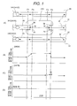
- "W" in Fig. 1 shows these temporary welding positions.
- the temporary welding W of the start end is carried out on upper faces of the raised portions 25, 35 and on the end faces in the longitudinal direction of the frame members 10, 20, 30, 40.
- the range of the temporary welding at the end is from the upper faces of the raised portions 25, 35 to the flanges 36.
- the temporary fixing welding "W” does not provide a V shape groove but provides an I shape groove.
- the end of the small diameter portion 341 of the rotary tool 340 is inserted into the upper face of the projecting rib 36.
- the position of the lower end of the large diameter portion 342 of the rotary tool 340 is between the level of the outer faces of the face plates 21, 31 and the top of the raised portions 25, 35, i.e. within the height extent of the raised portions.
- the position of the axis of the rotary tool 340 is between the two raised portions 25, 35.
- the small diameter portion 341 of the rotary tool 340 is a screw member.
- the rotary tool 340 on the joining line intersecting the window 210 is indicated as "340A” and the rotary tool 340 of the joining line having no window 210 is indicated as "340B".
- the rotary tools 340A and 340B are arranged on the same transverse line, and move from left to right in Fig. 1.
- the position P1 is determined by the travel speed of the traveller 320, and is determined in advance. See step S10 and step S30 in Fig. 2. After the friction stir joining, the flanges 28, 38 are cut off. For this reason, the position P1 is selected such that upstream from it there is no concern about the joint depth from the strength aspect.
- the rotary tool 340B where there is no window 210 is not raised, but continues the friction stir joining as it travels.
- the traveller 320 is made to stop. Since the ascent of the rotary tool 340B is continued, it is pulled out completely from the joint. At the position P4, the ascent speed of the rotary tool 340B may be increased.
- the position P4 is positioned downstream from the temporary welding portion W at the extremity of the flanges 29, 39. See step 90 and step 110 in Fig. 2.
- the distance between the position P3 and the position P4 is, for example, 50 mm.
- the ascent distance of the rotary tool 340B between the position P3 and the position P4 is, for example, 0.5 mm.
- the joint depth is reduced, but the minimum joint depth, is selected so that there is no problem from the viewpoint of the joint strength.
- a hole which corresponds to the diameter of the small diameter portion 341 of the rotary tool 340 is formed.
- all rotary tools 340A and 340B are rotated and lowered, to be inserted to the predetermined depth. See step S130.
- the rotary tool 340B is inserted into the hole which it left, to the regular depth, which is the same as before the position P3, i.e. before the start of the ascent of the tool 340B.
- the insertion depth is to where the previous friction stir joining is stopped plus 0.5 mm, i.e. 0.5 mm below the bottom of the hole which is generated when the rotary tool 340B is pulled out.
- the insertion position of the rotary tool 340A is formed at a location downstream from the temporary weld W of the end of the flanges 29, 39, a gap at the joining line is not significantly widened. Accordingly, good joining can be carried out.
- the body comprised of the plural hollow frame members is reversed (turned over) and friction stir joining is carried out in a similar manner on the other side, at face plates 22, 32.
- the residual raised portions at the outer face side of the car body are cut off and to make the outer face at the joint zones flush with the adjacent surface of the face plates.
- the rotary tool 340B is inserted more deeply, to make joining portion more thick. After the travel starts again, at a subsequent position P5 (or after a predetermined time) the rotary tool 340B is raised to the regular insertion depth.
- This ascent and other movements of the rotary tools 340 are carried out by a height position control function of the rotary tools 340.
- the height position control function determines the height position of the raised portions 25, 35 by means of the sensor and from this makes the insertion depth from the raised portions 25, 35 a predetermined value. In this way, all rotary tools 340 are brought to the regular condition.
- Another alternative operation is as follows.
- the friction stir joining is carried out with the regular insertion depth to the position P4 and at the position P4 the rotary tool 340B is pulled out.
- the rotary tools 340A and 340B are inserted again.
- the insertion depth of the rotary tool 340A is the regular amount.
- the insertion depth of the rotary tool 340B is larger than the regular amount, by for example 0.5 mm.
- the travel of the rotary tools 340A and 340B is restarted, and at a subsequent position (or after a predetermined time), the ascent of the rotary tool 340B starts.
- the ascent speed is slow, while travel of the traveller 320 continues.
- the joining depth according to the rotary tool 340B becomes shallow gradually.
- the ascent of the rotary tool 340B is stopped. Accordingly, all the rotary tools 340A and 340B achieve the regular condition.
- the positions P1, P2, P3 and P4 can be managed according to by measured time periods, or by position measurement.
- the rotary tool 340B is pulled out and re-inserted to the hole which is thus formed.
- the insertion amount during the second insertion of the rotary tool 340B is made the same as that during the previous joining operation.
- the position P5 where the insertion depth of the rotary tool 340A becomes regular is in the flanges 29 and 39. After joining, the flanges 29, 39 are cut off. The insertion depth of the rotary tool 340A is controlled according to the optical sensor.
- the gap at the joint line is not much enlarged. For this reason, good welding can be carried out. There is a risk that the gap between the two members at the insertion position (at the initiation of the joining line) may be enlarged, but in these embodiments not only the upper faces of the raised portions 25, 35 but also the ends of the flanges 29, 39 in the thickness direction are joined by the temporary welding W. Accordingly, the flanges are firmly joined, and the enlargement at the initiation of friction stir joining can be prevented.
- Flanges similar to the flanges 29, 39 may be provided at the first end portions of the hollow frame members 20, 30, namely at the first insertion positions of the rotary tools 340A and 340B arranged similarly to those of Fig. 6.
- the length of the flange can be shortened. Accordingly, the length of the hollow frame member can be shortened.
- the good friction stir joining in the case where the joining line having the plural lines is subjected to carry out at the same time with the friction stir joining and in the case where the portion in which the members to be subjected to the joining is not existed and the portion in which the friction stir joining is unnecessary and the portion for joining are mingled with, when the second time joining is made to start, the good friction stir joining can be obtained.
- the joining in the case where the joining line having the plural lines is subjected to carry out at the same time with the friction stir joining and in the case where the portion in which the members to be subjected to the joining is not existed and the portion in which the friction stir joining is unnecessary and the portion for joining are mingled with, when the second time joining is made to start, the joining can be carried out at the short time.
Landscapes
- Engineering & Computer Science (AREA)
- Mechanical Engineering (AREA)
- Life Sciences & Earth Sciences (AREA)
- Wood Science & Technology (AREA)
- Pressure Welding/Diffusion-Bonding (AREA)
Abstract
Description
- The present invention relates to a method of manufacturing a structural body by friction stir joining method and is applicable, for example, to manufacture of a car body of a railway vehicle.
- Friction stir joining is a method wherein a rotating round rod (called "rotary tool") inserted into a joint zone is moved along the joining line and the joint zone is heated, softened and solid-fluidized, so that a solid phase joining takes place.
- The rotary tool comprises a small diameter portion which is inserted into the joint zone, and a large diameter portion which is positioned adjacent the small diameter portion. The small diameter portion and the large diameter portion of the rotary tool are coaxial. The boundary or shoulder between the small diameter portion and the large diameter portion of the rotary tool is inserted a little way into the joint zone. The axis of the rotary tool may be inclined rearwardly with respect to the advancing direction of the tool during joining.
- In the manufacture of a car body of a railway vehicle it is known to carry out friction stir joining of extruded frame members, e.g. aluminium alloy members. The longitudinal direction of the extruded frame member is directed in the longitudinal direction of the car body, while the width direction of the extruded frame member is the circumferential direction of the car body.
- In the side of the car body with such a construction an opening such as a window is provided. See JP-A-09-309164 (EP-A-0797043).
- Since the height of a window of a car body is larger than the width of an extruded frame member, the window is formed in two or three frame members. For this reason, extruded frame members in which a cut-off portion or portions are provided substantially corresponding to the window are arranged together and joined.
- A friction stir joining apparatus for manufacturing the car body comprises a bed for mounting the extruded frame members and a traveller in which plural rotary tools are mounted. By the traveller plural rotary tools are moved and plural extruded frame members are joined simultaneously.
- If plural extruded frame members are joining simultaneously by rotary tools which are mounted below the traveller, when a first rotary tool reaches a position of a window, this rotary tool is retreated from the extruded frame members, and the friction stir joining is stopped, while a second rotary tool for joining a portion where the window does not exist continues the friction stir joining. When the traveller reaches the other end of the window, the first rotary tool is inserted into the joining zone starts friction stir joining again. In this process, when the first rotary tool is inserted to the joining zone, a defect in the joint can be generated easily. Further, at the beginning of the friction stir joining, since the temperature is not raised a large insertion force may be needed for inserting the rotary tool into the joining zone. In addition, since the rotary tool is moved to insert it, a slant force is generated at a bearing member of the rotary tool. The bearing member should be large, and the life of the rotary tool may be short.
- A first object of the present invention is to achieve good quality joining in a case where plural joining lines are joined simultaneously by friction stir joining, and there is a portion where the members being joined are gapped alongside a non-gapped portion. A second object is to reduce the time required for such a joining operation.
- In one aspect the invention provides a method of manufacturing a structural body, comprising the steps of:
- starting friction stir joining of a plurality of members by inserting respective rotary tools at two joining lines spaced laterally with respect to the direction of joint forming, and travelling the tools along the joining lines;
- at a first position, stopping the friction stir joining at one of said joining lines by withdrawing a first one of said tools from the joining material accompanying the travel of the second one of said tools;
- at a second position, stopping the travel of said tools and stopping the friction stir joining by withdrawing said second tool from the joining material;
- inserting said tools again to a predetermined depth at each joining line; and
- starting the friction stir joining again by starting the travel of the tools.
-
- In a second aspect, the invention provides a method of manufacturing a structural body, comprising the steps of:
- starting friction stir joining of a plurality of members by inserting respective rotary tools at two joining lines spaced laterally with respect to the direction of joint forming, and travelling the tools along the joining lines;
- at a first position, stopping the friction stir joining at one of said joining lines by withdrawing a first one of said tools from the joining material accompanying the travel of the second one of said tools;
- at a second position, reinserting said first rotary tool into the joining material to recommence its friction stir joining action.
-
- In a third aspect, the invention provides a method of manufacturing a structural body comprising the steps of:
- abutting two members at a mutual joint line thereof;
- welding adjacent faces of said abutted members at the joint line;
- joining said abutted members by friction stir joining by inserting a rotary tool at said faces and moving it in a travel direction along said joining line, wherein friction stir joining is started at a location downstream of the location of said welding in the travel direction.
-
-
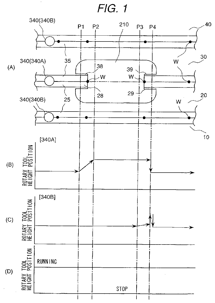
- Fig. 1 is a diagram of a method of manufacturing a structural body in one embodiment according to the present invention;
- Fig. 2 is a flowchart of the method of one embodiment according to the present invention;
- Fig. 3 is a longitudinal cross-sectional view showing portions of a structural body being made by a method of the present invention;
- Fig. 4 is a perspective view showing a friction stir joining apparatus used in one embodiment of the present invention;
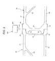
- Fig. 5 is a perspective view showing a car body of a railway vehicle which may be made by the present invention; and
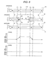
- Fig. 6 is a diagram of a method of manufacturing a structural body in another embodiment of the present invention.
-
- Figs. 1 to 5 show manufacture of a railway vehicle car body as an example of the invention. As shown in Fig. 5, the car body comprises a side
structural body 201 as a side face, a roofstructural body 202 as a roof, afloor frame 203, and an endstructural body 204 as an end portion in the longitudinal direction of the car body. - The
side body 201, theroof body 202, and thefloor frame 203 are constituted respectively by joining plural extruded frame members. The longitudinal (extrusion) direction of each frame member is directed in the longitudinal direction of the car body. The material of the extruded frame member is an aluminium alloy. - As shown in Fig. 5, the
side body 201 comprisesextruded frame members extruded frame members window 210 is present. An inlet and outlet port ordoor port 220 of theside body 201 is present in all theextruded frame members outlet port 220, after theextruded frame members window 210. The extrudedframe members outlet port 220. - This
side body 201 is shown to be of the fourextruded frame members side body 201 may be made of extruded frame members. Further, if thewindow 210 is constituted by three extruded frame members, the central frame member at the window is cut at an intermediate position. - Fig. 3 shows the
extruded frame members other frame members frame members - The
hollow frame member 20 comprises twoface plates plural ribs 23 connecting theplates plate 24 connecting the twoface plates hollow frame member 20. Thehollow frame member 30 comprises twoface plates plural ribs 33 connecting theplates plate 34 connecting the twoface plates hollow frame member 30. - At the end portion (the joining portion) of each of the
face plates portion 25 projecting above (away from) the face plate is provided. At the end portion (the joining portion) of each of theface plates portion 35 projecting above the face plate is provided. At the end portion thehollow frame member 30, has laterally projectingribs 36 for insertion into the opposedhollow frame member 20 between theface plates rotary tool 340. - The width of the raised
portions portions plate 34. The axis of therotary tool 340 of the frictionstir joining apparatus 330 is at the end faces of the raisedportions - The extruded
frame members side body 201 are mounted on abed 310 of the frictionstir joining apparatus 300 and fixed to thebed 310. Above the fixed extruded frame members a travellingframe 320 runs onrails 329 of both sides of thebed 310. Under a girder orbeam 321 of theframe 320 three frictionstir joining units 330 are mounted, with therotary tools 340 at their lower ends. The respective frictionstir joining units 330 can independently perform travel along thebeam 321, ascent and descent of therotary tool 340 and rotation of therotary tool 340. - Each friction
stir joining unit 330 has an optical sensor, which detects the distance from the top faces of the raisedportions rotary tool 340 at a predetermined value. Further, the optical sensor detects the width position of the raisedportions rotary tool 340 to coincide with the centre thereof. - In the extruded
frame members window 210 is provided, openings of substantially the window shape are provided at the position of the window in advance, by cutting theframe members - The
frame members port 220 is located are cut and arranged with a gap for theport 220. In theframe member 40 at the upper end of theport 220, an opening having substantially the desired port shape is provided at the position of theport 220 in advance, by cutting theframe member 40. - The cutting openings for the
window 210 will be explained. The joint zone of the twoframe members window 210. Theframe members flanges window 210. A width of therespective flanges plates portions port 220 is carried out similarly. Theframe members respective flanges such flanges side body 201. - When the
hollow frame members bed 310 the raisedportions chips portions frame members portions flanges 36. The temporary fixing welding "W" does not provide a V shape groove but provides an I shape groove. - In this condition, friction stir joining is started from one longitudinal end of the frame members is started. The
rotating rotary tools 340 are descended and inserted into the raisedportions tool 340A in the case of the window opening, the insertion position into theflanges - The end of the
small diameter portion 341 of therotary tool 340 is inserted into the upper face of the projectingrib 36. The position of the lower end of thelarge diameter portion 342 of therotary tool 340 is between the level of the outer faces of theface plates portions rotary tool 340 is between the two raisedportions small diameter portion 341 of therotary tool 340 is a screw member. - When the
rotary tools 340 on thetraveller 320 are inserted to the predetermined depths, the movement of thetraveller 320 with plural frictionstir joining devices 330 is started and the friction stir joining is carried out. - Next, operation of the friction
stir joining apparatus 330 at thewindow 210 and theport 220 will be explained referring to Figs. 1 and 2. Therotary tool 340 on the joining line intersecting thewindow 210 is indicated as "340A" and therotary tool 340 of the joining line having nowindow 210 is indicated as "340B". Therotary tools - The friction stir joining advancing from the left end of the extruded frame members when the
rotary tools flanges window 210, thetool 340A is retreated upwardly while rotating. The travel of the tools is continued. For this reason, therotary tool 340A ascends gradually. The position P1 is determined by the travel speed of thetraveller 320, and is determined in advance. See step S10 and step S30 in Fig. 2. After the friction stir joining, theflanges - The
rotary tool 340B where there is nowindow 210 is not raised, but continues the friction stir joining as it travels. - Since the
rotary tool 340A is raised while travelling, without stopping of the travel of thetools - When the
rotary tool 340A has ascended to a predetermined position (a position P2), its rotation is stopped. In the raised position of thetool 340A the tool is above the level of the raisedportions - When the
rotary tools window 210, namely a predetermined position P3 before the end of theflanges 29, 39 a shallow ascent (retreat) of therotary tool 340B starts. This travel of thetraveller 320 continues. The joint depth of therotary tool 340B reduces gradually. See step S50 and step S70 in Fig. 2. - When the position P4 which is in the longitudinal extent of
flanges traveller 320 is made to stop. Since the ascent of therotary tool 340B is continued, it is pulled out completely from the joint. At the position P4, the ascent speed of therotary tool 340B may be increased. The position P4 is positioned downstream from the temporary welding portion W at the extremity of theflanges - The distance between the position P3 and the position P4 is, for example, 50 mm. The ascent distance of the
rotary tool 340B between the position P3 and the position P4 is, for example, 0.5 mm. The joint depth is reduced, but the minimum joint depth, is selected so that there is no problem from the viewpoint of the joint strength. - When the
rotary tool 340B is pulled completely out, at the joining portion a hole which corresponds to the diameter of thesmall diameter portion 341 of therotary tool 340 is formed. Next, at the position P4, allrotary tools rotary tool 340B is inserted into the hole which it left, to the regular depth, which is the same as before the position P3, i.e. before the start of the ascent of thetool 340B. Namely, at the position P4, the insertion depth is to where the previous friction stir joining is stopped plus 0.5 mm, i.e. 0.5 mm below the bottom of the hole which is generated when therotary tool 340B is pulled out. - At this condition, the travel of the rotary tools is restarted, and the friction stir joining is started again, at the regular depth. See step S150.
- Thus in the position P4, friction stir joining is restarted at the hole which is formed by pulling out the
rotary tool 340B. For this reason, the hole is buried by the metal of the raisedportions rotary tool 340B is lower than the bottom end of the hole and since the lower portion of the hole is joined fully, the occurrence of a defect at this location can be avoided. In particular, since the metal at the lower portion of the hole is stirred fully by therotary tool 340B, a defect at the centre portion of the bottom end of the hole can be avoided. Since any defect may occur at the central portion of the bottom end of the hole, the defect amount is not large, from the aspect of the strength aspect a fully effective joint can be obtained. - Since the insertion position of the
rotary tool 340A is formed at a location downstream from the temporary weld W of the end of theflanges - At the
next window 210, the operation is similar. At the inlet andoutlet port 220 the ascent and the descent of therotary tools 340 is also carried out similarly. It is of course not necessary that allrotary tools 340 are arranged on the same transverse line. - After joining has carried out to the further end of the structure, the body comprised of the plural hollow frame members is reversed (turned over) and friction stir joining is carried out in a similar manner on the other side, at
face plates - If with the above described insertion depth of the
tool 340B at the position P4 there is a risk of a defect, therotary tool 340B is inserted more deeply, to make joining portion more thick. After the travel starts again, at a subsequent position P5 (or after a predetermined time) therotary tool 340B is raised to the regular insertion depth. - This ascent and other movements of the
rotary tools 340 are carried out by a height position control function of therotary tools 340. The height position control function determines the height position of the raisedportions portions 25, 35 a predetermined value. In this way, allrotary tools 340 are brought to the regular condition. - Another alternative operation is as follows. The friction stir joining is carried out with the regular insertion depth to the position P4 and at the position P4 the
rotary tool 340B is pulled out. Next, at the position P4 therotary tools rotary tool 340A is the regular amount. The insertion depth of therotary tool 340B is larger than the regular amount, by for example 0.5 mm. The travel of therotary tools rotary tool 340B starts. The ascent speed is slow, while travel of thetraveller 320 continues. The joining depth according to therotary tool 340B becomes shallow gradually. When therotary tool 340B has ascended to the predetermined position (the insertion depth before the position P4), the ascent of therotary tool 340B is stopped. Accordingly, all therotary tools - The positions P1, P2, P3 and P4 can be managed according to by measured time periods, or by position measurement.
- At the position when the
rotary tool 340B is pulled out and then therotary tool 340 can be inserted immediately, however with some reasons after the runningbody 320 is made to run, at the position P4 therotary tools - As described at the position P4, the
rotary tool 340B is pulled out and re-inserted to the hole which is thus formed. However it is possible to insert therotary tool 340B upstream of the position P4. In this case, the insertion amount during the second insertion of therotary tool 340B is made the same as that during the previous joining operation. - In the embodiment of Fig. 6, when the
rotary tools window 210, i.e. reach theflanges rotary tool 340A is descended while rotating and inserted to a predetermined depth. The insertion position P4 of therotary tool 340A into theflanges rotary tool 340A descends while travelling, the joint depth increases gradually. When the insertion depth reaches a predetermined amount, the descent of therotary tool 340A is stopped (position P5). Then friction stir joining with the regular depth is carried out. The position P5 where the insertion depth of therotary tool 340A becomes regular is in theflanges flanges rotary tool 340A is controlled according to the optical sensor. - Since the
rotary tool 340A is descended while travelling, there is no stopping of the travel of therotary tools - Since the insertion position P4 of the
rotary tool 340A is beyond the temporary welding portion of theflanges portions flanges - Flanges similar to the
flanges hollow frame members rotary tools - According to the first method of the present invention, in the case where the joining line having the plural lines is subjected to carry out at the same time with the friction stir joining and in the case where the portion in which the members to be subjected to the joining is not existed and the portion in which the friction stir joining is unnecessary and the portion for joining are mingled with, when the second time joining is made to start, the good friction stir joining can be obtained.
- According to the second method of the present invention, in the case where the joining line having the plural lines is subjected to carry out at the same time with the friction stir joining and in the case where the portion in which the members to be subjected to the joining is not existed and the portion in which the friction stir joining is unnecessary and the portion for joining are mingled with, when the second time joining is made to start, the joining can be carried out at the short time.
- The following numbered paragraphs contain statements of broad combinations of the inventive technical features herein disclosed:-
- 1. A method of manufacturing a structural body,
comprising the steps of:
- starting friction stir joining of a plurality of members by inserting respective rotary tools at two joining lines spaced laterally with respect to the direction of joint forming, and travelling the tools along the joining lines;
- at a first position, stopping the friction stir joining at one of said joining lines by withdrawing a first one of said tools from the joining material accompanying the travel of the second one of said tools;
- at a second position, stopping the travel of said tools and stopping the friction stir joining by withdrawing said second tool from the joining material;
- inserting said tools again to a predetermined depth at each joining line; and
- starting the friction stir joining again by starting the travel of the tools.
- 2. A method according to
paragraph 1, wherein after the withdrawal of said second tool at said second position, the tools are reinserted at said second position. - 3. A method according to paragraph 2, wherein the reinsertion depth of said second tool at said second position is deeper than its insertion depth immediately before its withdrawal at said second position.
- 4. A method according to
paragraph 1, wherein after withdrawal of said second tool at said second position, the position of reinsertion of said tools is upstream from said second position with respect to the travel direction. - 5. A method of manufacturing a structural body,
comprising the steps of:
- starting friction stir joining of a plurality of members by inserting respective rotary tools at two joining lines spaced laterally with respect to the direction of joint forming, and travelling the tools along the joining lines;
- at a first position, stopping the friction stir joining at one of said joining lines by withdrawing a first one of said tools from the joining material accompanying the travel of the second one of said tools;
- at a second position, starting withdrawal of said second tool and continuing the friction stir joining while withdrawing said second tool;
- at a third position, stopping the travel of said tool and stopping the friction stir joining by fully withdrawing said second rotary tool from said joining material;
- reinserting said tools to a predetermined depth in the joining portion material at each said joining line, the reinsertion depth of said second tool being deeper than the insertion depth thereof immediately before said withdrawal thereof at said third position; and
- restarting the friction stir joining by restarting the travel of the tools.
- 6. A method according to paragraph 5, wherein said reinsertion depth of said second tool at said third position is deeper than its insertion depth immediately before start of its withdrawal at said second position.
- 7. A method of manufacturing a structural body,
comprising the steps of:
- starting friction stir joining of a plurality of members by inserting respective rotary tools at two joining lines spaced laterally with respect to the direction of joint forming, and travelling the tools along the joining lines;
- at a first position, stopping the friction stir joining at one of said joining lines by withdrawing a first one of said tools from the joining material accompanying the travel of the second one of said tools;
- at a second position, stopping the travel of said tools and stopping the friction stir joining by withdrawing said second tool from the joining material;
- reinserting said tools to a predetermined depth at each joining line, the reinsertion depth of said second tool being deeper than its insertion depth before its withdrawal at said second position; and
- restarting the friction stir joining by restarting the travel of the tools, and reducing the insertion depth of said second tool to bring it to the insertion depth of said second rotary tool before travel is stopped at said second position.
- 8. A method of manufacturing a structural body,
comprising the steps of:
- starting friction stir joining of a plurality of members by inserting respective rotary tools at two joining lines spaced laterally with respect to the direction of joint forming, and travelling the tools along the joining lines;
- at a first position, stopping the friction stir joining at one of said joining lines by withdrawing a first one of said tools from the joining material accompanying the travel of the second one of said tools;
- at a second position, reinserting said first rotary tool into the joining material to recommence its friction stir joining action.
- 9. A method of manufacturing a structural body in
which friction stir joining of a plurality of members is
performed by travelling respective rotating tools
simultaneously along two joining lines spaced laterally
with respect to the travel direction, including the steps
of:-
- at a first intermediate position in the travel of the tools, withdrawing a first one of said tools from the joining material; and
- at a second intermediate position in the travel of the tools, re-inserting said first tool into the joining material to re-start friction stir joining by said first tool, said second intermediate position being downstream in said travel direction from a location at which the members have previously been joined at the joining line of said first tool so as to resist their separation by the reinsertion of said first tool.
- 10. A method according to paragraph 9, including the step of, after the friction stir joining.
- 11. A method of manufacturing a structural body
comprising the steps of:
- abutting two members at a mutual joint line thereof;
- welding adjacent faces of said abutted members at the joint line;
- joining said abutted members by friction stir joining by inserting a rotary tool at said faces and moving it in a travel direction along said joining line, wherein friction stir joining is started at a location downstream of the location of said welding in the travel direction.
- 12. A method according to paragraph 11, wherein said welding step includes welding said members together at faces extending in their thickness direction away from said faces.
- 13. A method of a structural body according to paragraph 11, wherein at least one of said members is a hollow frame member, and the welding is carried out from a seat for supporting a face plate of an opposite part of said hollow frame member.
- 14. A method of manufacturing a structural body
comprising the steps of:
- mounting two members abutted together on a bed (which may be curved);
- welding said members together at abutted portions of side faces thereof and at abutted portion of end faces thereof;
- joining said members by friction stir joining by moving a rotary tool along a joining line, the friction stir joining being started by inserting said rotary tool adjacent the location of said welding and downstream thereof in the tool movement direction.
-
Claims (5)
- A method of manufacturing a structural body comprising the steps of:abutting two members (10, 20, 30, 40)at a mutual joint line thereof;welding adjacent faces of said abutted members at the joint line;joining said abutted members by friction stir joining by inserting a rotary tool (340) at said faces and moving it in a travel direction along said joint line, wherein friction stir joining is started at a location downstream in said travel direction with respect to the location (W) of said welding.
- A method according to claim 1, wherein said welding step includes welding said members together at end faces extending in their thickness direction away from said faces.
- A method of a structural body according to claim 2, wherein said members are hollow frame members, and the welding at said end faces is carried out down to seats (36) for supporting the respective adjacent hollow frame members.
- A method according to any one of claims 1 to 3, comprising the step of mounting the two members abutted together on a bed, prior to the welding of said members and their joining by friction stir joining.
- A method according to claim 4, wherein said bed is curved.
Applications Claiming Priority (7)
| Application Number | Priority Date | Filing Date | Title |
|---|---|---|---|
| JP15113199A JP3480913B2 (en) | 1999-05-31 | 1999-05-31 | How to make a structure |
| JP15113199 | 1999-05-31 | ||
| JP15112999 | 1999-05-31 | ||
| JP15113099 | 1999-05-31 | ||
| JP15113099A JP3459199B2 (en) | 1999-05-31 | 1999-05-31 | How to make a structure |
| JP15112999A JP3459198B2 (en) | 1999-05-31 | 1999-05-31 | How to make a structure |
| EP00304563A EP1057576B1 (en) | 1999-05-31 | 2000-05-30 | A method of manufacturing a structual body with friction stir welding |
Related Parent Applications (1)
| Application Number | Title | Priority Date | Filing Date |
|---|---|---|---|
| EP00304563A Division EP1057576B1 (en) | 1999-05-31 | 2000-05-30 | A method of manufacturing a structual body with friction stir welding |
Publications (2)
| Publication Number | Publication Date |
|---|---|
| EP1310320A1 true EP1310320A1 (en) | 2003-05-14 |
| EP1310320B1 EP1310320B1 (en) | 2004-11-10 |
Family
ID=27320061
Family Applications (2)
| Application Number | Title | Priority Date | Filing Date |
|---|---|---|---|
| EP03001519A Expired - Lifetime EP1310320B1 (en) | 1999-05-31 | 2000-05-30 | A friction stir welding method of manufacturing a structural body with provisional/tack welding of parts from the structural body |
| EP00304563A Expired - Lifetime EP1057576B1 (en) | 1999-05-31 | 2000-05-30 | A method of manufacturing a structual body with friction stir welding |
Family Applications After (1)
| Application Number | Title | Priority Date | Filing Date |
|---|---|---|---|
| EP00304563A Expired - Lifetime EP1057576B1 (en) | 1999-05-31 | 2000-05-30 | A method of manufacturing a structual body with friction stir welding |
Country Status (7)
| Country | Link |
|---|---|
| US (4) | US6273323B1 (en) |
| EP (2) | EP1310320B1 (en) |
| KR (1) | KR100502814B1 (en) |
| CN (2) | CN1188230C (en) |
| AU (1) | AU747027B2 (en) |
| DE (2) | DE60015815T2 (en) |
| TW (1) | TW449519B (en) |
Cited By (3)
| Publication number | Priority date | Publication date | Assignee | Title |
|---|---|---|---|---|
| RU2289496C1 (en) * | 2005-06-08 | 2006-12-20 | Федеральное государственное унитарное предприятие "Государственный космический научно-производственный центр им. М.В. Хруничева" | Method of friction welding with displacement of blank materials (versions) |
| RU2445196C2 (en) * | 2006-04-20 | 2012-03-20 | Юропиан Аэронотик Дефенс Энд Спейс Компани Эадс Франс | Method of friction welding with mixing using retractable rod device, said retractable rod being retracted at path end |
| CN109676237A (en) * | 2019-01-07 | 2019-04-26 | 湖南坤鼎数控科技有限公司 | A kind of gantry friction welding apparatus |
Families Citing this family (51)
| Publication number | Priority date | Publication date | Assignee | Title |
|---|---|---|---|---|
| JP3070735B2 (en) * | 1997-07-23 | 2000-07-31 | 株式会社日立製作所 | Friction stir welding method |
| TW449519B (en) * | 1999-05-31 | 2001-08-11 | Hitachi Ltd | A manufacturing method of a structure body |
| JP3563003B2 (en) * | 1999-09-30 | 2004-09-08 | 株式会社日立製作所 | Friction stir welding method for structures |
| JP3552978B2 (en) * | 2000-01-27 | 2004-08-11 | 株式会社日立製作所 | Hollow profile |
| CN1191144C (en) | 2000-05-08 | 2005-03-02 | 布莱阿姆青年大学 | Superabrasive tools and methods for friction stir welding |
| US6619533B1 (en) * | 2000-09-22 | 2003-09-16 | Tower Automotive Technology Products, Inc. | Multi-piece extruded link arm |
| JP3538378B2 (en) | 2000-10-27 | 2004-06-14 | 株式会社日立製作所 | Friction stir welding method |
| US6732901B2 (en) | 2001-06-12 | 2004-05-11 | Brigham Young University Technology Transfer Office | Anvil for friction stir welding high temperature materials |
| JP3751236B2 (en) * | 2001-08-24 | 2006-03-01 | 株式会社日立製作所 | Friction stir welding method |
| US20030098335A1 (en) * | 2001-11-27 | 2003-05-29 | Takehiko Saeki | Rotating tool for friction stir welding, and method and apparatus of friction stir welding using it |
| US7270257B2 (en) | 2003-01-30 | 2007-09-18 | Sii Megadiamond, Inc. | Out-of-position friction stir welding of high melting temperature alloys |
| US6908145B2 (en) * | 2003-02-10 | 2005-06-21 | Ford Global Technologies, Llc | Vehicle passenger compartment components and manufacturing process for making the same |
| US7523850B2 (en) * | 2003-04-07 | 2009-04-28 | Luxfer Group Limited | Method of forming and blank therefor |
| US7530486B2 (en) | 2003-05-05 | 2009-05-12 | Sii Megadiamond, Inc. | Applications of friction stir welding using a superabrasive tool |
| WO2005084162A2 (en) | 2003-08-04 | 2005-09-15 | Smith International, Inc. | Crack repair using friction stir welding on materials including metal matrix composites, ferrous alloys, non-ferrous alloys, and superalloys |
| US20050070374A1 (en) * | 2003-09-29 | 2005-03-31 | Technology Licensing, Llc | Enhanced golf club performance via friction stir processing |
| US7576170B2 (en) | 2003-12-19 | 2009-08-18 | Momentive Performance Materials | Cyclic siloxane compositions for the release of active ingredients |
| US7579495B2 (en) * | 2003-12-19 | 2009-08-25 | Momentive Performance Materials Inc. | Active-releasing cyclic siloxanes |
| US20060032333A1 (en) | 2004-03-24 | 2006-02-16 | Steel Russell J | Solid state processing of industrial blades, edges and cutting elements |
| US20100078224A1 (en) | 2004-05-21 | 2010-04-01 | Smith International, Inc. | Ball hole welding using the friction stir welding (fsw) process |
| US7401723B2 (en) * | 2004-08-30 | 2008-07-22 | Alcoa Inc. | Advanced friction stir welding tools |
| US7383975B2 (en) | 2004-08-30 | 2008-06-10 | Alcoa Inc. | Fracture resistant friction stir welding tools |
| US7198189B2 (en) * | 2004-09-28 | 2007-04-03 | Alcoa Inc. | Multi-shouldered fixed bobbin tools for simultaneous friction stir welding of multiple parallel walls between parts |
| CA2582732C (en) | 2004-10-05 | 2012-09-11 | Sii Megadiamond, Inc. | Expandable mandrel for use in friction stir welding |
| US20080041921A1 (en) | 2005-09-26 | 2008-02-21 | Kevin Creehan | Friction stir fabrication |
| US9511446B2 (en) | 2014-12-17 | 2016-12-06 | Aeroprobe Corporation | In-situ interlocking of metals using additive friction stir processing |
| US9266191B2 (en) | 2013-12-18 | 2016-02-23 | Aeroprobe Corporation | Fabrication of monolithic stiffening ribs on metallic sheets |
| US8632850B2 (en) | 2005-09-26 | 2014-01-21 | Schultz-Creehan Holdings, Inc. | Friction fabrication tools |
| US9511445B2 (en) | 2014-12-17 | 2016-12-06 | Aeroprobe Corporation | Solid state joining using additive friction stir processing |
| US8875976B2 (en) | 2005-09-26 | 2014-11-04 | Aeroprobe Corporation | System for continuous feeding of filler material for friction stir welding, processing and fabrication |
| US8550326B2 (en) | 2005-10-05 | 2013-10-08 | Megastir Technologies Llc | Expandable mandrel for use in friction stir welding |
| US8056797B2 (en) | 2005-10-05 | 2011-11-15 | Megastir Technologies | Expandable mandrel for use in friction stir welding |
| US7992761B2 (en) * | 2006-10-05 | 2011-08-09 | The Boeing Company | Process control system for friction stir welding |
| US20080217377A1 (en) * | 2007-03-06 | 2008-09-11 | Alcoa Inc. | Fracture Resistant Friction Stir Welding Tool |
| CN102814589B (en) * | 2007-08-10 | 2014-06-25 | 日本轻金属株式会社 | Joining method and method for manufacturing joined structure |
| US7793816B2 (en) * | 2007-09-07 | 2010-09-14 | Alcoa Inc. | Friction stir welding apparatus |
| US7854362B2 (en) | 2008-03-14 | 2010-12-21 | Alcoa Inc. | Advanced multi-shouldered fixed bobbin tools for simultaneous friction stir welding of multiple parallel walls between parts |
| US9168608B2 (en) * | 2009-04-16 | 2015-10-27 | Davide Vaia | Welding head for rail welding |
| CA2779075C (en) | 2009-11-02 | 2016-05-10 | Megastir Technologies Llc | Out of position friction stir welding of casing and small diameter tubing or pipe |
| US9091489B2 (en) | 2010-05-14 | 2015-07-28 | Paragon Space Development Corporation | Radiator systems |
| JP2012183565A (en) * | 2011-03-07 | 2012-09-27 | Suzuki Motor Corp | Friction stir welding method and welding jig |
| WO2013002869A2 (en) | 2011-04-07 | 2013-01-03 | Schultz-Creehan Holdings, Inc. | System for continuous feeding of filler material for friction stir fabrication and self-reacting friction stir welding tool |
| CN105026096B (en) * | 2013-04-25 | 2017-11-21 | 三菱重工业株式会社 | The manufacture method of friction-stir welding tool, friction-stir engagement device and grafting material |
| CN103671075B (en) * | 2013-12-11 | 2016-08-10 | 中联重科股份有限公司 | Cutting ring and method of manufacturing the same |
| JP2017524536A (en) * | 2014-07-10 | 2017-08-31 | エサブ・アーベー | Floating fixture for friction stir welding |
| FR3037267B1 (en) * | 2015-06-09 | 2017-11-17 | Airbus Helicopters | METHOD AND TOOL FOR FRICTION MOLDING SINK |
| US20170050263A1 (en) * | 2015-08-21 | 2017-02-23 | Amulaire Thermal Technology, Inc. | Friction stir welding device and method of friction stir welding |
| WO2019089764A1 (en) | 2017-10-31 | 2019-05-09 | Aeroprobe Corporation | Solid-state additive manufacturing system and material compositions and structures |
| US11794271B2 (en) * | 2018-07-19 | 2023-10-24 | Nippon Light Metal Company, Ltd. | Method for manufacturing liquid-cooled jacket |
| CN110064837B (en) * | 2019-06-06 | 2021-08-17 | 中车株洲电力机车有限公司 | Friction stir welding device and profile welding method |
| CN110497121A (en) * | 2019-08-05 | 2019-11-26 | 苏州热工研究院有限公司 | The image processing mode of welding bead center tracking in a kind of welding process |
Citations (6)
| Publication number | Priority date | Publication date | Assignee | Title |
|---|---|---|---|---|
| EP0579500A1 (en) * | 1992-07-17 | 1994-01-19 | Hitachi, Ltd. | Railway cars and methods of manufacture thereof |
| DE19624776C1 (en) * | 1996-06-21 | 1997-09-04 | Krupp Ag Hoesch Krupp | Welded steel sheet production from sheet sections |
| EP0797043A2 (en) * | 1996-03-19 | 1997-09-24 | Hitachi, Ltd. | Panel structure, a friction welding method, and a panel |
| EP0893190A2 (en) * | 1997-07-23 | 1999-01-27 | Hitachi, Ltd. | Constructive body and friction stir welding method |
| JPH11179568A (en) * | 1997-12-24 | 1999-07-06 | Nippon Light Metal Co Ltd | Friction stir welding method |
| EP0992314A2 (en) * | 1998-09-29 | 2000-04-12 | Hitachi, Ltd. | Friction stir welding and welded structures produced thereby |
Family Cites Families (18)
| Publication number | Priority date | Publication date | Assignee | Title |
|---|---|---|---|---|
| DE3813841A1 (en) | 1987-06-03 | 1988-12-15 | Bayer Ag | HETEROCYCLIC HYDROXYETHYLAZOLES |
| TW200434B (en) * | 1990-09-07 | 1993-02-21 | Hitachi Seisakusyo Kk | |
| GB9125978D0 (en) * | 1991-12-06 | 1992-02-05 | Welding Inst | Hot shear butt welding |
| DE4344561C2 (en) | 1993-12-24 | 1995-11-30 | Daimler Benz Ag | Method and device for friction welding of cylindrical parts to be joined |
| NO942790D0 (en) * | 1994-03-28 | 1994-07-27 | Norsk Hydro As | Method of friction welding and device for the same |
| CN1035527C (en) * | 1994-09-09 | 1997-07-30 | 宝山钢铁(集团)公司 | welding process for steel plate with organic coating |
| DE19524776A1 (en) | 1995-07-07 | 1997-01-09 | Geze Gmbh & Co | Automatic door closing arrangement - uses hydraulic piston cylinder system for damping |
| US5718366A (en) * | 1996-05-31 | 1998-02-17 | The Boeing Company | Friction stir welding tool for welding variable thickness workpieces |
| US5697511A (en) * | 1996-09-27 | 1997-12-16 | Boeing North American, Inc. | Tank and method of fabrication |
| JP3333411B2 (en) * | 1996-12-18 | 2002-10-15 | 株式会社日立製作所 | Friction stir welding method and friction stir welding device |
| JP3045682B2 (en) * | 1997-01-17 | 2000-05-29 | 昭和アルミニウム株式会社 | Friction stir welding |
| US6105902A (en) * | 1997-07-15 | 2000-08-22 | Mcdonnell Douglas Corporation | Aircraft fuselage and method of forming same |
| JP3070735B2 (en) * | 1997-07-23 | 2000-07-31 | 株式会社日立製作所 | Friction stir welding method |
| JP3874132B2 (en) * | 1997-08-05 | 2007-01-31 | 日本軽金属株式会社 | Honeycomb panel and manufacturing method thereof |
| US6051325A (en) * | 1997-12-23 | 2000-04-18 | Mcdonnell Douglas Corporation | Joining of machined sandwich assemblies by friction stir welding |
| US6168067B1 (en) * | 1998-06-23 | 2001-01-02 | Mcdonnell Douglas Corporation | High strength friction stir welding |
| US6045028A (en) * | 1998-07-17 | 2000-04-04 | Mcdonnell Douglas Corporation | Integral corrosion protection of friction-welded joints |
| TW449519B (en) * | 1999-05-31 | 2001-08-11 | Hitachi Ltd | A manufacturing method of a structure body |
-
2000
- 2000-05-12 TW TW089109171A patent/TW449519B/en not_active IP Right Cessation
- 2000-05-17 US US09/572,985 patent/US6273323B1/en not_active Expired - Fee Related
- 2000-05-22 AU AU36342/00A patent/AU747027B2/en not_active Ceased
- 2000-05-30 EP EP03001519A patent/EP1310320B1/en not_active Expired - Lifetime
- 2000-05-30 DE DE60015815T patent/DE60015815T2/en not_active Expired - Lifetime
- 2000-05-30 DE DE60006450T patent/DE60006450T2/en not_active Expired - Lifetime
- 2000-05-30 EP EP00304563A patent/EP1057576B1/en not_active Expired - Lifetime
- 2000-05-30 KR KR10-2000-0029195A patent/KR100502814B1/en not_active Expired - Fee Related
- 2000-05-31 CN CNB001087479A patent/CN1188230C/en not_active Expired - Lifetime
- 2000-05-31 CN CNB2004100334723A patent/CN1311948C/en not_active Expired - Lifetime
-
2001
- 2001-04-12 US US09/832,911 patent/US6325274B2/en not_active Expired - Fee Related
- 2001-04-12 US US09/835,778 patent/US6502739B2/en not_active Expired - Fee Related
- 2001-10-16 US US09/977,700 patent/US6513698B2/en not_active Expired - Fee Related
Patent Citations (6)
| Publication number | Priority date | Publication date | Assignee | Title |
|---|---|---|---|---|
| EP0579500A1 (en) * | 1992-07-17 | 1994-01-19 | Hitachi, Ltd. | Railway cars and methods of manufacture thereof |
| EP0797043A2 (en) * | 1996-03-19 | 1997-09-24 | Hitachi, Ltd. | Panel structure, a friction welding method, and a panel |
| DE19624776C1 (en) * | 1996-06-21 | 1997-09-04 | Krupp Ag Hoesch Krupp | Welded steel sheet production from sheet sections |
| EP0893190A2 (en) * | 1997-07-23 | 1999-01-27 | Hitachi, Ltd. | Constructive body and friction stir welding method |
| JPH11179568A (en) * | 1997-12-24 | 1999-07-06 | Nippon Light Metal Co Ltd | Friction stir welding method |
| EP0992314A2 (en) * | 1998-09-29 | 2000-04-12 | Hitachi, Ltd. | Friction stir welding and welded structures produced thereby |
Non-Patent Citations (1)
| Title |
|---|
| PATENT ABSTRACTS OF JAPAN vol. 1999, no. 12 29 October 1999 (1999-10-29) * |
Cited By (4)
| Publication number | Priority date | Publication date | Assignee | Title |
|---|---|---|---|---|
| RU2289496C1 (en) * | 2005-06-08 | 2006-12-20 | Федеральное государственное унитарное предприятие "Государственный космический научно-производственный центр им. М.В. Хруничева" | Method of friction welding with displacement of blank materials (versions) |
| RU2445196C2 (en) * | 2006-04-20 | 2012-03-20 | Юропиан Аэронотик Дефенс Энд Спейс Компани Эадс Франс | Method of friction welding with mixing using retractable rod device, said retractable rod being retracted at path end |
| CN109676237A (en) * | 2019-01-07 | 2019-04-26 | 湖南坤鼎数控科技有限公司 | A kind of gantry friction welding apparatus |
| CN109676237B (en) * | 2019-01-07 | 2021-06-22 | 湖南坤鼎数控科技有限公司 | A gantry friction welding equipment |
Also Published As
| Publication number | Publication date |
|---|---|
| TW449519B (en) | 2001-08-11 |
| EP1057576A2 (en) | 2000-12-06 |
| DE60006450D1 (en) | 2003-12-18 |
| US20020017551A1 (en) | 2002-02-14 |
| EP1310320B1 (en) | 2004-11-10 |
| DE60015815D1 (en) | 2004-12-16 |
| US20020030082A1 (en) | 2002-03-14 |
| EP1057576B1 (en) | 2003-11-12 |
| EP1057576A3 (en) | 2001-12-19 |
| CN1188230C (en) | 2005-02-09 |
| CN1275451A (en) | 2000-12-06 |
| DE60006450T2 (en) | 2004-08-26 |
| KR100502814B1 (en) | 2005-07-20 |
| US6502739B2 (en) | 2003-01-07 |
| DE60015815T2 (en) | 2005-12-22 |
| AU3634200A (en) | 2000-12-14 |
| US6273323B1 (en) | 2001-08-14 |
| KR20010049442A (en) | 2001-06-15 |
| US20010011674A1 (en) | 2001-08-09 |
| CN1532019A (en) | 2004-09-29 |
| US6513698B2 (en) | 2003-02-04 |
| CN1311948C (en) | 2007-04-25 |
| US6325274B2 (en) | 2001-12-04 |
| AU747027B2 (en) | 2002-05-09 |
Similar Documents
| Publication | Publication Date | Title |
|---|---|---|
| EP1057576B1 (en) | A method of manufacturing a structual body with friction stir welding | |
| US6321975B1 (en) | Manufacturing method of a structure body | |
| RU2185266C2 (en) | Method and system for welding rails of railway roads | |
| EP1331309B1 (en) | Method for welding rails for railway carriages | |
| DE10034096B4 (en) | Method for welding steel rails | |
| EP1287940B1 (en) | Friction stir welding method of a rim with a plate | |
| JP3480913B2 (en) | How to make a structure | |
| JP3459198B2 (en) | How to make a structure | |
| JP3459199B2 (en) | How to make a structure | |
| JP3732680B2 (en) | Manufacturing method of structure | |
| JP2002059275A (en) | How to make a structure | |
| JP2002035966A (en) | How to make a structure | |
| US4601189A (en) | Method of and tool for mitering frame members | |
| WO1996000183A1 (en) | Procedure for the manufacture of elevator guide rails | |
| JP2002059278A (en) | Friction stir welding method | |
| JP2002059276A (en) | How to make a structure |
Legal Events
| Date | Code | Title | Description |
|---|---|---|---|
| PUAI | Public reference made under article 153(3) epc to a published international application that has entered the european phase |
Free format text: ORIGINAL CODE: 0009012 |
|
| 17P | Request for examination filed |
Effective date: 20030211 |
|
| AC | Divisional application: reference to earlier application |
Ref document number: 1057576 Country of ref document: EP Kind code of ref document: P |
|
| AK | Designated contracting states |
Designated state(s): DE FR GB IT SE |
|
| 17Q | First examination report despatched |
Effective date: 20030827 |
|
| AKX | Designation fees paid |
Designated state(s): DE FR GB IT SE |
|
| GRAP | Despatch of communication of intention to grant a patent |
Free format text: ORIGINAL CODE: EPIDOSNIGR1 |
|
| GRAS | Grant fee paid |
Free format text: ORIGINAL CODE: EPIDOSNIGR3 |
|
| GRAA | (expected) grant |
Free format text: ORIGINAL CODE: 0009210 |
|
| RIN1 | Information on inventor provided before grant (corrected) |
Inventor name: EZUMI, MASAKUNI Inventor name: SATOU, AKIHIRO Inventor name: FUKUYORI, KAZUSIGE |
|
| AC | Divisional application: reference to earlier application |
Ref document number: 1057576 Country of ref document: EP Kind code of ref document: P |
|
| AK | Designated contracting states |
Kind code of ref document: B1 Designated state(s): DE FR GB IT SE |
|
| REG | Reference to a national code |
Ref country code: GB Ref legal event code: FG4D |
|
| REF | Corresponds to: |
Ref document number: 60015815 Country of ref document: DE Date of ref document: 20041216 Kind code of ref document: P |
|
| REG | Reference to a national code |
Ref country code: SE Ref legal event code: TRGR |
|
| PLBE | No opposition filed within time limit |
Free format text: ORIGINAL CODE: 0009261 |
|
| STAA | Information on the status of an ep patent application or granted ep patent |
Free format text: STATUS: NO OPPOSITION FILED WITHIN TIME LIMIT |
|
| 26N | No opposition filed |
Effective date: 20050811 |
|
| ET | Fr: translation filed | ||
| REG | Reference to a national code |
Ref country code: FR Ref legal event code: PLFP Year of fee payment: 17 |
|
| REG | Reference to a national code |
Ref country code: FR Ref legal event code: PLFP Year of fee payment: 18 |
|
| REG | Reference to a national code |
Ref country code: FR Ref legal event code: PLFP Year of fee payment: 19 |
|
| PGFP | Annual fee paid to national office [announced via postgrant information from national office to epo] |
Ref country code: DE Payment date: 20190514 Year of fee payment: 20 Ref country code: IT Payment date: 20190527 Year of fee payment: 20 |
|
| PGFP | Annual fee paid to national office [announced via postgrant information from national office to epo] |
Ref country code: FR Payment date: 20190410 Year of fee payment: 20 Ref country code: SE Payment date: 20190513 Year of fee payment: 20 |
|
| PGFP | Annual fee paid to national office [announced via postgrant information from national office to epo] |
Ref country code: GB Payment date: 20190529 Year of fee payment: 20 |
|
| REG | Reference to a national code |
Ref country code: DE Ref legal event code: R071 Ref document number: 60015815 Country of ref document: DE |
|
| REG | Reference to a national code |
Ref country code: GB Ref legal event code: PE20 Expiry date: 20200529 |
|
| REG | Reference to a national code |
Ref country code: SE Ref legal event code: EUG |
|
| PG25 | Lapsed in a contracting state [announced via postgrant information from national office to epo] |
Ref country code: GB Free format text: LAPSE BECAUSE OF EXPIRATION OF PROTECTION Effective date: 20200529 |