EP1309239B1 - Tränkvorrichtung für tiere - Google Patents
Tränkvorrichtung für tiere Download PDFInfo
- Publication number
- EP1309239B1 EP1309239B1 EP00955184A EP00955184A EP1309239B1 EP 1309239 B1 EP1309239 B1 EP 1309239B1 EP 00955184 A EP00955184 A EP 00955184A EP 00955184 A EP00955184 A EP 00955184A EP 1309239 B1 EP1309239 B1 EP 1309239B1
- Authority
- EP
- European Patent Office
- Prior art keywords
- cover
- trough
- water
- receptacle
- animal
- Prior art date
- Legal status (The legal status is an assumption and is not a legal conclusion. Google has not performed a legal analysis and makes no representation as to the accuracy of the status listed.)
- Expired - Lifetime
Links
Images

Classifications
-
- A—HUMAN NECESSITIES
- A01—AGRICULTURE; FORESTRY; ANIMAL HUSBANDRY; HUNTING; TRAPPING; FISHING
- A01K—ANIMAL HUSBANDRY; AVICULTURE; APICULTURE; PISCICULTURE; FISHING; REARING OR BREEDING ANIMALS, NOT OTHERWISE PROVIDED FOR; NEW BREEDS OF ANIMALS
- A01K7/00—Watering equipment for stock or game
-
- A—HUMAN NECESSITIES
- A01—AGRICULTURE; FORESTRY; ANIMAL HUSBANDRY; HUNTING; TRAPPING; FISHING
- A01K—ANIMAL HUSBANDRY; AVICULTURE; APICULTURE; PISCICULTURE; FISHING; REARING OR BREEDING ANIMALS, NOT OTHERWISE PROVIDED FOR; NEW BREEDS OF ANIMALS
- A01K7/00—Watering equipment for stock or game
- A01K7/02—Automatic devices
- A01K7/025—Water tanks
Definitions
- This invention relates generally to animal watering apparatus.
- the invention includes a device to dispense health and food supplements to farm animals.
- Troughs to water farm animals are common place.
- Troughs normally have a system for automatically replenishing water consumed by animals such as a valve connected to a ball-cock mechanism.
- the exposed nature of conventional troughs means the water within the trough may become contaminated by outside matter such as sprays and fertiliser.
- the exposed nature of the trough also promotes algae growth which can foul the water or make the trough undesirable for animals to drink from.
- Foreign bodies such as branches, plant matter, rubbish, bird droppings and so forth, may also be introduced to the trough and increase the risk of bacteria, such as Salmonella or Botulism, being passed to the animals drinking from the trough.
- the troughs must be cleaned and foreign matter removed, which can at times be time consuming and labourious.
- US Patent Number 4739727 discloses an animal waterer having an insulated container for holding water, a supply conduit for supplying water under pressure to the container and a valve connected to the supply conduit for maintaining the water in the container substantially at a predetermined level.
- An insulated lid is sealingly attached to the top of the container and has a pair of openings in it each large enough to permit an animal to extend its mouth through for the purpose of drinking water from the container.
- a flexible length member extends between and is rotatably attached to two closure members at each end of the length and is used to close off the openings in the container.
- a biasing structure preferably a cable extending over a pulley and having a weight attached to one end, where the other end is attached to an intermediate part of a link member, holds the closure members against the bottom of the openings the container to keep them closed at all times except when an animal is pushing them down to drink from the container.
- the apparatus of this invention is complex and difficult to install.
- Farm animals require regular watering, and often need to receive medical or nutritional supplements, such as minerals and zinc. Therefore, the provision of a supplement dispensing device within a trough may be advantageous.
- treatment substances such as medicaments or nutrients via the animals drinking water in such a trough. It may also be desirable to release the substance into the water over time, rather than simply mixing the substance into the water, as correct concentrations may need to be maintained over time. It is also inconvenient to have to continually go to troughs and top up the substance volume.
- New Zealand Patent No. 260398 provides a bag or a sock into which a substance can be introduced, wherein the bag is placed in a trough for slow release of the substance.
- the problems associated with debris, algae, and other foreign contamination of the water still persist.
- the ball-cock mechanisms used in the troughs to maintain the water level are often damaged by farm animals drinking from the trough. This may lead to the water valve remaining on and causing water wastage, or remaining off and causing the trough to dry up.
- an animal watering apparatus comprising:
- the invention may broadly be said to consist in a cover for an animal drinking trough comprising:
- the invention may broadly be said to consist in a method of protecting the water in an animal drinking trough by covering the top of said trough and allowing animals access to only a small exposed area of water using the trough cover defined above comprising the steps of:
- the present invention provides a cover structure for water troughs, tanks, pans or other waterers to provide uncontaminated drinking water for animals and also envisages a complete watering apparatus including the cover structure in combination with the trough.
- the cover fits within the trough and floats on the water within the trough.
- the water is accessed by the animals from a channel built into the cover which exposes a water surface area which is a small fraction of the exposed water surface in the open trough.
- a dispenser may be located in the cover, to dispense nutrients, medicaments or water treatments to the trough water.
- the cover preferably floats on top of the water within the trough
- the cover may be provided so as to fit onto the periphery of the trough.
- the cover may be mechanically supported or attached within the trough.
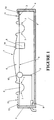
- a cover 1 floats on top of a body of water 2, that has a water level as indicated by the line 3, contained in the trough 4.
- the cover 1 is moulded from a polyethylene material as a single unit.
- the cover 1 floats on top of the water due to the buoyancy of the cover. This buoyancy is provided by both the material in which the cover is made of, and the shape of the cover, which increases the volume of water displaced, namely, the volume 5 between the cover 1 and water 2.
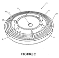
- the cover 1, as shown in Figure 2 is preferably circular in shape, so as to fit within conventional circular troughs. While one aspect of the invention involves retrofitting covers to existing troughs insitu, the manufacture of a trough with matching cover is also envisaged. Although in the preferred form the trough 4 is circular in horizontal cross-section other shapes may be used, or in the case of retrofitting an existing trough other shapes must be accommodated. For example, trough shape may be country specific or animal specific. Therefore, the cover 1 may be provided in an alternative shape, such as square, rectangular or octagonal to be able to be fitted into respectively shaped troughs 4. In the preferred form, the cover 1 has a perimeter slightly less than the trough 4 to allow it to float freely within the trough walls.
- the cover should stay in a fixed relationship with the water level.
- Some known troughs have tapered sides and with a floating cover when the water level within the trough falls the cover may become lodged on the sides of the trough and possibly terminating the flow of water from the trough into the channel 6.
- the cover may be provided with an adjustable skirt, such as flexible brushes, to allow the cover's effective inside perimeter to be reduced as the cover falls with the falling water level.
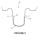
- the cover 1 is formed with a water dispensing channel 6. This takes the form of a U-shaped annular indentation in the surface of the cover at about mid diameter. Apertures 7 are provided in the channel walls to allow water to flow from the trough into the dispensing channel 6, thereby allowing access to the water 2 by an animal. Referring to Figures 4 and 5 in the preferred form of the present invention the apertures 7 are located neared the channel's mouth on the channel's side walls. The apertures are not located at the bottom of the channel 6. The location of the apertures on the side walls allows for water to enter or leak into the channel 6 from the trough, but prevents water from returning into the trough through the apertures.
- the channel 6 is of sufficient width to accommodate the muzzle of an animal.
- Alternative means for allowing animals to access trough water could be used. For example a number of receptacles could be distributed around the cover each with apertures to allow the admission of water from the trough and each dimensioned to allow access by at least one animal.
- the water level under the cover 1 needs to be adjusted so that the outer flange 13 is not be below water level 3. Although the flange 13 and cover 1 must sit deep enough in the water 2 to allow water to flow into the channel 6.
- the cover 1 may have attached to it a substance dispenser 8, so as to introduce medicaments or nutrients to the animals drinking the trough water, or chemicals to treat the water.
- the dispenser 8 is a substantially rigid structure that houses the substance.
- the dispenser is shaped, dimensioned and located in the cover, preferably within the recess area 14, such that when the cover 1 is placed in the trough 4, the lower section of the dispensing apparatus 8 is submerged in the water 2 and the substance is dispersed into the water at a regulated rate.
- the substance dispenser may be located on or proximate to the annular channel 6 so that substances are only dispensed into the water being held within the channel 6. This would conserve water treatment substances and nutrients, as only the water within the channel would be treated and not all of the water within the trough.
- the dispensing of the substance may be by any type of mechanism, for example, small apertures (not shown) within the structure of the dispenser 8 allowing the substance to slowly dissolve and flow from the apertures to disperse in the water 2.
- the cover 1 and substance dispenser 8 are preferably made from polyethylene and formed by vacuum moulding, although it is possible to use other forms of moulding such as, rotational or injection moulding. Furthermore, it is possible to form the cover 1 and substance dispenser 8 from fibreglass, plastic, or other mouldable materials.
- the cover may be formed by being pressed out of appropriate materials, such as polycarbonate, steel or aluminium.
- the substance dispenser 8 may be formed as an integral part of the cover 1 during the moulding process. Alternatively, the dispenser 8 may be separately formed then attached to the cover 1, after the cover has been formed.
- the recess area 14 is moulded within the cover during moulding, and is preferably circular in shape, but other appropriate shapes may be used.
- the cover 1 When the cover 1 is put into use within a trough, the farmer may cut out the circular area 14 and place within the remaining hole a preformed dispensing container 8, as shown in Figure 3 .
- the dispenser 8 will have a complementary shape, preferably circular to that of the recess 14, thereby allowing the dispenser 8 to be placed into the recess 14 and then attached to the cover 1 by way of an air tight connection, such as gaskets 15.
- the dispenser 8 is provided with a detachable lid 16 that can be removed and substances placed within the dispenser 8.
- the lid 16 is preferably a thread type lid, where the dispenser is provided with complementary threads thereby when the lid is threaded into the dispenser the vacuum beneath the cover 1 is maintained.
- the dispenser 8 may be moulded into the cover, this is preferably by way of injection moulding. Again, a separate and detachable lid is provided that fits within the dispenser 8 to maintain the vacuum beneath the cover 1.
- the cover 1 may be provided with channel inserts 17, as shown in Figure 4 .
- These inserts 17 are located within the annular channel 6 and have the purpose of allowing the farmer to easily remove and clean the inserts, thereby not requiring the whole cover 2 to be removed from the trough 4 so that the channel 6 may be cleaned.
- the insert 17 is placed within the channel 6 and has within it apertures 18 that are aligned with the channel apertures 7, so that water may flow into the channel 6 lined with the insert 17.
- the insert 17 is preferably held within the channel 6 by protrusions 19 that have been formed in the cover 1 at the upper regions of the channel 6 on both channel walls. Therefore, a farmer can push the insert 18 into the channel 6 and the protrusions 19 retain the insert 18 within the channel 6.
- An insert 17 can be removed by a farmer by gripping the lips 20 and pulling the insert 17 from the channel 6.
- an insert 21 may only extend to a vertical location on the channel 6 only to a height just below that of the apertures 7, and protrusions 22 are located at this position, as illustrated in Figure 5 , to retain the insert 21 within the channel.
- the insert 21 is not provided with apertures, as the insert 21 is located below the channel apertures 7 and water can readily flow into the insert 21.
- protrusions and lips are used to retain the insert within the channel 6, other means may be used to perform this function.
- the cover 1 has provided a channel 6 that additionally has divisions 23, as illustrated in Figure 2 , that provide a partial division of the channel 6.
- These divisions 23 do not rise above the water level within the channel 6 and have the purpose of stopping water from moving around the channel 6 to prevent the cover from becoming unstable and capsizing.
- the divisions 23 allow for a limited amount of water 2 to move from each division in the channel.
- the insert 17 is provided in sections to fit into each of the channel sections between the divisions 23.
- troughs are fed with water by a ball-cock activated valve, as shown in Figure 1 .
- the cover 1 is shaped so as not to interfere with the movement of the ball 10, by providing a significant clearance between the ball 10 and the cover 1. Furthermore the cover 1 protects the ball 10 and associated lever arm from possible damage by the animals drinking from the trough 4.
- the ball-cock mechanism may not sit in an appropriate position within the trough to give sufficient clearance between the cover and the ball. In such a case the lever arm of the ball can be extended to allow the ball to be positioned in an area where there is sufficient clearance between the cover and the ball.
- the cover 1 is preferably provided with a diameter that closely matches the maximum diameter of known troughs. Furthermore, the cover is preferably provided with outer perimeter sections 11, of which three are shown in Figures 1 and 2 . If the cover diameter exceeds that of the trough 4, any number of sections 11 may be cut from the cover so as to enable the cover 1 to be placed with in the trough 4 with sufficient clearance to allow the cover to float and move freely within the trough.
- the cover 1 is floating within the trough 4
- nutrients, medicaments, water treatment chemicals or additives to improve the palatability of the water within the trough may be placed into the dispenser 8 by removing the lid 16, as shown in Figure 3 , and placing a predetermined amount of the substance within the dispenser 8.
- the dispensing channel 6 having apertures 7 provide a receptacle in which animals may drink the water from.
- the apertures 7 also have the function of preventing the remaining volume of the water 2 within the trough 4 from being contaminated by external bodies introduced by the animals drinking from the trough.
- the watering apparatus of the present invention provides many advantages.
- the cover as it floats within a trough and covers the water, prevents outside elements from contaminating the water, for example, sprays, fertiliser or other animal excrement or other small animals.
- the cover also prevents sunlight and UV rays getting into the bulk of the water thus discouraging algae growth and decreasing the evaporation of water due to sunlight.
- an area such as the dispensing channel allows a farmer to easily remove any debris fallen into the channel by simply scooping the debris out.
- the channels in collecting debris also prevent any debris from entering the trough and contaminating the water under the cover. It is also easy to install and is adaptable to existing trough sizes.
- the cover may also be readily removed and cleaned, or if the cover is provided with inserts, each insert may be removed and individually cleaned with ease.
- the cover provides a covering for existing and new troughs that allows for the dispensing of substances such as, medicaments, nutrients and water treatments, into the water and prevents contamination of the water thereby improving the quality of the water in which the animals drink.
- the watering apparatus furthermore protects water supply equipment within troughs as it prevents or deters animals from getting into the troughs thereby preventing damage to the ball-cock mechanisms and contamination of the water within the trough.
- the provision of the dispenser with the cover allows a fanner to dispense an animal treatment substance, or water treatment substance or additive, into the water within the trough at a regulated rate, without having to individually dispense the substance to the farm animals, thereby saving time.
Landscapes
- Life Sciences & Earth Sciences (AREA)
- Environmental Sciences (AREA)
- Animal Husbandry (AREA)
- Biodiversity & Conservation Biology (AREA)
- Feeding And Watering For Cattle Raising And Animal Husbandry (AREA)
- Catching Or Destruction (AREA)
- Medicines Containing Material From Animals Or Micro-Organisms (AREA)
Claims (21)
- Wasserspendevorrichtung für Tiere, umfassend:einen Trog, der bei Verwendung ein Wasservolumen speichern kann, eine Abdeckungsstruktur, die im Wesentlichen die gesamte Wasseroberfläche bedeckt,wenigstens einen wasserdichten Behälter, der oben in der Abdeckung vorgesehen ist, wo die Fläche des Behälters zur Aufnahme der Schnauze wenigstens eines Tieres ausreicht, undMittel in der Abdeckung, die bei Verwendung Wasser aus dem Trog in den Behälter fördern, wobei die Mittel zum Fördern von Wasser aus wenigstens einer Öffnung bestehen, die sich in einer Wand des Behälters befindet.
- Wasserspendevorrichtung für Tiere gemäß Anspruch 1,
wobei die Abdeckungsstruktur in den Trog einpassbar ist und zum Schwimmen auf der Oberfläche des Wasser geeignet ist. - Wasserspendevorrichtung für Tiere gemäß einem der Ansprüche 1 oder 2,
wobei der Behälter ein innerhalb der Abdeckungsstruktur vorgesehener Ringkanal ist. - Wasserspendevorrichtung für Tiere gemäß Anspruch 1 oder 2,
wobei der Behälter eine Mehrzahl individueller Reservoirs ist. - Wasserspendevorrichtung für Tiere gemäß einem der Ansprüche 1 bis 4,
die weiter wenigstens einen Umfangsabschnitt oder eine Rippe in der Abdeckung umfasst, wobei der Abschnitt oder die Rippe zum Reduzieren des Durchmessers der Abdeckung von der Abdeckung entfernt werden kann. - Wasserspendevorrichtung für Tiere gemäß einem der Ansprüche 1 bis 5,
wobei der Behälter unter die Wasseroberfläche des Trogs ragt, wenn die Abdeckungsstruktur in den Trog eingepasst ist. - Wasserspendevorrichtung für Tiere gemäß einem der Ansprüche 1 bis 6,
wobei der Behälter Wände aufweist, die mit Öffnungen vorgesehen sind, die sich bei Verwendung unter dem Wasserniveau des Trogs befinden, um dadurch Wasser ein Eintreten aus dem Trog in den Kanal zu ermöglichen. - Wasserspendevorrichtung für Tiere gemäß einem der Ansprüche 1 bis 7,
wobei die Abdeckung mit einem Substanzspender bereitgestellt ist, der bei Verwendung von der Abdeckung nach unten in das Wasser des Trogs ragt. - Wasserspendevorrichtung für Tiere gemäß einem der Ansprüche 1 bis 8,
wobei die Abdeckung und der Behälter als eine einheitliche Kunststoffform gebildet sind. - Wasserspendevorrichtung für Tiere gemäß einem der Ansprüche 1 bis 9,
die entfernbare Ringeinsätze umfasst, die sich innerhalb des Behälters befinden. - Abdeckung für einen Tiertränkentrog umfassend:einen Trog, der bei Verwendung ein Wasservolumen speichern kann, eine Abdeckungsstruktur, die im Wesentlichen die gesamte Wasseroberfläche bedeckt,wenigstens einen wasserdichten Behälter, der oben in der Abdeckung vorgesehen ist, wo die Fläche des Behälters zur Aufnahme der Schnauze wenigstens eines Tieres ausreicht, undMittel in der Abdeckung, die bei Verwendung Wasser aus dem Trog in den Behälter fördern, wobei die Mittel zum Fördern von Wasser aus wenigstens einer Öffnung bestehen, die sich in einer Wand des Behälters befindet.
- Abdeckung für einen Tiertränkentrog gemäß Anspruch 11,
wobei die Abdeckungsstruktur in den Trog einpassbar ist und zum Schwimmen auf der Oberfläche des Wasser geeignet ist. - Abdeckung für einen Tiertränkentrog gemäß einem der Ansprüche 11 oder 12,
wobei der Behälter ein innerhalb der Abdeckungsstruktur vorgesehener Ringkanal ist. - Abdeckung für einen Tiertränkentrog gemäß einem der Ansprüch 11 oder 12,
wobei der Behälter eine Mehrzahl individueller Reservoirs ist. - Abdeckung für einen Tiertränkentrog gemäß einem der Ansprüche 11 bis 14,
die weiter wenigstens einen Umfangsabschnitt oder eine Rippe in der Abdeckung umfasst, wobei der Abschnitt oder die Rippe zum Reduzieren des Durchmessers der Abdeckung von der Abdeckung entfernt werden kann. - Abdeckung für einen Tiertränkentrog gemäß einem der Ansprüche 11 bis 15,
wobei der Behälter unter die Wasseroberfläche des Trogs ragt, wenn die Abdeckungsstruktur in den Trog eingepasst ist. - Abdeckung für einen Tiertränkentrog gemäß einem der Ansprüche 11 bis 16,
wobei der Behälter Wände aufweist, die mit Öffnungen vorgesehen sind, die sich bei Verwendung unter dem Wasserniveau des Trogs befinden, um dadurch Wasser ein Eintreten aus dem Trog in den Kanal zu ermöglichen. - Abdeckung für einen Tiertränkentrog gemäß einem der Ansprüche 11 bis 17,
wobei die Abdeckung mit einem Substanzspender bereitgestellt ist, der bei Verwendung von der Abdeckung nach unten in das Wasser des Trogs ragt. - Abdeckung für einen Tiertränkentrog gemäß einem der Ansprüche 11 bis 18,
wobei die Abdeckung und der Behälter als eine einheitliche Kunststoffform gebildet sind. - Abdeckung für einen Tiertränkentrog gemäß einem der Ansprüche 11 bis 19,
die entfernbare Ringeinsätze umfasst, die sich innerhalb des Behälters befinden. - Verfahren zum Schützen des Wassers in einem Tiertränkentrog durch ein Abdecken der Oberseite des Trogs und ein Zulassen, dass Tiere nur auf eine kleine exponierte Wasserfläche Zugriff erlangen, wobei die in einem der Ansprüchen 1 bis 20 definierte Trogabdeckung verwendet wird, umfassend die Schritte von:Anpassen des Umfangs der Abdeckung auf eine Größe, die ihr ermöglicht, in den Trog eingepasst zu werden, undAnordnen der so angepassten Abdeckung auf die Oberfläche des Wassers im Trog.
Applications Claiming Priority (1)
| Application Number | Priority Date | Filing Date | Title |
|---|---|---|---|
| PCT/NZ2000/000150 WO2002011525A1 (en) | 2000-08-07 | 2000-08-07 | Animal watering apparatus |
Publications (3)
| Publication Number | Publication Date |
|---|---|
| EP1309239A1 EP1309239A1 (de) | 2003-05-14 |
| EP1309239A4 EP1309239A4 (de) | 2007-07-11 |
| EP1309239B1 true EP1309239B1 (de) | 2008-07-23 |
Family
ID=19915409
Family Applications (1)
| Application Number | Title | Priority Date | Filing Date |
|---|---|---|---|
| EP00955184A Expired - Lifetime EP1309239B1 (de) | 2000-08-07 | 2000-08-07 | Tränkvorrichtung für tiere |
Country Status (9)
| Country | Link |
|---|---|
| US (1) | US6866005B1 (de) |
| EP (1) | EP1309239B1 (de) |
| AT (1) | ATE401785T1 (de) |
| AU (2) | AU6741600A (de) |
| BR (1) | BR0017305B1 (de) |
| CA (1) | CA2420084C (de) |
| DE (1) | DE60039635D1 (de) |
| MX (1) | MXPA03001168A (de) |
| WO (1) | WO2002011525A1 (de) |
Families Citing this family (13)
| Publication number | Priority date | Publication date | Assignee | Title |
|---|---|---|---|---|
| USD622011S1 (en) * | 2007-08-28 | 2010-08-17 | Dyets, Inc. | Anti-tipping holder with animal feeder jar |
| USD618860S1 (en) * | 2008-11-25 | 2010-06-29 | Mars, Incorporated | Multi-piece feeding bowl |
| US8985054B2 (en) | 2009-05-29 | 2015-03-24 | Pioneer Pet Products, Llc | Pet fountain with basin-straddling cover |
| KR101196701B1 (ko) * | 2009-07-16 | 2012-11-07 | 주식회사 실티 | 가축용 자동 급수장치 |
| WO2011031997A2 (en) * | 2009-09-11 | 2011-03-17 | Gilberto Gamez | Wildlife watering troughs and related structures and methods |
| WO2012118592A1 (en) * | 2011-02-01 | 2012-09-07 | Assure Pet Health, Inc. | Device and method for administering oral disinfecting solutions and other medicaments |
| USD703393S1 (en) | 2012-02-14 | 2014-04-22 | Julie Henley | Spill proof dog dish |
| USD700752S1 (en) * | 2013-11-08 | 2014-03-04 | Rebecca A. Gilkey | Pet water dish |
| US11744227B1 (en) * | 2014-11-21 | 2023-09-05 | Mcdonald Tim | Animal water dispenser apparatus and process for providing fresh water to an animal |
| US10117417B2 (en) | 2014-12-18 | 2018-11-06 | Pegasus Unlimited, Llc | Automatic water supply system for animals |
| NL2015540B1 (en) * | 2015-10-01 | 2017-04-20 | Lely Patent Nv | Animal drinking station. |
| US12356962B2 (en) * | 2019-09-12 | 2025-07-15 | Matthew Chamberlain | Livestock water heater with a controlled composition dispenser and related method |
| CN111837985A (zh) * | 2020-07-16 | 2020-10-30 | 西藏自治区农牧科学院畜牧兽医研究所 | 牲畜自动饮水装置 |
Family Cites Families (12)
| Publication number | Priority date | Publication date | Assignee | Title |
|---|---|---|---|---|
| US4003340A (en) | 1975-03-31 | 1977-01-18 | J-K Mfg. Co., Inc. | Stock watering trough and stepped base therefor |
| US4286546A (en) * | 1980-01-21 | 1981-09-01 | Moore Terry F | Dog watering dish |
| US4786205A (en) * | 1982-09-16 | 1988-11-22 | Hisken Dan E | Environmental water conservation method and apparatus |
| US4542715A (en) * | 1984-01-23 | 1985-09-24 | Deroos Donald J | Insulating assembly for animal waterers |
| US4708091A (en) | 1985-06-03 | 1987-11-24 | Schafer Kenneth L | Animal watering apparatus |
| US4646687A (en) | 1985-08-02 | 1987-03-03 | Ritchie Industries, Inc. | Animal waterer |
| US4739727A (en) | 1987-08-17 | 1988-04-26 | Boyer Robert W | Animal waterer |
| US5174245A (en) | 1992-01-21 | 1992-12-29 | Ritchie Industries, Inc. | Animal waterer drinking well apparatus |
| NZ260398A (en) | 1994-04-27 | 1997-06-24 | Nutritech International Ltd | Animal remedy dispenser; bag of water permeable material with closable opening at one end contains remedy |
| US5791287A (en) * | 1996-12-11 | 1998-08-11 | Gruber; Don | Splash-resistant pet water vessel |
| US6142101A (en) * | 1997-11-04 | 2000-11-07 | Pelsor; Charles L. | Splash and spill-resistant container |
| NL1007569C1 (nl) * | 1997-11-18 | 1999-05-19 | Jfc Manufacturing Europ Ltd | Drinkbak voor vee. |
-
2000
- 2000-08-07 BR BRPI0017305-3A patent/BR0017305B1/pt not_active IP Right Cessation
- 2000-08-07 AT AT00955184T patent/ATE401785T1/de not_active IP Right Cessation
- 2000-08-07 DE DE60039635T patent/DE60039635D1/de not_active Expired - Fee Related
- 2000-08-07 AU AU6741600A patent/AU6741600A/xx active Pending
- 2000-08-07 CA CA 2420084 patent/CA2420084C/en not_active Expired - Fee Related
- 2000-08-07 AU AU2000267416A patent/AU2000267416B2/en not_active Ceased
- 2000-08-07 WO PCT/NZ2000/000150 patent/WO2002011525A1/en not_active Ceased
- 2000-08-07 MX MXPA03001168A patent/MXPA03001168A/es active IP Right Grant
- 2000-08-07 US US10/344,172 patent/US6866005B1/en not_active Expired - Fee Related
- 2000-08-07 EP EP00955184A patent/EP1309239B1/de not_active Expired - Lifetime
Also Published As
| Publication number | Publication date |
|---|---|
| WO2002011525A1 (en) | 2002-02-14 |
| EP1309239A4 (de) | 2007-07-11 |
| ATE401785T1 (de) | 2008-08-15 |
| US6866005B1 (en) | 2005-03-15 |
| CA2420084A1 (en) | 2002-02-14 |
| DE60039635D1 (de) | 2008-09-04 |
| AU2000267416B2 (en) | 2005-09-08 |
| BR0017305B1 (pt) | 2009-01-13 |
| MXPA03001168A (es) | 2005-02-25 |
| AU6741600A (en) | 2002-02-18 |
| EP1309239A1 (de) | 2003-05-14 |
| BR0017305A (pt) | 2004-07-27 |
| CA2420084C (en) | 2008-08-05 |
Similar Documents
| Publication | Publication Date | Title |
|---|---|---|
| EP1309239B1 (de) | Tränkvorrichtung für tiere | |
| US3076435A (en) | Liquid dispensing receptacle | |
| EP3648579B1 (de) | Tropffreier hundenapf | |
| US8397676B2 (en) | Drool stopper dog bowl | |
| AU2000267416A1 (en) | Animal watering apparatus | |
| US5269258A (en) | Hummingbird and lepidopterous feeder | |
| US5025754A (en) | Apparatus and method for providing drinking water to poultry | |
| US3965864A (en) | Automatic device for the maintenance of small animals | |
| US4309962A (en) | Livestock watering station | |
| US6116189A (en) | Bird feeder | |
| US4487164A (en) | Hydroponic pet feeding device | |
| US10653117B2 (en) | Portable nipple based animal waterer | |
| EP0404811A1 (de) | Fütterungsvorrichtung für tiere | |
| US3565043A (en) | Fish-growing aquarium | |
| KR100736321B1 (ko) | 보온물탱크 및 위생급수기를 갖는 축사 설치용 자동급수시설 | |
| US4844014A (en) | Controlled access water supply apparatus for animals | |
| GB2074833A (en) | Supplying liquid to constant level in containers | |
| KR200334720Y1 (ko) | 애완 동물용 자동 급수기 | |
| JPH06319400A (ja) | 家畜用哺乳給水装置 | |
| EP0478854B1 (de) | Zuführanlage für Trinkwasser und flüssigen Ensilierungsextrakt für Tiere | |
| ES1326396U (es) | Bebedero automatico para animales | |
| FR2544585A1 (fr) | Perfectionnements apportes aux abreuvoirs | |
| CN115152689A (zh) | 一种适用于螃蟹捕捞后的暂存装置 | |
| JPS643301Y2 (de) | ||
| JPH08131013A (ja) | 動物への投薬及び哺乳・給水方法 |
Legal Events
| Date | Code | Title | Description |
|---|---|---|---|
| PUAI | Public reference made under article 153(3) epc to a published international application that has entered the european phase |
Free format text: ORIGINAL CODE: 0009012 |
|
| 17P | Request for examination filed |
Effective date: 20030306 |
|
| AK | Designated contracting states |
Designated state(s): AT BE CH CY DE DK ES FI FR GB GR IE IT LI LU MC NL PT SE |
|
| AX | Request for extension of the european patent |
Extension state: AL LT LV MK RO SI |
|
| RIC1 | Information provided on ipc code assigned before grant |
Ipc: 7A 01K 7/00 A |
|
| A4 | Supplementary search report drawn up and despatched |
Effective date: 20070612 |
|
| GRAP | Despatch of communication of intention to grant a patent |
Free format text: ORIGINAL CODE: EPIDOSNIGR1 |
|
| GRAS | Grant fee paid |
Free format text: ORIGINAL CODE: EPIDOSNIGR3 |
|
| GRAA | (expected) grant |
Free format text: ORIGINAL CODE: 0009210 |
|
| AK | Designated contracting states |
Kind code of ref document: B1 Designated state(s): AT BE CH CY DE DK ES FI FR GB GR IE IT LI LU MC NL PT SE |
|
| REG | Reference to a national code |
Ref country code: GB Ref legal event code: FG4D |
|
| REG | Reference to a national code |
Ref country code: CH Ref legal event code: EP |
|
| REG | Reference to a national code |
Ref country code: IE Ref legal event code: FG4D |
|
| REF | Corresponds to: |
Ref document number: 60039635 Country of ref document: DE Date of ref document: 20080904 Kind code of ref document: P |
|
| PGFP | Annual fee paid to national office [announced via postgrant information from national office to epo] |
Ref country code: NL Payment date: 20081031 Year of fee payment: 9 |
|
| RAP2 | Party data changed (patent owner data changed or rights of a patent transferred) |
Owner name: TROFFTOP HOLDINGS LIMITED |
|
| PG25 | Lapsed in a contracting state [announced via postgrant information from national office to epo] |
Ref country code: PT Free format text: LAPSE BECAUSE OF FAILURE TO SUBMIT A TRANSLATION OF THE DESCRIPTION OR TO PAY THE FEE WITHIN THE PRESCRIBED TIME-LIMIT Effective date: 20081223 Ref country code: ES Free format text: LAPSE BECAUSE OF FAILURE TO SUBMIT A TRANSLATION OF THE DESCRIPTION OR TO PAY THE FEE WITHIN THE PRESCRIBED TIME-LIMIT Effective date: 20081103 |
|
| PGFP | Annual fee paid to national office [announced via postgrant information from national office to epo] |
Ref country code: DE Payment date: 20081031 Year of fee payment: 9 Ref country code: IE Payment date: 20081030 Year of fee payment: 9 |
|
| PG25 | Lapsed in a contracting state [announced via postgrant information from national office to epo] |
Ref country code: FI Free format text: LAPSE BECAUSE OF FAILURE TO SUBMIT A TRANSLATION OF THE DESCRIPTION OR TO PAY THE FEE WITHIN THE PRESCRIBED TIME-LIMIT Effective date: 20080723 Ref country code: AT Free format text: LAPSE BECAUSE OF FAILURE TO SUBMIT A TRANSLATION OF THE DESCRIPTION OR TO PAY THE FEE WITHIN THE PRESCRIBED TIME-LIMIT Effective date: 20080723 |
|
| NLT2 | Nl: modifications (of names), taken from the european patent patent bulletin |
Owner name: TROFFTOP HOLDINGS LIMITED Effective date: 20081224 |
|
| PG25 | Lapsed in a contracting state [announced via postgrant information from national office to epo] |
Ref country code: BE Free format text: LAPSE BECAUSE OF FAILURE TO SUBMIT A TRANSLATION OF THE DESCRIPTION OR TO PAY THE FEE WITHIN THE PRESCRIBED TIME-LIMIT Effective date: 20080723 Ref country code: MC Free format text: LAPSE BECAUSE OF NON-PAYMENT OF DUE FEES Effective date: 20080831 |
|
| PGFP | Annual fee paid to national office [announced via postgrant information from national office to epo] |
Ref country code: IT Payment date: 20081028 Year of fee payment: 9 |
|
| REG | Reference to a national code |
Ref country code: CH Ref legal event code: PL |
|
| PG25 | Lapsed in a contracting state [announced via postgrant information from national office to epo] |
Ref country code: DK Free format text: LAPSE BECAUSE OF FAILURE TO SUBMIT A TRANSLATION OF THE DESCRIPTION OR TO PAY THE FEE WITHIN THE PRESCRIBED TIME-LIMIT Effective date: 20080723 |
|
| PGFP | Annual fee paid to national office [announced via postgrant information from national office to epo] |
Ref country code: FR Payment date: 20081114 Year of fee payment: 9 |
|
| PLBE | No opposition filed within time limit |
Free format text: ORIGINAL CODE: 0009261 |
|
| STAA | Information on the status of an ep patent application or granted ep patent |
Free format text: STATUS: NO OPPOSITION FILED WITHIN TIME LIMIT |
|
| PG25 | Lapsed in a contracting state [announced via postgrant information from national office to epo] |
Ref country code: CH Free format text: LAPSE BECAUSE OF NON-PAYMENT OF DUE FEES Effective date: 20080831 Ref country code: LI Free format text: LAPSE BECAUSE OF NON-PAYMENT OF DUE FEES Effective date: 20080831 |
|
| PGFP | Annual fee paid to national office [announced via postgrant information from national office to epo] |
Ref country code: GB Payment date: 20081029 Year of fee payment: 9 |
|
| 26N | No opposition filed |
Effective date: 20090424 |
|
| PG25 | Lapsed in a contracting state [announced via postgrant information from national office to epo] |
Ref country code: SE Free format text: LAPSE BECAUSE OF FAILURE TO SUBMIT A TRANSLATION OF THE DESCRIPTION OR TO PAY THE FEE WITHIN THE PRESCRIBED TIME-LIMIT Effective date: 20081023 |
|
| REG | Reference to a national code |
Ref country code: NL Ref legal event code: V1 Effective date: 20100301 |
|
| GBPC | Gb: european patent ceased through non-payment of renewal fee |
Effective date: 20090807 |
|
| REG | Reference to a national code |
Ref country code: FR Ref legal event code: ST Effective date: 20100430 |
|
| PG25 | Lapsed in a contracting state [announced via postgrant information from national office to epo] |
Ref country code: CY Free format text: LAPSE BECAUSE OF FAILURE TO SUBMIT A TRANSLATION OF THE DESCRIPTION OR TO PAY THE FEE WITHIN THE PRESCRIBED TIME-LIMIT Effective date: 20080723 Ref country code: FR Free format text: LAPSE BECAUSE OF NON-PAYMENT OF DUE FEES Effective date: 20090831 Ref country code: NL Free format text: LAPSE BECAUSE OF NON-PAYMENT OF DUE FEES Effective date: 20100301 Ref country code: IE Free format text: LAPSE BECAUSE OF NON-PAYMENT OF DUE FEES Effective date: 20090807 Ref country code: DE Free format text: LAPSE BECAUSE OF NON-PAYMENT OF DUE FEES Effective date: 20100302 Ref country code: LU Free format text: LAPSE BECAUSE OF NON-PAYMENT OF DUE FEES Effective date: 20080807 |
|
| PG25 | Lapsed in a contracting state [announced via postgrant information from national office to epo] |
Ref country code: GR Free format text: LAPSE BECAUSE OF FAILURE TO SUBMIT A TRANSLATION OF THE DESCRIPTION OR TO PAY THE FEE WITHIN THE PRESCRIBED TIME-LIMIT Effective date: 20081024 |
|
| PG25 | Lapsed in a contracting state [announced via postgrant information from national office to epo] |
Ref country code: GB Free format text: LAPSE BECAUSE OF NON-PAYMENT OF DUE FEES Effective date: 20090807 |
|
| PG25 | Lapsed in a contracting state [announced via postgrant information from national office to epo] |
Ref country code: IT Free format text: LAPSE BECAUSE OF NON-PAYMENT OF DUE FEES Effective date: 20090807 |