EP1308739A2 - Method and apparatus for detecting abnormality in a battery pack - Google Patents
Method and apparatus for detecting abnormality in a battery pack Download PDFInfo
- Publication number
- EP1308739A2 EP1308739A2 EP02257615A EP02257615A EP1308739A2 EP 1308739 A2 EP1308739 A2 EP 1308739A2 EP 02257615 A EP02257615 A EP 02257615A EP 02257615 A EP02257615 A EP 02257615A EP 1308739 A2 EP1308739 A2 EP 1308739A2
- Authority
- EP
- European Patent Office
- Prior art keywords
- battery pack
- blocks
- abnormality
- current
- detecting
- Prior art date
- Legal status (The legal status is an assumption and is not a legal conclusion. Google has not performed a legal analysis and makes no representation as to the accuracy of the status listed.)
- Granted
Links
Images


Classifications
-
- G—PHYSICS
- G01—MEASURING; TESTING
- G01R—MEASURING ELECTRIC VARIABLES; MEASURING MAGNETIC VARIABLES
- G01R31/00—Arrangements for testing electric properties; Arrangements for locating electric faults; Arrangements for electrical testing characterised by what is being tested not provided for elsewhere
- G01R31/36—Arrangements for testing, measuring or monitoring the electrical condition of accumulators or electric batteries, e.g. capacity or state of charge [SoC]
- G01R31/396—Acquisition or processing of data for testing or for monitoring individual cells or groups of cells within a battery
-
- G—PHYSICS
- G01—MEASURING; TESTING
- G01R—MEASURING ELECTRIC VARIABLES; MEASURING MAGNETIC VARIABLES
- G01R31/00—Arrangements for testing electric properties; Arrangements for locating electric faults; Arrangements for electrical testing characterised by what is being tested not provided for elsewhere
- G01R31/36—Arrangements for testing, measuring or monitoring the electrical condition of accumulators or electric batteries, e.g. capacity or state of charge [SoC]
- G01R31/367—Software therefor, e.g. for battery testing using modelling or look-up tables
-
- G—PHYSICS
- G01—MEASURING; TESTING
- G01R—MEASURING ELECTRIC VARIABLES; MEASURING MAGNETIC VARIABLES
- G01R31/00—Arrangements for testing electric properties; Arrangements for locating electric faults; Arrangements for electrical testing characterised by what is being tested not provided for elsewhere
- G01R31/36—Arrangements for testing, measuring or monitoring the electrical condition of accumulators or electric batteries, e.g. capacity or state of charge [SoC]
- G01R31/382—Arrangements for monitoring battery or accumulator variables, e.g. SoC
Definitions
- a method for detecting an abnormality in a battery pack system the battery pack system being composed of a plurality of battery pack blocks, each of which is constituted by connecting a plurality of cells in series, that are connected with one another by a combination of serial connection and parallel connection.
- the method includes: detecting a current value of each of the battery pack blocks; and detecting an abnormality occurring in the battery pack block based on a detected current value, by using an algorithm constructed in accordance with a connection status of the battery pack blocks. With this method, an abnormal battery pack block can be identified, depending on the algorithm.
- reference numeral 10 represents a battery pack system.
- the battery pack system 10 includes four battery pack blocks 1a to 1d, each of which is constituted by connecting a plurality of cells in series.
- the battery pack blocks 1a and 1c, as well as 1b and 1d, are connected in series, thereby constituting two battery pack block groups. These battery pack block groups are connected in parallel, whereupon the battery pack system 10 is realized.
- the battery pack blocks 1a to 1d are each constructed as follows. For example, six cells are connected together in series so as to provide a battery module, and 20 to 30 units of such battery modules are disposed in parallel and connected in series.
- the battery pack blocks 1a to 1d are provided with cooling fans 2a to 2d, respectively, for cooling purposes.
- temperature/voltage detecting sections 3a to 3d for detecting the temperature and voltage of each of the battery pack blocks 1a to 1d, based on output signals from a sensor (not shown) attached to each battery pack block. Detection results provided by the temperature/voltage detecting sections 3a to 3d are inputted to a control section 5.
- the battery pack blocks 1a to 1d are provided with current sensors 4a to 4d, respectively, for detecting currents flowing therethrough. Detection results provided by the current sensors 4a to 4d are also inputted to the control section 5.
- the control section 5 is designed to control the operation of each of the cooling fans 2a to 2d, in accordance with the detection results provided by the temperature/voltage detecting sections 3a to 3d and the current sensors 4a to 4d.
- the control section 5 also serves to detect abnormalities occurring in the battery pack blocks 1a to 1d.
- Reference symbols 6a and 6b each represent an output terminal of the battery pack system 10.
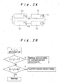
- Fig. 2A taken up as an explanatory example is a combination of the battery pack blocks 1a, 1b, and 1c, and their current sensors 4a, 4b, and 4c.
- the currents detected by the current sensors 4a, 4b, and 4c are assumed to be I 1 , I 2 , and I 3 , respectively.
- the battery pack system 10 of this embodiment is constructed as follows. As shown in Fig. 3A, the battery pack blocks 1a and 1b, as well as 1c and 1d, are connected in parallel, thereby constituting two battery pack block groups. These battery pack block groups are connected in series.
- the currents detected by the current sensors 4a, 4b, 4c, and 4d of the battery pack blocks 1a to 1d are assumed to be I 1 , I 2 , I 3 , and I 4 , respectively.
Landscapes
- Physics & Mathematics (AREA)
- General Physics & Mathematics (AREA)
- Secondary Cells (AREA)
- Charge And Discharge Circuits For Batteries Or The Like (AREA)
- Tests Of Electric Status Of Batteries (AREA)
- Testing Electric Properties And Detecting Electric Faults (AREA)
Abstract
Description
Claims (4)
- A method for detecting an abnormality in a battery pack system (10), the battery pack system being composed of a plurality of battery pack blocks (1a, 1b, 1c, 1d) connected with one another by a combination of serial connection and parallel connection, each of the battery pack blocks being constituted by connecting a plurality of cells in series,
characterized in that the method comprises:detecting a current value of each of the battery pack blocks; anddetecting an abnormality occurring in the battery pack block based on a detected current value, by using an algorithm constructed in accordance with a connection status of the battery pack blocks. - The method for detecting an abnormality in a battery pack system (10) according to claim 1, wherein,
in the battery pack system composed of a plurality of battery pack block groups connected in parallel, each of the battery pack block groups being constituted by connecting the plurality of battery pack blocks (1a, 1b, 1c, 1d) in series, when a current value difference among the battery pack block groups connected in parallel exceeds a predetermined first threshold value (t1), it is judged that an abnormality occurs in the battery pack block or in a current detecting member (4a, 4b, 4c, 4d), and, when a current value difference among the battery pack blocks connected in series exceeds a predetermined second threshold value (t2), it is judged that an abnormality occurs in the current detecting member, and
based on the judgment results, determination is made as to the abnormality of the battery pack block. - The method for detecting an abnormality in a battery pack system (10) according to claim 1, wherein,
in the battery pack system composed of a plurality of battery pack block groups connected in series, each of the battery pack block groups being constituted by connecting the plurality of battery pack blocks (1a, 1b, 1c, 1d) in parallel, when a current value difference among the battery pack blocks connected in parallel exceeds a predetermined first threshold value (t1), it is judged that an abnormality occurs in the battery pack block or in a current detecting member (4a, 4b, 4c, 4d), and, when a current value difference among the battery pack block groups connected in series exceeds the first threshold value, it is judged that an abnormality occurs in the battery pack block or in the current detecting member,
among the battery pack block groups, comparison is made as to the sum of current values in the battery pack blocks connected in parallel, and, when a difference in the sum of battery pack block's current values among the battery pack block groups exceeds a predetermined second threshold value (t2), it is judged that an abnormality occurs in the current detecting member, and
based on the judgment results, determination is made as to the abnormality of the battery pack block. - An apparatus for detecting an abnormality in a battery pack system (10), the battery pack system being composed of a plurality of battery pack blocks (1a, 1b, 1c, 1d) connected with one another by a combination of serial connection and parallel connection, each of the battery pack blocks being constituted by connecting a plurality of cells in series,
characterized in that the apparatus comprises:a current detecting member (4a, 4b, 4c, 4d) disposed in each of the battery pack blocks, for detecting a current value of the battery pack block; anda control section (5) for detecting an abnormality of the battery pack block based on a detected current value, by using an algorithm constructed in accordance with a connection status of the battery pack blocks.
Applications Claiming Priority (2)
| Application Number | Priority Date | Filing Date | Title |
|---|---|---|---|
| JP2001340661 | 2001-11-06 | ||
| JP2001340661A JP3936169B2 (en) | 2001-11-06 | 2001-11-06 | Abnormality detection method and apparatus for assembled battery system |
Publications (3)
| Publication Number | Publication Date |
|---|---|
| EP1308739A2 true EP1308739A2 (en) | 2003-05-07 |
| EP1308739A3 EP1308739A3 (en) | 2003-10-15 |
| EP1308739B1 EP1308739B1 (en) | 2010-10-13 |
Family
ID=19154820
Family Applications (1)
| Application Number | Title | Priority Date | Filing Date |
|---|---|---|---|
| EP02257615A Expired - Lifetime EP1308739B1 (en) | 2001-11-06 | 2002-11-04 | Method and apparatus for detecting abnormality in a battery pack system |
Country Status (4)
| Country | Link |
|---|---|
| US (1) | US6841291B2 (en) |
| EP (1) | EP1308739B1 (en) |
| JP (1) | JP3936169B2 (en) |
| DE (1) | DE60237954D1 (en) |
Cited By (9)
| Publication number | Priority date | Publication date | Assignee | Title |
|---|---|---|---|---|
| EP1309029A3 (en) * | 2001-11-06 | 2004-03-03 | Panasonic EV Energy Co., Ltd. | Method and apparatus for controlling cooling and detecting abnormality in battery pack system |
| EP1328052A3 (en) * | 2002-01-10 | 2004-06-02 | Panasonic EV Energy Co., Ltd. | Battery power source device, method for controlling the same, and method for providing address |
| WO2005008266A1 (en) * | 2003-07-09 | 2005-01-27 | Premium Power Corporation | Device for monitoring and charging of a selected group of battery cells |
| CN100414767C (en) * | 2004-06-02 | 2008-08-27 | 丰田自动车株式会社 | power cooling equipment |
| GB2463145A (en) * | 2008-09-03 | 2010-03-10 | Hitachi Ltd | Battery control system for block of battery cells |
| EP1990645A4 (en) * | 2006-02-27 | 2012-11-21 | Toyota Motor Co Ltd | ANORMALITY JUDGING DEVICE AND CORRESPONDING METHOD FOR CURRENT POWER SUPPLY UNIT |
| EP2618439A3 (en) * | 2011-12-22 | 2014-01-15 | Andreas Stihl AG & Co. KG | Protective circuit for a battery pack |
| WO2015185070A1 (en) * | 2014-06-02 | 2015-12-10 | Volvo Truck Corporation | A method and system for monitoring the status of battery cells |
| WO2018087094A1 (en) * | 2016-11-10 | 2018-05-17 | Tanktwo Oy | Detection of false reporting in a smart battery system |
Families Citing this family (27)
| Publication number | Priority date | Publication date | Assignee | Title |
|---|---|---|---|---|
| JP3939546B2 (en) * | 2001-12-06 | 2007-07-04 | パナソニック・イーブイ・エナジー株式会社 | Battery power device for electric vehicle |
| DE10214366B4 (en) * | 2002-03-30 | 2017-03-16 | Robert Bosch Gmbh | measuring arrangement |
| US7393598B2 (en) * | 2004-03-10 | 2008-07-01 | Hcf Partners, L.P. | Light emitting molecules and organic light emitting devices including light emitting molecules |
| CA2523240C (en) * | 2005-10-11 | 2009-12-08 | Delaware Systems Inc. | Universal battery module and controller therefor |
| JP2008292403A (en) * | 2007-05-28 | 2008-12-04 | Asahi Kasei Electronics Co Ltd | Method and device for detecting abnormality of battery pack |
| JP4753913B2 (en) * | 2007-06-27 | 2011-08-24 | 三洋電機株式会社 | Battery system |
| EP2073095A3 (en) * | 2007-12-20 | 2013-03-27 | Koninklijke KPN N.V. | Measurement device and monitoring system for processing units |
| JP5269451B2 (en) * | 2008-03-24 | 2013-08-21 | 株式会社東芝 | Battery protection device and battery protection method |
| JP5263819B2 (en) * | 2008-06-11 | 2013-08-14 | 株式会社日立製作所 | Battery monitoring system |
| JP5167521B2 (en) * | 2008-11-28 | 2013-03-21 | 旭化成エレクトロニクス株式会社 | Battery pack and electronic device using the battery pack |
| JP5817018B2 (en) * | 2008-11-28 | 2015-11-18 | 旭化成エレクトロニクス株式会社 | Current sensor |
| US20100289447A1 (en) * | 2009-05-18 | 2010-11-18 | Dobson Eric L | System and method for power management of energy storage devices |
| KR101097264B1 (en) * | 2010-01-18 | 2011-12-21 | 삼성에스디아이 주식회사 | Battery pack with built-in sensing board and power storage system using it |
| JP5619157B2 (en) * | 2010-06-17 | 2014-11-05 | 三菱電機株式会社 | Capacitive load device and abnormality detection method for capacitive load device |
| PL2666027T3 (en) | 2011-01-18 | 2024-08-19 | Tiax Llc | Differential current monitoring for parallel-connected batteries |
| US10044074B2 (en) * | 2011-03-18 | 2018-08-07 | Johnson Controls Technology Company | Battery power source control and current detection systems and methods |
| US9748784B2 (en) * | 2011-09-01 | 2017-08-29 | Echostar Technologies L.L.C. | Detecting batteries with non-uniform drain rates |
| DE102011122057A1 (en) | 2011-12-22 | 2013-06-27 | Andreas Stihl Ag & Co. Kg | Electric implement with an electrical load and a battery pack |
| DE102011122058A1 (en) | 2011-12-22 | 2013-06-27 | Andreas Stihl Ag & Co. Kg | "Back-packable battery pack" |
| DE102011121940A1 (en) | 2011-12-22 | 2013-06-27 | Andreas Stihl Ag & Co. Kg | Debalancing protection circuit for a battery pack |
| DE102011121937A1 (en) | 2011-12-22 | 2013-06-27 | Andreas Stihl Ag & Co. Kg | Protection circuit for a battery pack |
| JP5688041B2 (en) * | 2012-03-08 | 2015-03-25 | オムロンオートモーティブエレクトロニクス株式会社 | Communications system |
| JP5701279B2 (en) | 2012-12-11 | 2015-04-15 | 三菱重工業株式会社 | Charge control device, battery system, and charge control method |
| JP2016531271A (en) | 2013-03-14 | 2016-10-06 | カリフォルニア インスティチュート オブ テクノロジー | Anomaly detection of electrical and electrochemical energy units |
| WO2016100919A1 (en) | 2014-12-19 | 2016-06-23 | California Institute Of Technology | Improved systems and methods for management and monitoring of energy storage and distribution |
| EP3356836B1 (en) | 2015-10-01 | 2022-06-29 | California Institute of Technology | Systems and methods for monitoring characteristics of energy units |
| WO2020140250A1 (en) * | 2019-01-04 | 2020-07-09 | Abb Schweiz Ag | Apparatus and method for monitoring capacitor bank |
Family Cites Families (8)
| Publication number | Priority date | Publication date | Assignee | Title |
|---|---|---|---|---|
| JPH05236662A (en) | 1992-02-21 | 1993-09-10 | Matsushita Electric Ind Co Ltd | Lead-acid battery charging system |
| JP2902200B2 (en) * | 1992-03-12 | 1999-06-07 | 日本碍子株式会社 | Battery overcharge / discharge monitoring device |
| JP3331529B2 (en) * | 1993-01-29 | 2002-10-07 | キヤノン株式会社 | Power storage device and power system |
| FI99170C (en) | 1994-05-09 | 1997-10-10 | Muuntolaite Oy | Monitoring system for an accumulator |
| JP3750318B2 (en) * | 1997-11-14 | 2006-03-01 | 日産自動車株式会社 | Module charger / discharger |
| EP0982830A3 (en) * | 1998-08-21 | 2001-03-21 | Sony Corporation | Battery pack |
| JP2001095160A (en) | 1999-09-17 | 2001-04-06 | Matsushita Electric Ind Co Ltd | Abnormal battery cell detection method |
| JP2001185228A (en) * | 1999-12-24 | 2001-07-06 | Sanyo Electric Co Ltd | Electric power supply equipped with battery |
-
2001
- 2001-11-06 JP JP2001340661A patent/JP3936169B2/en not_active Expired - Fee Related
-
2002
- 2002-11-01 US US10/285,593 patent/US6841291B2/en not_active Expired - Fee Related
- 2002-11-04 EP EP02257615A patent/EP1308739B1/en not_active Expired - Lifetime
- 2002-11-04 DE DE60237954T patent/DE60237954D1/en not_active Expired - Lifetime
Cited By (17)
| Publication number | Priority date | Publication date | Assignee | Title |
|---|---|---|---|---|
| US6903534B2 (en) | 2001-11-06 | 2005-06-07 | Panasonic Ev Energy Co., Ltd. | Method and apparatus for controlling cooling and detecting abnormality in battery pack system |
| EP1309029A3 (en) * | 2001-11-06 | 2004-03-03 | Panasonic EV Energy Co., Ltd. | Method and apparatus for controlling cooling and detecting abnormality in battery pack system |
| EP1328052A3 (en) * | 2002-01-10 | 2004-06-02 | Panasonic EV Energy Co., Ltd. | Battery power source device, method for controlling the same, and method for providing address |
| US7939190B2 (en) | 2003-07-09 | 2011-05-10 | Premium Power Corporation | Systems and methods for selective cell and/or stack control in a flowing electrolyte battery |
| WO2005008266A1 (en) * | 2003-07-09 | 2005-01-27 | Premium Power Corporation | Device for monitoring and charging of a selected group of battery cells |
| AU2004258144B2 (en) * | 2003-07-09 | 2009-12-03 | Largo Clean Energy Corp. | Device for monitoring and charging of a selected group of battery cells |
| US9325021B2 (en) | 2003-07-09 | 2016-04-26 | Vionx Energy Corporation | Systems and methods for selective cell and/or stack control in a flowing electrolyte battery |
| US8697267B2 (en) | 2003-07-09 | 2014-04-15 | Premium Power Corporation | Systems and methods for selective cell and/or stack control in a flowing electrolyte battery |
| CN100414767C (en) * | 2004-06-02 | 2008-08-27 | 丰田自动车株式会社 | power cooling equipment |
| EP1990645A4 (en) * | 2006-02-27 | 2012-11-21 | Toyota Motor Co Ltd | ANORMALITY JUDGING DEVICE AND CORRESPONDING METHOD FOR CURRENT POWER SUPPLY UNIT |
| GB2463145B (en) * | 2008-09-03 | 2010-10-13 | Hitachi Ltd | A battery control system and a method for battery control |
| GB2463145A (en) * | 2008-09-03 | 2010-03-10 | Hitachi Ltd | Battery control system for block of battery cells |
| EP2618439A3 (en) * | 2011-12-22 | 2014-01-15 | Andreas Stihl AG & Co. KG | Protective circuit for a battery pack |
| WO2015185070A1 (en) * | 2014-06-02 | 2015-12-10 | Volvo Truck Corporation | A method and system for monitoring the status of battery cells |
| US10151801B2 (en) | 2014-06-02 | 2018-12-11 | Volvo Truck Corporation | Method and system for monitoring the status of battery cells |
| WO2018087094A1 (en) * | 2016-11-10 | 2018-05-17 | Tanktwo Oy | Detection of false reporting in a smart battery system |
| US11489354B2 (en) | 2016-11-10 | 2022-11-01 | Tanktwo Oy | Detection of false reporting in a smart battery system |
Also Published As
| Publication number | Publication date |
|---|---|
| JP3936169B2 (en) | 2007-06-27 |
| EP1308739A3 (en) | 2003-10-15 |
| US6841291B2 (en) | 2005-01-11 |
| DE60237954D1 (en) | 2010-11-25 |
| JP2003142165A (en) | 2003-05-16 |
| EP1308739B1 (en) | 2010-10-13 |
| US20030087147A1 (en) | 2003-05-08 |
Similar Documents
| Publication | Publication Date | Title |
|---|---|---|
| EP1308739A2 (en) | Method and apparatus for detecting abnormality in a battery pack | |
| EP1309029B1 (en) | Method and apparatus for controlling cooling and detecting abnormality in battery pack system | |
| US6444350B1 (en) | Battery unit which can detect an abnormal temperature rise of at least one of a plurality of cells | |
| US7129707B2 (en) | Apparatus for judging state of assembled battery | |
| KR101792489B1 (en) | Classification of electric contacting between two connecting elements | |
| US9267998B2 (en) | Protective circuit for a rechargeable battery pack | |
| CN103250300B (en) | Battery system and method for determining battery module voltage | |
| CN106772082B (en) | Voltage acquisition line disconnection detection method for single battery | |
| JP4260121B2 (en) | Power supply | |
| US8013618B2 (en) | Voltage detection apparatus | |
| US20120098547A1 (en) | Semiconductor circuit, semiconductor device, method of diagnosing abnormality of wire, and computer readable storage medium | |
| CN116391132A (en) | Detection method for detecting defects of a module group of batteries | |
| JP5160024B2 (en) | Battery module | |
| WO2007089047A1 (en) | Secondary cell monitoring device | |
| JP2003061254A (en) | Voltage detector for battery pack | |
| KR102324968B1 (en) | System and method for diagnosing the connectivity of fuses, bms including a system for diagnosing the connectivity of fuses | |
| KR102294267B1 (en) | Cell Sensing Circuit Inspection Apparatus For Electrical Vehicle Battery Or Fuel Cell Vehicle Stack, And Inspection Method Thereof | |
| JP4533357B2 (en) | Voltage measuring device | |
| JP2006073362A (en) | Power supply for vehicle | |
| JP2013235689A (en) | Current sensor abnormality detecting device and method | |
| JP2006197790A (en) | Power supply | |
| JP2022182565A (en) | voltage detector | |
| JPH1021965A (en) | Battery battery abnormality judgment device | |
| JP4116756B2 (en) | Abnormality detection device for battery pack | |
| GB2354587A (en) | Detecting abnormal temperature rise in cells of a battery |
Legal Events
| Date | Code | Title | Description |
|---|---|---|---|
| PUAI | Public reference made under article 153(3) epc to a published international application that has entered the european phase |
Free format text: ORIGINAL CODE: 0009012 |
|
| AK | Designated contracting states |
Designated state(s): AT BE BG CH CY CZ DE DK EE ES FI FR GB GR IE IT LI LU MC NL PT SE SK TR |
|
| AX | Request for extension of the european patent |
Extension state: AL LT LV MK RO SI |
|
| PUAL | Search report despatched |
Free format text: ORIGINAL CODE: 0009013 |
|
| AK | Designated contracting states |
Kind code of ref document: A3 Designated state(s): AT BE BG CH CY CZ DE DK EE ES FI FR GB GR IE IT LI LU MC NL PT SE SK TR |
|
| AX | Request for extension of the european patent |
Extension state: AL LT LV MK RO SI |
|
| 17P | Request for examination filed |
Effective date: 20040331 |
|
| AKX | Designation fees paid |
Designated state(s): DE FR GB |
|
| 17Q | First examination report despatched |
Effective date: 20061211 |
|
| GRAP | Despatch of communication of intention to grant a patent |
Free format text: ORIGINAL CODE: EPIDOSNIGR1 |
|
| GRAS | Grant fee paid |
Free format text: ORIGINAL CODE: EPIDOSNIGR3 |
|
| GRAA | (expected) grant |
Free format text: ORIGINAL CODE: 0009210 |
|
| AK | Designated contracting states |
Kind code of ref document: B1 Designated state(s): DE FR GB |
|
| REG | Reference to a national code |
Ref country code: GB Ref legal event code: FG4D |
|
| REF | Corresponds to: |
Ref document number: 60237954 Country of ref document: DE Date of ref document: 20101125 Kind code of ref document: P |
|
| PGFP | Annual fee paid to national office [announced via postgrant information from national office to epo] |
Ref country code: GB Payment date: 20101123 Year of fee payment: 9 |
|
| PLBE | No opposition filed within time limit |
Free format text: ORIGINAL CODE: 0009261 |
|
| STAA | Information on the status of an ep patent application or granted ep patent |
Free format text: STATUS: NO OPPOSITION FILED WITHIN TIME LIMIT |
|
| 26N | No opposition filed |
Effective date: 20110714 |
|
| REG | Reference to a national code |
Ref country code: DE Ref legal event code: R097 Ref document number: 60237954 Country of ref document: DE Effective date: 20110714 |
|
| GBPC | Gb: european patent ceased through non-payment of renewal fee |
Effective date: 20111104 |
|
| PG25 | Lapsed in a contracting state [announced via postgrant information from national office to epo] |
Ref country code: GB Free format text: LAPSE BECAUSE OF NON-PAYMENT OF DUE FEES Effective date: 20111104 |
|
| PGFP | Annual fee paid to national office [announced via postgrant information from national office to epo] |
Ref country code: DE Payment date: 20141114 Year of fee payment: 13 |
|
| PGFP | Annual fee paid to national office [announced via postgrant information from national office to epo] |
Ref country code: FR Payment date: 20141118 Year of fee payment: 13 |
|
| REG | Reference to a national code |
Ref country code: DE Ref legal event code: R119 Ref document number: 60237954 Country of ref document: DE |
|
| REG | Reference to a national code |
Ref country code: FR Ref legal event code: ST Effective date: 20160729 |
|
| PG25 | Lapsed in a contracting state [announced via postgrant information from national office to epo] |
Ref country code: DE Free format text: LAPSE BECAUSE OF NON-PAYMENT OF DUE FEES Effective date: 20160601 |
|
| PG25 | Lapsed in a contracting state [announced via postgrant information from national office to epo] |
Ref country code: FR Free format text: LAPSE BECAUSE OF NON-PAYMENT OF DUE FEES Effective date: 20151130 |