EP1308679A2 - Ejector for ejector cycle system - Google Patents
Ejector for ejector cycle system Download PDFInfo
- Publication number
- EP1308679A2 EP1308679A2 EP02024426A EP02024426A EP1308679A2 EP 1308679 A2 EP1308679 A2 EP 1308679A2 EP 02024426 A EP02024426 A EP 02024426A EP 02024426 A EP02024426 A EP 02024426A EP 1308679 A2 EP1308679 A2 EP 1308679A2
- Authority
- EP
- European Patent Office
- Prior art keywords
- refrigerant
- passage
- ejector
- nozzle
- gas
- Prior art date
- Legal status (The legal status is an assumption and is not a legal conclusion. Google has not performed a legal analysis and makes no representation as to the accuracy of the status listed.)
- Ceased
Links
Images




Classifications
-
- F—MECHANICAL ENGINEERING; LIGHTING; HEATING; WEAPONS; BLASTING
- F04—POSITIVE - DISPLACEMENT MACHINES FOR LIQUIDS; PUMPS FOR LIQUIDS OR ELASTIC FLUIDS
- F04F—PUMPING OF FLUID BY DIRECT CONTACT OF ANOTHER FLUID OR BY USING INERTIA OF FLUID TO BE PUMPED; SIPHONS
- F04F5/00—Jet pumps, i.e. devices in which flow is induced by pressure drop caused by velocity of another fluid flow
- F04F5/02—Jet pumps, i.e. devices in which flow is induced by pressure drop caused by velocity of another fluid flow the inducing fluid being liquid
- F04F5/04—Jet pumps, i.e. devices in which flow is induced by pressure drop caused by velocity of another fluid flow the inducing fluid being liquid displacing elastic fluids
-
- F—MECHANICAL ENGINEERING; LIGHTING; HEATING; WEAPONS; BLASTING
- F25—REFRIGERATION OR COOLING; COMBINED HEATING AND REFRIGERATION SYSTEMS; HEAT PUMP SYSTEMS; MANUFACTURE OR STORAGE OF ICE; LIQUEFACTION SOLIDIFICATION OF GASES
- F25B—REFRIGERATION MACHINES, PLANTS OR SYSTEMS; COMBINED HEATING AND REFRIGERATION SYSTEMS; HEAT PUMP SYSTEMS
- F25B41/00—Fluid-circulation arrangements
-
- F—MECHANICAL ENGINEERING; LIGHTING; HEATING; WEAPONS; BLASTING
- F25—REFRIGERATION OR COOLING; COMBINED HEATING AND REFRIGERATION SYSTEMS; HEAT PUMP SYSTEMS; MANUFACTURE OR STORAGE OF ICE; LIQUEFACTION SOLIDIFICATION OF GASES
- F25B—REFRIGERATION MACHINES, PLANTS OR SYSTEMS; COMBINED HEATING AND REFRIGERATION SYSTEMS; HEAT PUMP SYSTEMS
- F25B41/00—Fluid-circulation arrangements
- F25B41/30—Expansion means; Dispositions thereof
-
- F—MECHANICAL ENGINEERING; LIGHTING; HEATING; WEAPONS; BLASTING
- F25—REFRIGERATION OR COOLING; COMBINED HEATING AND REFRIGERATION SYSTEMS; HEAT PUMP SYSTEMS; MANUFACTURE OR STORAGE OF ICE; LIQUEFACTION SOLIDIFICATION OF GASES
- F25B—REFRIGERATION MACHINES, PLANTS OR SYSTEMS; COMBINED HEATING AND REFRIGERATION SYSTEMS; HEAT PUMP SYSTEMS
- F25B2309/00—Gas cycle refrigeration machines
- F25B2309/06—Compression machines, plants or systems characterised by the refrigerant being carbon dioxide
- F25B2309/061—Compression machines, plants or systems characterised by the refrigerant being carbon dioxide with cycle highest pressure above the supercritical pressure
-
- F—MECHANICAL ENGINEERING; LIGHTING; HEATING; WEAPONS; BLASTING
- F25—REFRIGERATION OR COOLING; COMBINED HEATING AND REFRIGERATION SYSTEMS; HEAT PUMP SYSTEMS; MANUFACTURE OR STORAGE OF ICE; LIQUEFACTION SOLIDIFICATION OF GASES
- F25B—REFRIGERATION MACHINES, PLANTS OR SYSTEMS; COMBINED HEATING AND REFRIGERATION SYSTEMS; HEAT PUMP SYSTEMS
- F25B2341/00—Details of ejectors not being used as compression device; Details of flow restrictors or expansion valves
- F25B2341/001—Ejectors not being used as compression device
- F25B2341/0012—Ejectors with the cooled primary flow at high pressure
-
- F—MECHANICAL ENGINEERING; LIGHTING; HEATING; WEAPONS; BLASTING
- F25—REFRIGERATION OR COOLING; COMBINED HEATING AND REFRIGERATION SYSTEMS; HEAT PUMP SYSTEMS; MANUFACTURE OR STORAGE OF ICE; LIQUEFACTION SOLIDIFICATION OF GASES
- F25B—REFRIGERATION MACHINES, PLANTS OR SYSTEMS; COMBINED HEATING AND REFRIGERATION SYSTEMS; HEAT PUMP SYSTEMS
- F25B2500/00—Problems to be solved
- F25B2500/01—Geometry problems, e.g. for reducing size
-
- F—MECHANICAL ENGINEERING; LIGHTING; HEATING; WEAPONS; BLASTING
- F25—REFRIGERATION OR COOLING; COMBINED HEATING AND REFRIGERATION SYSTEMS; HEAT PUMP SYSTEMS; MANUFACTURE OR STORAGE OF ICE; LIQUEFACTION SOLIDIFICATION OF GASES
- F25B—REFRIGERATION MACHINES, PLANTS OR SYSTEMS; COMBINED HEATING AND REFRIGERATION SYSTEMS; HEAT PUMP SYSTEMS
- F25B9/00—Compression machines, plants or systems, in which the refrigerant is air or other gas of low boiling point
- F25B9/002—Compression machines, plants or systems, in which the refrigerant is air or other gas of low boiling point characterised by the refrigerant
- F25B9/008—Compression machines, plants or systems, in which the refrigerant is air or other gas of low boiling point characterised by the refrigerant the refrigerant being carbon dioxide
Definitions
- the present invention relates to an ejector used for an ejector cycle system, which sucks gas refrigerant by a high-speed refrigerant flow jetted from a nozzle.
- an ejector in an ejector cycle system described in JP-U-57-76300, as shown in FIG. 9, an ejector includes a nozzle 40 for converting a pressure energy of high-pressure refrigerant from a radiator to a speed energy, a mixing portion 42 in which gas refrigerant evaporated in an evaporator is sucked by a high-speed refrigerant flow jetted from the nozzle 41, and a diffuser 43 in which the speed energy is converted to the pressure energy so that the pressure of refrigerant is increased while refrigerant discharged from the nozzle 40 and the gas refrigerant from the evaporator are mixed.
- the nozzle 40 has a taper portion 41 at an inlet side, and the diffuser 43 is formed into a taper shape. Because each inner wall of the taper portion 41 and the diffuser 43 is formed into a conical taper shape, it is difficult to form the hole by using a simple drill. Generally, electrical discharge machining or wire cutting is necessary for forming the hole in the taper portion 41 and the diffuser 43. Accordingly, it is difficult to reduce manufacturing process and product cost.
- a taper angel of the taper portion 411 is set at a relative small angle for preventing a large disturbance of the refrigerant flow in the nozzle 40. Therefore, an axial dimension of the nozzle 40 becomes longer.
- an ejector used for an ejector cycle system includes a nozzle for decompressing high-pressure refrigerant flowing from a radiator by converting a pressure energy of the high-pressure refrigerant to a speed energy, and a mixing portion in which gas refrigerant evaporated in an evaporator is sucked by a flow of refrigerant jetted from the nozzle, to be mixed with the refrigerant jetted from the nozzle.
- the nozzle has a first refrigerant passage, a second refrigerant passage, and a third refrigerant passage in this order in a refrigerant flow direction from a refrigerant inlet toward a refrigerant outlet of the nozzle.
- the first refrigerant passage, the second refrigerant passage and the third refrigerant passage have cylindrical shapes, respectively, each having a constant passage diameter, and the passage diameter of the first refrigerant passage is larger than the passage diameter of the second refrigerant passage. Accordingly, the first refrigerant passage, the second refrigerant passage and the third refrigerant passage can be readily manufactured by a simple cutting method such as drilling. Thus, product cost of the ejector can be reduced.
- the passage diameter of the second refrigerant passage can be made smaller than the passage diameter of the third refrigerant passage.
- the passage diameter of the second refrigerant passage can be made equal to the passage diameter of the third refrigerant passage.
- the passage diameter of the second refrigerant passage can be larger than the passage diameter of the third refrigerant passage.
- the mixing portion has a cylindrical passage having a constant passage diameter.
- the mixing portion can be readily formed by the simple cutting method such as drilling.
- a nozzle in an ejector for an ejector cycle system, includes a taper portion in which a passage sectional area is reduced toward a downstream refrigerant side to have a throttle portion at which the passage sectional area becomes smallest, and an outlet passage portion connected to the throttle portion at a refrigerant downstream side. Further, the taper portion has a taper angle at a refrigerant inlet side, that is larger than that at a side of the throttle portion. Accordingly, the flow speed of refrigerant can be rapidly increased, and an axial dimension of the nozzle can be relatively reduced. Thus, the axial dimension of the ejector can be effectively reduced.
- the taper angle of the taper portion can be changed stepwise, and the outlet passage portion of the nozzle can be formed into a cylindrical shape having a constant passage diameter.
- the present invention is typically applied to an ejector cycle system for a vehicle air conditioner.
- a compressor 100 is driven by a driving source such as a vehicle engine (not shown) to suck and compress refrigerant.
- a radiator 200 i.e., high-pressure side heat exchanger
- refrigerant discharged from the compressor 100 is heat-exchanged with air (outside air) outside a passenger compartment, to be cooled.
- evaporator 300 i.e., low-pressure side heat exchanger
- liquid refrigerant in the ejector cycle system is heat-exchanged with air to be blown into a passenger compartment so that air passing through the evaporator 300 is cooled.
- An ejector 400 decompresses and expands high-pressure refrigerant flowing from the radiator 200 to suck therein gas refrigerant evaporated in the evaporator 300, and converts an expansion energy to a pressure energy to increase the pressure of refrigerant to be sucked into the compressor 100.
- the refrigerant from the ejector 400 flows into a gas-liquid separator 500, and is separated into gas refrigerant and liquid refrigerant in the gas-liquid separator 500.
- the separated gas refrigerant in the gas-liquid separator 500 is sucked into the compressor 100, and the separated liquid refrigerant in the gas-liquid separator is sucked to a side of the evaporator 300.
- the gas-liquid separator 500 is connected to the evaporator 300 through a refrigerant passage.
- a flow amount control valve such as a capillary tube, a fixed throttle and a variable throttle can be provided.
- the ejector 400 includes a nozzle 410 and a mixing portion 420.
- the nozzle 410 decompresses and expands the high-pressure refrigerant flowing from the radiator 200 by converting a pressure energy (pressure head) of the refrigerant to a speed energy (speed head) thereof.
- Gas refrigerant evaporated in the evaporator 300 is sucked into the mixing portion 420 by a high-speed refrigerant flow jetted from the nozzle 410, and is mixed with the refrigerant jetted from the nozzle 410 in the mixing portion 420.
- the nozzle 410 is constructed to have a first refrigerant passage 411, a second refrigerant passage 412 and a third refrigerant passage 413, in this order from a refrigerant inlet toward a refrigerant outlet.
- the first refrigerant passage 411, the second refrigerant passage 412 and the third refrigerant passage 413 are formed into cylindrical shapes having predetermined passage diameters D1, D2, D3, respectively.
- the passage diameter D1 of the first refrigerant passage 411 is larger than the passage diameter D2 of the second refrigerant passage 412 and the passage diameter of the third refrigerant passage 413.
- the passage diameter D2 of the second refrigerant passage 412 is smaller than the passage diameter D3 of the third refrigerant passage 413.
- the ejector 400 is made of a metal material such as a stainless steel, copper and aluminum. After performing a die-casting molding using the metal material, cutting such as drilling is performed for forming the refrigerant passages 411-413 and the mixing portion 420, so that the ejector 400 is manufactured.
- the ejector cycle system When the compressor 100 starts operation, the gas refrigerant from the gas-liquid separator 500 is sucked into the compressor 100, and the compressed refrigerant is discharged from the compressor 100 into the radiator 200. Refrigerant cooled in the radiator 200 is decompressed in the nozzle 410 of the ejector 400, and gas refrigerant evaporated in the evaporator 300 is sucked into the ejector 400. That is, in the first embodiment, the ejector 400 is also used as a pump for circulating refrigerant between the gas-liquid separator 500 and the evaporator 300.
- the refrigerant sucked from the evaporator 300 and the refrigerant jetted from the nozzle 410 are mixed in the mixing portion 420, and thereafter flows into the gas-liquid separator 500.
- the mixing portion 420 the refrigerant jet flow jetted from the nozzle 410 and the refrigerant suction flow sucked from the evaporator 300 are mixed so that the sum of the kinetic amount of the driving flow refrigerant (jet flow refrigerant) from the nozzle 410 and the kinetic amount of the suction flow refrigerant from the evaporator 300 are maintained, and the refrigerant pressure is increased in the mixing portion 420.
- the mixing portion 420 functions as a pressure increasing portion in which the pressure of refrigerant to be sucked into the compressor 100 is increased.
- liquid refrigerant from the gas-liquid separator 500 flows into the evaporator 300 to be evaporated by absorbing heat from air to be blown into the passenger compartment.
- FIG. 3 is a simulation result showing a relationship between a refrigerant flow speed (relative speed) from the refrigerant outlet of the nozzle 410 to the refrigerant outlet of the mixing portion 420, and a radial position in a radial direction from a center in a refrigerant passage cross-section of the ejector 400.
- the simulation of FIG. 3 is performed, assuming that the refrigerant flow speed distribution (gas flow speed distribution) is symmetrical relative to a center axial line, and assuming that the refrigerant flow speed at the outlet of the nozzle 410 is 1.
- the refrigerant flow speed distribution gas flow speed distribution
- A indicates a jet-flow gas refrigerant flowing from the nozzle 410
- C indicates a suction gas refrigerant (suction flow gas) sucked from the evaporator 300.
- the flow speed of the jet-flow gas refrigerant discharged from the nozzle 410 becomes lower while the jet-flow gas refrigerant sucks and accelerates refrigerant from the evaporator 300. Therefore, at a refrigerant outlet side of the mixing portion 420, the flow speed decrease of the jet-flow gas refrigerant is nearly finished as shown by B in FIG. 3.
- FIG. 4 shows the operation of the ejector cycle.
- the reference numbers C1-C9 indicate operation positions in the ejector cycle system in FIG. 1.
- FIG. 4 shows an ideal state where a pressure loss generated in refrigerant pipes connecting the compressor 100, the radiator 200, the evaporator 300, the ejector 400 and the gas-liquid separator 500 is omitted.
- the nozzle 410 is formed to have the first, second and third refrigerant passages 411, 412, 413 having certain passage diameters in cross section. That is, each of the refrigerant passages 411, 412, 413 has a simple cylindrical shape, the nozzle 410 can be readily manufactured by simple cutting such as drilling. Accordingly, the ejector 400 can be manufactured in low cost.
- the refrigerant passages 411, 412, 413 are formed into the cylindrical shapes having different passage diameters, a step portion is formed between adjacent two of the refrigerant passages 411, 412, 413. Therefore, the refrigerant flow is disturbed in the step portion, and a conversion efficiency converting the pressure energy to the speed energy of refrigerant is decreased as compared with a case without the step portion.
- the ejector 400 can be manufactured in low cost while actual consumed power in the compressor 100 can be reduced as compared with the vapor-compression refrigerant cycle.
- the first, second and third refrigerant passages 411-413 are formed to have a passage diameter ratio (D1:D2:D3) of 20:2:3, for example.
- the passage diameter D3 of the third refrigerant passage 413 is made larger than the passage diameter D2 of the second refrigerant passage 412.
- the passage diameter D3 of the third refrigerant passage 413 can be made equal to the passage diameter D2 of the second refrigerant passage 412.
- the passage diameter D3 of the third refrigerant passage 413 can be made smaller than the passage diameter D2 of the second refrigerant passage 412.
- fluorocarbon (flon) or carbon dioxide can be used as the refrigerant, for example.
- fluorocarbon fluorocarbon
- carbon dioxide used as the refrigerant in the ejector cycle system
- the refrigerant pressure at the high-pressure side is lower than the critical pressure of the refrigerant.
- the refrigerant pressure at the high-pressure side is becomes higher than the critical pressure of the refrigerant.
- FIG. 5 the sectional shapes of the refrigerant passages 411-413 are changed in an ejector 400 for the ejector cycle system.
- a first refrigerant passage (taper portion) 411 is tapered so that a passage sectional area of the taper portion 411 is reduced gradually from the refrigerant inlet toward a refrigerant downstream side.
- the passage sectional area of the taper portion 411 is reduced and becomes smallest at a second refrigerant passage (throttle portion) 412.
- a third refrigerant passage (outlet passage portion) 413 connected to the throttle portion 412 is tapered so that the passage sectional area of the third refrigerant passage 413 is gradually increased toward the refrigerant outlet of the outlet passage portion 413. That is, in the second embodiment, as the nozzle 410, a divergent nozzle (De Laval Nozzle) is used.
- the throttle portion 412 having a smallest passage diameter is formed into a throttle like with a short axial dimension. However, the axial dimension of the throttle portion 412 can be adjusted to be longer.
- the taper portion 411 is a passage-area reducing portion in which the passage sectional area is reduced from the refrigerant inlet toward the throttle portion 412, and the outlet passage portion 413 is a passage-area increasing portion in which the passage sectional area is increased from the throttle portion 412 toward the refrigerant outlet.
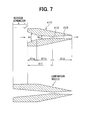
- the taper portion 411 is formed into a two-step taper shape to have a first taper portion 411a at the refrigerant inlet side, and a second taper portion 411b at the side of the throttle portion 412.
- a taper angle ⁇ 1 of the first taper portion 411a is set larger than a taper angle ⁇ 2 of the second taper portion 411b, in the taper portion 411 of the nozzle 410.
- FIG. 6 shows a refrigerant flow speed in a comparison nozzle having a constant taper angle in the taper portion.
- the flow speed of refrigerant around the inlet portion of the taper portion is rapidly increased, and thereafter, the flow speed is relatively slowly increased. After the throttle portion, the flow speed is slightly increased in the outlet passage portion.
- the taper portion (passage-area reducing portion) 411 is formed to have the first and second taper portions 411a, 411b, so that the refrigerant flow speed can be more rapidly increased in the nozzle 410. Further, the taper angle ⁇ 1 of the first taper portion 411a is set larger than the taper angle ⁇ 2 of the second taper portion 411b, so that the refrigerant flow speed can be effectively increased. Accordingly, even when the sectional area of the throttle portion 412 is set equal to that of the comparison nozzle, the axial dimension of the nozzle 410 of the second embodiment can be reduced as compared with the comparison nozzle.
- the taper angle of the taper portion 411 is changed in two steps having two different taper angles.
- the taper portion 411 of the nozzle 410 can be formed into a taper shape having plural steps more than two.
- the outlet passage portion 413 (third refrigerant passage) of the nozzle 410 is formed into the taper shape where the passage sectional area is increased from the throttle portion 412 toward the refrigerant outlet.
- the refrigerant flow speed in the nozzle 410 is slightly increased after passing through the throttle portion 412. Therefore, in the second embodiment, as shown in FIG. 8, the outlet passage portion 413 of the nozzle 410 can be formed into a cylindrical shape having a constant passage diameter.
- the constant passage diameter of the outlet passage portion 413 can be set equal to that of the throttle portion 412.
- the nozzle 410 of the second embodiment can be used for an ejector cycle system where fluorocarbon (flon) and carbon dioxide can be used as the refrigerant, for example.
- a taper-shaped diffuser for increasing the refrigerant pressure by converting the speed energy to the pressure energy can be provided at the refrigerant outlet of the mixing portion 420.
- the ejector cycle system is used for a vehicle air conditioner.
- the ejector cycle system can be used for an air conditioner for an any compartment, a cooling unit, or a heating unit using a heat pump.
Landscapes
- Engineering & Computer Science (AREA)
- Physics & Mathematics (AREA)
- Mechanical Engineering (AREA)
- General Engineering & Computer Science (AREA)
- Thermal Sciences (AREA)
- Fluid Mechanics (AREA)
- Jet Pumps And Other Pumps (AREA)
- Nozzles (AREA)
Abstract
Description
Claims (10)
- An ejector (400) for an ejector cycle system including a compressor (100), a radiator (200), an evaporator (300) and a gas-liquid separator (500), the ejector cycle system being constructed such that gas refrigerant separated in the gas-liquid separator is supplied to a suction side of the compressor and liquid refrigerant separated in the gas-liquid separator is supplied to the evaporator, the ejector comprising:a nozzle (410) for decompressing high-pressure refrigerant flowing from the radiator by converting a pressure energy of the high-pressure refrigerant to a speed energy; anda mixing portion (420) in which gas refrigerant evaporated in the evaporator is sucked by a flow of refrigerant jetted from the nozzle, to be mixed with the refrigerant jetted from the nozzle, wherein:the nozzle has a first refrigerant passage (411), a second refrigerant passage (412), and a third refrigerant passage (413) in this order in a refrigerant flow direction from a refrigerant inlet toward a refrigerant outlet of the nozzle;the first refrigerant passage, the second refrigerant passage and the third refrigerant passage have cylindrical shapes, respectively, each having a constant passage diameter; andthe passage diameter (D1) of the first refrigerant passage (411) is larger than the passage diameter (D2) of the second refrigerant passage (412).
- The ejector according to claim 1, wherein the passage diameter (D2) of the second refrigerant passage (412) is smaller than the passage diameter (D3) of the third refrigerant passage (413).
- The ejector according to claim 1, wherein the passage diameter (D2) of the second refrigerant passage (412) is equal to the passage diameter (D3) of the third refrigerant passage (413).
- The ejector according to claim 1, wherein the passage diameter (D2) of the second refrigerant passage (412) is larger than the passage diameter (D3) of the third refrigerant passage (413).
- The ejector according to claim 1, wherein a ratio of the passage diameters of the first refrigerant passage, the second refrigerant passage and the third refrigerant passage is approximately 20: 2: 3.
- The ejector according to any one of claims 1-5, wherein the mixing portion (420) has a cylindrical passage having a constant passage diameter.
- An ejector (400) for an ejector cycle system including a compressor (100), a radiator (200), an evaporator (300) and a gas-liquid separator (500), the ejector cycle system being constructed such that gas refrigerant separated in the gas-liquid separator is supplied to a suction side of the compressor and liquid refrigerant separated in the gas-liquid separator is supplied to the evaporator, the ejector comprising:a nozzle (410) for decompressing high-pressure refrigerant flowing from the radiator by converting a pressure energy of the high-pressure refrigerant to a speed energy; anda pressure-increasing portion (420) in which the speed energy is converted to the pressure energy so that the pressure of refrigerant is increased while refrigerant jetted from the nozzle and gas refrigerant from the evaporator are mixed, wherein:the nozzle includes a taper portion (411) in which a passage sectional area is reduced toward a downstream refrigerant side to have a throttle portion (412) at which the passage sectional area becomes smallest, and an outlet passage portion (413) connected to the throttle portion at a refrigerant downstream side; andthe taper portion (411) has a taper angle at a refrigerant inlet side, that is larger than that at a side of the throttle portion (412).
- The ejector according to claim 7, wherein the taper portion (411) has a taper angle that is changed stepwise.
- The ejector according to any one of claims 7 and 8, wherein the outlet passage portion (413) of the nozzle has a cylindrical shape having a constant passage diameter.
- The ejector according to any one of claims 7 and 8, wherein the outlet passage portion (413) of the nozzle is tapered such that a passage sectional area is gradually increased from the throttle portion (412) toward the refrigerant downstream side.
Applications Claiming Priority (2)
| Application Number | Priority Date | Filing Date | Title |
|---|---|---|---|
| JP2001332747A JP3903766B2 (en) | 2001-10-30 | 2001-10-30 | Ejector |
| JP2001332747 | 2001-10-30 |
Publications (2)
| Publication Number | Publication Date |
|---|---|
| EP1308679A2 true EP1308679A2 (en) | 2003-05-07 |
| EP1308679A3 EP1308679A3 (en) | 2003-10-08 |
Family
ID=19148122
Family Applications (1)
| Application Number | Title | Priority Date | Filing Date |
|---|---|---|---|
| EP02024426A Ceased EP1308679A3 (en) | 2001-10-30 | 2002-10-29 | Ejector for ejector cycle system |
Country Status (5)
| Country | Link |
|---|---|
| US (1) | US6604379B2 (en) |
| EP (1) | EP1308679A3 (en) |
| JP (1) | JP3903766B2 (en) |
| CN (2) | CN2583578Y (en) |
| BR (1) | BR0207604A (en) |
Cited By (1)
| Publication number | Priority date | Publication date | Assignee | Title |
|---|---|---|---|---|
| EP1705436A3 (en) * | 2005-03-04 | 2007-10-24 | Tgk Company, Ltd. | Expansion valve and method for manufacturing the same |
Families Citing this family (17)
| Publication number | Priority date | Publication date | Assignee | Title |
|---|---|---|---|---|
| JP3928470B2 (en) * | 2002-04-26 | 2007-06-13 | 株式会社デンソー | Air conditioner for vehicles |
| JP3928471B2 (en) * | 2002-04-26 | 2007-06-13 | 株式会社デンソー | Air conditioner for vehicles |
| JP4200780B2 (en) * | 2003-02-14 | 2008-12-24 | 株式会社デンソー | Vapor compression refrigerator |
| US6918266B2 (en) * | 2003-04-21 | 2005-07-19 | Denso Corporation | Ejector for vapor-compression refrigerant cycle |
| JP4114554B2 (en) * | 2003-06-18 | 2008-07-09 | 株式会社デンソー | Ejector cycle |
| JP2005009774A (en) * | 2003-06-19 | 2005-01-13 | Denso Corp | Ejector cycle |
| JP4049063B2 (en) * | 2003-09-10 | 2008-02-20 | 株式会社デンソー | Coaxiality measuring method and coaxiality measuring device |
| JP4539499B2 (en) * | 2004-11-09 | 2010-09-08 | 株式会社デンソー | Vibration processing apparatus and vibration processing method |
| JP4929936B2 (en) * | 2006-09-07 | 2012-05-09 | 株式会社デンソー | Ejector and ejector refrigeration cycle |
| US20100150742A1 (en) * | 2008-12-16 | 2010-06-17 | Jan Vetrovec | Reconfigurable jet pump |
| JP5575225B2 (en) | 2010-03-31 | 2014-08-20 | 三菱電機株式会社 | Ejector, driving fluid foaming method, and refrigeration cycle apparatus |
| JP5821709B2 (en) * | 2012-03-07 | 2015-11-24 | 株式会社デンソー | Ejector |
| CN102659196A (en) * | 2012-05-28 | 2012-09-12 | 天津壹帆水务有限公司 | Energy-saving evaporation process and system thereof |
| JP6090104B2 (en) | 2012-12-13 | 2017-03-08 | 株式会社デンソー | Ejector |
| CN102996530B (en) * | 2012-12-19 | 2016-03-02 | 宁波思进机械股份有限公司 | Vortex type negative-pressure liquid suction device |
| CN103148649B (en) * | 2013-03-27 | 2015-03-04 | 上海理工大学 | Ejector design method for vapor compression refrigeration circulating system |
| CN111608963A (en) * | 2020-06-02 | 2020-09-01 | 江苏惠生流体设备有限公司 | Intelligent ejector convenient to maintain |
Family Cites Families (12)
| Publication number | Priority date | Publication date | Assignee | Title |
|---|---|---|---|---|
| US2859596A (en) * | 1955-06-01 | 1958-11-11 | Girton Mfg Company Inc | Refrigeration system |
| US3838002A (en) * | 1972-07-21 | 1974-09-24 | Gen Electric | Jet pump for nuclear reactor |
| SE7511629L (en) * | 1974-10-21 | 1976-04-22 | Gen Electric | NOZZLE FOR STRAL PUMP |
| US4187695A (en) * | 1978-11-07 | 1980-02-12 | Virginia Chemicals Inc. | Air-conditioning system having recirculating and flow-control means |
| JPS5776300A (en) | 1980-10-28 | 1982-05-13 | Kurabo Ind Ltd | Apparatus for transporting work liquid under constant pressure |
| JP2801598B2 (en) * | 1988-02-01 | 1998-09-21 | 株式会社東芝 | Reactor emergency core cooling system |
| DE4036854C1 (en) * | 1990-11-19 | 1992-05-21 | Thermal-Werke, Waerme-, Kaelte-, Klimatechnik Gmbh, 6832 Hockenheim, De | |
| JP3158656B2 (en) * | 1992-06-16 | 2001-04-23 | 株式会社デンソー | Ejector |
| US5713212A (en) * | 1997-02-07 | 1998-02-03 | Mcdonnell Douglas Corporation | Apparatus and method for generating air stream |
| RU2107841C1 (en) * | 1997-04-21 | 1998-03-27 | Сергей Анатольевич Попов | Liquid-gas device |
| FR2806011B1 (en) * | 2000-03-10 | 2002-09-27 | Cogema | REMOVABLE STEAM-LIQUID EJECTOR |
| DE60112184T2 (en) * | 2000-06-01 | 2006-06-01 | Denso Corp., Kariya | Ejektorzyklus |
-
2001
- 2001-10-30 JP JP2001332747A patent/JP3903766B2/en not_active Expired - Fee Related
-
2002
- 2002-10-23 BR BR0207604-7A patent/BR0207604A/en active Search and Examination
- 2002-10-28 US US10/281,690 patent/US6604379B2/en not_active Expired - Lifetime
- 2002-10-29 EP EP02024426A patent/EP1308679A3/en not_active Ceased
- 2002-10-30 CN CN02284933U patent/CN2583578Y/en not_active Expired - Fee Related
- 2002-10-30 CN CNB021503060A patent/CN1160540C/en not_active Expired - Fee Related
Cited By (1)
| Publication number | Priority date | Publication date | Assignee | Title |
|---|---|---|---|---|
| EP1705436A3 (en) * | 2005-03-04 | 2007-10-24 | Tgk Company, Ltd. | Expansion valve and method for manufacturing the same |
Also Published As
| Publication number | Publication date |
|---|---|
| EP1308679A3 (en) | 2003-10-08 |
| JP3903766B2 (en) | 2007-04-11 |
| CN1415924A (en) | 2003-05-07 |
| US6604379B2 (en) | 2003-08-12 |
| CN1160540C (en) | 2004-08-04 |
| US20030079495A1 (en) | 2003-05-01 |
| JP2003139098A (en) | 2003-05-14 |
| BR0207604A (en) | 2003-11-25 |
| CN2583578Y (en) | 2003-10-29 |
Similar Documents
| Publication | Publication Date | Title |
|---|---|---|
| US6604379B2 (en) | Ejector for ejector cycle system | |
| EP1300638B1 (en) | Ejector cycle system | |
| US6779360B2 (en) | Ejector having throttle variable nozzle and ejector cycle using the same | |
| US8523091B2 (en) | Ejector | |
| EP2348266B1 (en) | Ejector cycle system | |
| US6438993B2 (en) | Ejector cycle system | |
| US8814532B2 (en) | Ejector | |
| CN101169293A (en) | Refrigerant cycle device | |
| EP2678622B1 (en) | Ejector and method for operating a system with a such ejector | |
| US6829905B2 (en) | Ejector cycle and arrangement structure thereof in vehicle | |
| US6918266B2 (en) | Ejector for vapor-compression refrigerant cycle | |
| JP3603552B2 (en) | Nozzle device | |
| JP2013068199A (en) | Ejector | |
| JPH11148733A (en) | Ejector for refrigeration cycle | |
| CN101457996B (en) | Refrigeration cycle apparatus | |
| CN111094869A (en) | Ejector refrigeration cycle | |
| JP2008111376A (en) | Ejector |
Legal Events
| Date | Code | Title | Description |
|---|---|---|---|
| PUAI | Public reference made under article 153(3) epc to a published international application that has entered the european phase |
Free format text: ORIGINAL CODE: 0009012 |
|
| AK | Designated contracting states |
Designated state(s): AT BE BG CH CY CZ DE DK EE ES FI FR GB GR IE IT LI LU MC NL PT SE SK TR |
|
| AX | Request for extension of the european patent |
Extension state: AL LT LV MK RO SI |
|
| PUAL | Search report despatched |
Free format text: ORIGINAL CODE: 0009013 |
|
| AK | Designated contracting states |
Kind code of ref document: A3 Designated state(s): AT BE BG CH CY CZ DE DK EE ES FI FR GB GR IE IT LI LU MC NL PT SE SK TR |
|
| AX | Request for extension of the european patent |
Extension state: AL LT LV MK RO SI |
|
| 17P | Request for examination filed |
Effective date: 20031212 |
|
| AKX | Designation fees paid |
Designated state(s): DE FR GB IT |
|
| 17Q | First examination report despatched |
Effective date: 20060608 |
|
| STAA | Information on the status of an ep patent application or granted ep patent |
Free format text: STATUS: THE APPLICATION HAS BEEN REFUSED |
|
| 18R | Application refused |
Effective date: 20090115 |