EP1308652A1 - Getriebeschalteinrichtung - Google Patents
Getriebeschalteinrichtung Download PDFInfo
- Publication number
- EP1308652A1 EP1308652A1 EP02022317A EP02022317A EP1308652A1 EP 1308652 A1 EP1308652 A1 EP 1308652A1 EP 02022317 A EP02022317 A EP 02022317A EP 02022317 A EP02022317 A EP 02022317A EP 1308652 A1 EP1308652 A1 EP 1308652A1
- Authority
- EP
- European Patent Office
- Prior art keywords
- bearing
- guideways
- gear shift
- actuating element
- shift device
- Prior art date
- Legal status (The legal status is an assumption and is not a legal conclusion. Google has not performed a legal analysis and makes no representation as to the accuracy of the status listed.)
- Granted
Links
- 230000005540 biological transmission Effects 0.000 claims description 20
- 230000007704 transition Effects 0.000 claims description 4
- 238000000034 method Methods 0.000 description 4
- 238000011161 development Methods 0.000 description 3
- 230000018109 developmental process Effects 0.000 description 3
- 238000006073 displacement reaction Methods 0.000 description 2
- 238000013519 translation Methods 0.000 description 2
- 230000014616 translation Effects 0.000 description 2
- 238000010276 construction Methods 0.000 description 1
- 230000000694 effects Effects 0.000 description 1
- 238000009434 installation Methods 0.000 description 1
- 230000007257 malfunction Effects 0.000 description 1
- 230000007935 neutral effect Effects 0.000 description 1
- 238000005096 rolling process Methods 0.000 description 1
Images



Classifications
-
- F—MECHANICAL ENGINEERING; LIGHTING; HEATING; WEAPONS; BLASTING
- F16—ENGINEERING ELEMENTS AND UNITS; GENERAL MEASURES FOR PRODUCING AND MAINTAINING EFFECTIVE FUNCTIONING OF MACHINES OR INSTALLATIONS; THERMAL INSULATION IN GENERAL
- F16H—GEARING
- F16H63/00—Control outputs from the control unit to change-speed- or reversing-gearings for conveying rotary motion or to other devices than the final output mechanism
- F16H63/02—Final output mechanisms therefor; Actuating means for the final output mechanisms
- F16H63/30—Constructional features of the final output mechanisms
-
- F—MECHANICAL ENGINEERING; LIGHTING; HEATING; WEAPONS; BLASTING
- F16—ENGINEERING ELEMENTS AND UNITS; GENERAL MEASURES FOR PRODUCING AND MAINTAINING EFFECTIVE FUNCTIONING OF MACHINES OR INSTALLATIONS; THERMAL INSULATION IN GENERAL
- F16H—GEARING
- F16H63/00—Control outputs from the control unit to change-speed- or reversing-gearings for conveying rotary motion or to other devices than the final output mechanism
- F16H63/02—Final output mechanisms therefor; Actuating means for the final output mechanisms
- F16H63/30—Constructional features of the final output mechanisms
- F16H63/3016—Final output mechanisms varying the leverage or force ratio
-
- F—MECHANICAL ENGINEERING; LIGHTING; HEATING; WEAPONS; BLASTING
- F16—ENGINEERING ELEMENTS AND UNITS; GENERAL MEASURES FOR PRODUCING AND MAINTAINING EFFECTIVE FUNCTIONING OF MACHINES OR INSTALLATIONS; THERMAL INSULATION IN GENERAL
- F16H—GEARING
- F16H63/00—Control outputs from the control unit to change-speed- or reversing-gearings for conveying rotary motion or to other devices than the final output mechanism
- F16H63/02—Final output mechanisms therefor; Actuating means for the final output mechanisms
- F16H63/30—Constructional features of the final output mechanisms
- F16H63/32—Gear shift yokes, e.g. shift forks
-
- F—MECHANICAL ENGINEERING; LIGHTING; HEATING; WEAPONS; BLASTING
- F16—ENGINEERING ELEMENTS AND UNITS; GENERAL MEASURES FOR PRODUCING AND MAINTAINING EFFECTIVE FUNCTIONING OF MACHINES OR INSTALLATIONS; THERMAL INSULATION IN GENERAL
- F16H—GEARING
- F16H63/00—Control outputs from the control unit to change-speed- or reversing-gearings for conveying rotary motion or to other devices than the final output mechanism
- F16H63/02—Final output mechanisms therefor; Actuating means for the final output mechanisms
- F16H63/30—Constructional features of the final output mechanisms
- F16H2063/3079—Shift rod assembly, e.g. supporting, assembly or manufacturing of shift rails or rods; Special details thereof
-
- F—MECHANICAL ENGINEERING; LIGHTING; HEATING; WEAPONS; BLASTING
- F16—ENGINEERING ELEMENTS AND UNITS; GENERAL MEASURES FOR PRODUCING AND MAINTAINING EFFECTIVE FUNCTIONING OF MACHINES OR INSTALLATIONS; THERMAL INSULATION IN GENERAL
- F16H—GEARING
- F16H63/00—Control outputs from the control unit to change-speed- or reversing-gearings for conveying rotary motion or to other devices than the final output mechanism
- F16H63/02—Final output mechanisms therefor; Actuating means for the final output mechanisms
- F16H63/30—Constructional features of the final output mechanisms
- F16H63/32—Gear shift yokes, e.g. shift forks
- F16H2063/325—Rocker or swiveling forks, i.e. the forks are pivoted in the gear case when moving the sleeve
Definitions
- the present invention relates to a gear shift device according to the Preamble of claim 1.
- a shift fork sits positively on one for your storage and guidance Serving shift rod and engages in one on the outside diameter of the Sliding sleeve circumferential ring groove. With an axial displacement of the Shift fork, the sliding sleeve is carried. With a shift fork it is not possible without an additional mechanical translation at the Sliding sleeve to realize a different switching path than on the shift rod or the shift fork.
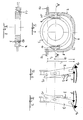
- FIGS. 1-4 Such a conventional transmission shifting device is shown in FIGS. 1-4 shown.
- a fixed sleeve 1 rotatably connected to a shaft 2.
- An axially displaceable sliding sleeve 3 is rotationally fixed on the fixed sleeve 1 arranged.
- the sliding sleeve 3 has one on its outer circumference circumferential groove 4, in which a shift fork 5 engages with a Shift rod 6 is connected.
- the shift rod 6 By actuating the shift rod 6, the Sliding sleeve 3 axially shifted and a gear can be switched.
- a shift rocker is U-shaped and points to both of them opposite legs swivel bearing on, in the gearbox Engage the bearing journal.
- FIGS. 5-8 A similar switching rocker 7 according to the prior art is shown in FIGS. 5-8.
- sliding blocks 10, 11 are movably mounted, which engage in the circumferential groove 4 of the sliding sleeve 3.
- the switching rocker 7 can be pivoted to the left or right about a pivot axis formed by bearing journals 12, 13, which is shown in FIGS. 6, 7.
- a driver 14 is provided for the pivoting actuation of the switching rocker 7, which driver is connected to a switching shaft, not shown here.
- a switching force introduced on the driver 14 by the selector shaft is increased at the point of its forwarding to the sliding sleeve 3, that is to say “at the level” of the line AA in the ratio r 1 / r 2 . Accordingly, a switching path "controlled" on the driver 14 by the switching shaft is reduced at the forwarding point to the sliding sleeve 3, that is to say approximately at the ratio AA 2 in the ratio r 2 / r 1 .
- a shift path s at the "introduction point" of the shift rocker 7 must be translated into a shift path s 'for forwarding to the shift sleeve at point P'.
- the switching force is increased approximately in the ratio r 1 / r 2 .
- the radius ratio r 2 / r 1 required for this would result in the pivot point P or the pivot axis of the shift rocker 7 being far below the gear set to be shifted and thus outside the transmission housing.
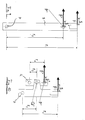
- an additional transmission lever is used in conventional transmissions, which is shown in FIG. 10.
- the transmission lever is pivoted about an axis P.
- the switching force F which is increased approximately in the ratio r 1 / r 2
- a force F ' is transmitted to the sliding sleeve, not shown here, which has been increased approximately in the ratio (r 1 / r 2 ) x (r 3 / r 4 ).
- the switching path s is reduced approximately in the ratio (r 2 / r 1 ) x (r 4 / r 3 ).
- the pivot point or the pivot axis Q of the shift rocker can thus be realized within the gearbox.
- a disadvantage of an additional transmission lever is the resulting additional play in the transmission path of the shifting force and a lower overall rigidity. This can lead to malfunctions during the switching process or impair the switching comfort.
- the object of the invention is one with respect to the above. Problems improved To create switching device.
- the basic principle of the invention consists in a gear shift device with a gearshift sleeve that is connected to a virtual swivel pole pivotable actuator is slidable.
- the actuator is stored in a sliding bearing device.
- the "sliding bearing device” can be formed for example by plain bearings. Alternatively, however, are other bearings are also suitable, e.g. Rolling bearings, in particular needle bearings. Moving the actuating element corresponds kinematically to one Swiveling movement around an only "virtual" swivel pole, the can lie outside the actuator.
- virtual pivot pole in this context means that the actuator in contrast to a conventional one Switch arm is not stored in the swivel pole. So the pivot pole is not gearbox related. It can even be outside the Gearbox are lying. With such an arrangement, any “Inner” translations between the force application point in the Actuator or the rocker arm and the “force diversion point” can be realized on the sliding sleeve.
- An actuating element according to the invention has at least two gearbox fixed "bearing points". Unlike one conventional shift rockers are the bearing points each by a “Pair” of “bearing elements” which are displaceable relative to one another are formed. Both both pairs of bearing elements are each one Bearing journal that can be moved in a guideway. The bearing journals can either slide in the assigned guideway be or roll on the guideway via roller bearings.
- the actuator is in the form of a "bracket" or a "U"
- the two "bearing points" are in a common level.
- the bearing points are preferably each formed by a journal which is closed in an associated Scenery guide is movable.
- the guideways or link guides can be made through recesses be formed, which are provided in the actuating element.
- the bearing journals are gear-fixed.
- the Guideways gear-fixed and the bearing pins on the actuating element arranged, i.e. be slidable together with the actuator.
- the slideways of the link guides can be smoothly curved Be curves. But it doesn't necessarily have to be separate Guideways may be provided. You don't have to either be closed.
- the guideways are exactly circular curved and have a common center of curvature.
- the actuating element has a "fixed" pivot pole on.
- the guideways can also be curved in a circle be without their centers of curvature coinciding. Then hangs the position of the swivel pole from the shift position of the Actuator, i.e. the swivel pole "moves" when moving of the actuator.
- the guideways are straight and parallel. In this case, the centers of curvature and the pivot pole of the Actuator in infinity.
- the guideways can several individual curved curve sections are formed, which are in themselves are “smooth”. Then in the transition areas of the curve sections There are “kinks”. Of course, the transition areas can also be rounded.
- FIG. 11 shows an actuating element 16 for axially displacing a shift sleeve (not shown) of a transmission.
- the actuating element 16 here has three "wings" 17-19.
- a driver 14 is provided, in which a shift finger 20 engages, which is firmly connected to a shift shaft 21.
- Transmission element 22 is provided, which over the switching shaft 21st switching force introduced into the actuating element 16 to a not here transmits shift sleeve shown and moves it axially.
- the link guides 22, 23 are curved in a circle, the average radius of curvature of the link guides 22, 23 being r 3 .
- the centers of curvature of the link guides 22, 23 coincide here at point P, which is a special case.
- the point P thus simultaneously corresponds to the instantaneous pivot pole (instantaneous pole) of the actuating element 16. Since the centers of curvature of the two link guides coincide, there is a further peculiarity, namely that the pivot pole P is fixed in position or gearbox regardless of the position of the actuating element 16.
- the sliding rocker or the actuating element 16 carries out a pivoting movement about the virtual pivot pole P, which is at a distance r 3 from the journal 24, 25. At point P ', which is at a distance r 2 from the pivoting pole P, the shifting force is passed on to the shift sleeve, not shown here.
- the guideways can also not be circularly curved.
- Another variant can they just be trained. When they're straight, but weird are arranged to each other, i.e. when their "extensions" cut, then the virtual pivot pole P shifts at one Displacement or when the actuating element 16 is pivoted.
- the actuating element 16 executes a purely translatory movement.
- the radii r 1 and r 2 are then infinite, that is, the virtual pivot pole P and the centers of curvature of the guideways are infinite.
- Figure 12 shows the actuator of Figure 11 in two different pivot positions. It can be seen that there must be some play between the driver 14 and the shift finger 20 so that the different inclined positions shown here can be assumed.
- the link guide 22 here consists of five guideway sections 26-30.
- the guideway sections 26-30 each have a circular course, the guideway sections 26, 28 and 30 each having a common center of curvature P 1 and the guideway sections 27, 29 being assigned a center of curvature P 2 .
- the centers of curvature P i "jump" during a switching operation.
- Each guideway section has its own radius of curvature.
- the shape of the guideways related to the gearbox housing or sliding rocker are determined by the position of the current virtual pivoting pole and the geometry of the bearing points.
- a transmission shifting device with an actuating element which has guideways as shown in FIG. 13, two gears can be shifted.
- the switching process is divided into three phases I-III.
- phases I and III the associated bearing journal of the actuating element executes a rotary movement around the pivot pole P 1 .
- phase II on the other hand, it performs a rotational movement around the pivot pole P 2 .
- the geometric conditions within a gearbox can Make actuation element necessary, in which a part of the gear housing or "sliding-arm-related" bearing tracks at any time of the switching process to the location of a first virtual pivot point Q relate, while another part of the gearbox or sliding arm-related Warehouses at any time of the circuit refer to the position of a second virtual pivot point Q '.
- Such an actuator is shown in Figure 14 .
- the link guides 22, 23 are circular here similar to Figure 11. In contrast to FIG. 11 , the link guides 22, 23, however, have different, that is to say non-coinciding, centers of curvature Q and Q ', to which the radii of curvature r 3 and r 3 ' are assigned.
- the instantaneous pivot pole P of the actuating element 16 or the sliding rocker is the intersection of the extended radii of curvature of the two link guides 22, 23.
Landscapes
- Engineering & Computer Science (AREA)
- General Engineering & Computer Science (AREA)
- Mechanical Engineering (AREA)
- Gear-Shifting Mechanisms (AREA)
Abstract
Description
- Figur 11
- ein Betätigungselement gemäß der Erfindung;
- Figur 12
- das Betätigungselement der Figur 11 in zwei verschiedenen Schaltstellungen;
- Figur 13
- eine Führungsbahn, die aus mehreren einzelnen Bahnabschnitten zusammengesetzt ist; und
- Figur 14
- eine weiteres Ausführungsbeispiel gemäß der Erfindung in drei verschiedenen Schaltstellung.
Claims (17)
- Getriebeschalteinrichtung mit
einem Betätigungselement zum axialen Verschieben einer Getriebeschaltmuffe, wobei das Betätigungselement um einen Schwenkpol schwenkbar ist und durch eine Lagereinrichtung im Getriebe gelagert ist, dadurch gekennzeichnet, dass die Lagereinrichtung eine Schiebelagereinrichtung (22 - 25) ist und dass der Schwenkpol (P) ein virtueller Schwenkpol ist. - Getriebeschalteinrichtung nach Anspruch 1, dadurch gekennzeichnet, dass der Schwenkpol (P) außerhalb des Betätigungselements (16) liegt.
- Getriebeschalteinrichtung nach Anspruch 1 oder 2, dadurch gekennzeichnet, dass die Schiebelagereinrichtung zwei voneinander beabstandete Lagerpunkte (24, 25) aufweist.
- Getriebeschalteinrichtung nach Anspruch 3, dadurch gekennzeichnet, dass jeder Lagerpunkt (24, 25) der Schiebelagereinrichtung durch eine Führungsbahn (22, 23) und einen relativ dazu verschieblichen Lagerzapfen (24, 25) gebildet ist.
- Getriebeschalteinrichtung nach Anspruch 4, dadurch gekennzeichnet, dass die Führungsbahnen (22, 23) durch mindestens eine im Betätigungselement (16) vorgesehene Ausnehmung gebildet sind dass und die Lagerzapfen (24, 25) getriebefest angeordnet sind.
- Getriebeschalteinrichtung nach Anspruch 4, dadurch gekennzeichnet, dass die Führungsbahnen (22, 23) getriebefest angeordnet sind und dass die Lagerzapfen (24, 25) fest mit dem Betätigungselement (16) verbunden sind.
- Getriebeschalteinrichtung nach einem der Ansprüche 4 bis 6, dadurch gekennzeichnet, dass die Führungsbahnen (22, 23) und der zugeordnete Lagerzapfen (24, 25) Gleitlager bilden.
- Getriebeschalteinrichtung nach einem der Ansprüche 4 bis 6, dadurch gekennzeichnet, dass zwischen den Lagerzapfen (24, 25) und den Führungsbahnen (22, 23) jeweils ein Wälzlager angeordnet ist.
- Getriebeschalteinrichtung nach einem der Ansprüche 1 bis 8, dadurch gekennzeichnet, dass die Führungsbahnen (22, 23) durch mindestens eine geschlossene Kulissenführung gebildet sind.
- Getriebeschalteinrichtung nach einem der Ansprüche 1 bis 9, dadurch gekennzeichnet, dass die Führungsbahnen durch zwei separate geschlossene Kulissenführungen (22, 23) gebildet sind.
- Getriebeschalteinrichtung nach einem der Ansprüche 4 bis 10, dadurch gekennzeichnet, dass die Führungsbahnen (22, 23) in einer gemeinsamen Ebene liegen.
- Getriebeschalteinrichtung nach einem der Ansprüche 4 bis 11, dadurch gekennzeichnet, dass die Führungsbahnen (22, 23) gekrümmte glatte Kurven sind.
- Getriebeschalteinrichtung nach einem der Ansprüche 4 bis 12, dadurch gekennzeichnet, dass die Führungsbahnen (22, 23) kreisförmig gekrümmt sind und einen gemeinsamen Krümmungsmittelpunkt (P) aufweisen.
- Getriebeschalteinrichtung nach einem der Ansprüche 4 bis 12, dadurch gekennzeichnet, dass die Führungsbahnen (22, 23) kreisförmig gekrümmt sind und jeweils einen separaten Krümmungsmittelpunkt (Q, Q') haben, die nicht zusammenfallen.
- Getriebeschalteinrichtung nach einem der Ansprüche 4 bis 11, dadurch gekennzeichnet, dass die Führungsbahnen (22, 23) gerade und parallel sind, wobei ihre Krümmungsmittelpunkte und der Schwenkpol des Betätigungselements (16) im Unendlichen liegen.
- Getriebeschalteinrichtung nach einem der Ansprüche 4 bis 14, dadurch gekennzeichnet, dass die Führungsbahnen (22, 23) jeweils gekrümmte glatte Kurvenabschnitte (26 - 30) aufweisen, wobei in den Übergangsbereichen der Kurvenabschnitte (26 - 30) gerundete Übergangsbereiche vorgesehen sind.
- Getriebeschalteinrichtung nach Anspruch 16, dadurch gekennzeichnet, dass mehreren Kurvenabschnitten (26 - 30) ein gemeinsamer Schwenkpol zugeordnet ist.
Applications Claiming Priority (2)
| Application Number | Priority Date | Filing Date | Title |
|---|---|---|---|
| DE10154089 | 2001-11-02 | ||
| DE10154089A DE10154089A1 (de) | 2001-11-02 | 2001-11-02 | Getriebeschalteinrichtung |
Publications (2)
| Publication Number | Publication Date |
|---|---|
| EP1308652A1 true EP1308652A1 (de) | 2003-05-07 |
| EP1308652B1 EP1308652B1 (de) | 2004-04-21 |
Family
ID=7704547
Family Applications (1)
| Application Number | Title | Priority Date | Filing Date |
|---|---|---|---|
| EP02022317A Expired - Lifetime EP1308652B1 (de) | 2001-11-02 | 2002-10-08 | Getriebeschalteinrichtung |
Country Status (2)
| Country | Link |
|---|---|
| EP (1) | EP1308652B1 (de) |
| DE (2) | DE10154089A1 (de) |
Cited By (1)
| Publication number | Priority date | Publication date | Assignee | Title |
|---|---|---|---|---|
| CN102149933B (zh) * | 2008-01-30 | 2014-10-29 | 谢夫勒科技股份两合公司 | 档位齿轮变速器的换档装置 |
Citations (3)
| Publication number | Priority date | Publication date | Assignee | Title |
|---|---|---|---|---|
| US2003794A (en) * | 1932-01-20 | 1935-06-04 | Gen Motors Corp | Gear shift mechanism |
| DE855365C (de) * | 1944-02-19 | 1952-11-13 | Patentverwertung W Reimers G M | Stufenlos durch Null regelbares Getriebe, insbesondere zum Lenken von Kettenfahrzeugen |
| DE19919271A1 (de) * | 1999-04-28 | 2000-11-02 | Schaeffler Waelzlager Ohg | Schaltschwinge für ein Zahnräderwechselgetriebe |
Family Cites Families (3)
| Publication number | Priority date | Publication date | Assignee | Title |
|---|---|---|---|---|
| DE3841780A1 (de) * | 1988-12-12 | 1990-08-23 | Porsche Ag | Betaetigungsvorrichtung fuer ein gangschaltgetriebe |
| DE4342957A1 (de) * | 1993-12-16 | 1995-06-22 | Zahnradfabrik Friedrichshafen | Schaltvorrichtung |
| DE19816385A1 (de) * | 1998-04-11 | 1999-10-14 | Zahnradfabrik Friedrichshafen | Schalteinrichtung für Zahnräder-Wechselgetriebe |
-
2001
- 2001-11-02 DE DE10154089A patent/DE10154089A1/de not_active Withdrawn
-
2002
- 2002-10-08 DE DE50200369T patent/DE50200369D1/de not_active Expired - Lifetime
- 2002-10-08 EP EP02022317A patent/EP1308652B1/de not_active Expired - Lifetime
Patent Citations (3)
| Publication number | Priority date | Publication date | Assignee | Title |
|---|---|---|---|---|
| US2003794A (en) * | 1932-01-20 | 1935-06-04 | Gen Motors Corp | Gear shift mechanism |
| DE855365C (de) * | 1944-02-19 | 1952-11-13 | Patentverwertung W Reimers G M | Stufenlos durch Null regelbares Getriebe, insbesondere zum Lenken von Kettenfahrzeugen |
| DE19919271A1 (de) * | 1999-04-28 | 2000-11-02 | Schaeffler Waelzlager Ohg | Schaltschwinge für ein Zahnräderwechselgetriebe |
Cited By (1)
| Publication number | Priority date | Publication date | Assignee | Title |
|---|---|---|---|---|
| CN102149933B (zh) * | 2008-01-30 | 2014-10-29 | 谢夫勒科技股份两合公司 | 档位齿轮变速器的换档装置 |
Also Published As
| Publication number | Publication date |
|---|---|
| DE10154089A1 (de) | 2003-05-15 |
| EP1308652B1 (de) | 2004-04-21 |
| DE50200369D1 (de) | 2004-05-27 |
Similar Documents
| Publication | Publication Date | Title |
|---|---|---|
| EP0731885B1 (de) | Schaltvorrichtung | |
| EP1412662B1 (de) | Schalteinrichtung für ein mehrstufiges schaltgetriebe | |
| EP0530466A1 (de) | Gangschaltung eines Kraftfahrzeuggetriebes | |
| EP3516271A2 (de) | Gang und gassen (xy)-getriebesteller | |
| DE19511510C1 (de) | Nockenscheiben-Anordnung einer Schaltkulisse für eine Schaltvorrichtung eines Zahnräderwechselgetriebes | |
| DE19520209B4 (de) | Schaltmechanismus für ein manuell schaltbares Getriebe | |
| DE102007035304A1 (de) | Schalteinrichtung für ein mehrgängiges Zahnräderwechselgetriebe eines Kraftfahrzeuges | |
| DE10151467A1 (de) | Schaltgetriebe mit Verriegelungseinrichtung zur Verriegelung einzelner Gänge | |
| EP1308652B1 (de) | Getriebeschalteinrichtung | |
| EP1825171B1 (de) | Schalteinrichtung eines handschaltgetriebes für kraftfahrzeuge | |
| DE4017957A1 (de) | Schalteinrichtung eines kraftfahrzeuggetriebe | |
| EP1531290A2 (de) | Schalteinrichtung | |
| WO2005078320A1 (de) | Einstangenschaltvorrichtung an einem schaltgetriebe | |
| DE10143885A1 (de) | Getriebeschaltvorrichtung | |
| DE10206470A1 (de) | Schaltgetriebe | |
| DE102018206392A1 (de) | Schalteinrichtung zur durchführung von gangwechseln in einem fahrzeuggetriebe | |
| DE60001023T2 (de) | Steuervorrichtung für den Gangwechsel eines mechanischen Getriebegehäuses eines Kraftfahrzeugs | |
| DE60006457T2 (de) | Getriebe kompakter Bauart mit Schwenkfüssen zur Betätigung von Schaltgabeln | |
| DE10146783B4 (de) | Lagerung eines Schalthebels | |
| EP1310707B1 (de) | Schaltvorrichtung für ein Wechselgetriebe und Verfahren zur Bewegung und Führung von Schaltgabeln in einem Wechselgetriebe | |
| DE102014206713A1 (de) | Übertragungseinrichtung von Wähl- und Schaltbewegungen und damit versehene Schalteinrichtung | |
| DE3008922A1 (de) | Schaltvorrichtung fuer das zahnradwechselgetriebe von kraftfahrzeugen | |
| EP0957296B1 (de) | Vorrichtung zum Anwählen und Schalten zwischen vorgegebenen Positionen | |
| DE4335992A1 (de) | Schaltvorrichtung für mehrgängiges Wechselgetriebe | |
| DE10252191A1 (de) | Schalteinrichtung eines Schaltgetriebes |
Legal Events
| Date | Code | Title | Description |
|---|---|---|---|
| PUAI | Public reference made under article 153(3) epc to a published international application that has entered the european phase |
Free format text: ORIGINAL CODE: 0009012 |
|
| 17P | Request for examination filed |
Effective date: 20030211 |
|
| AK | Designated contracting states |
Designated state(s): AT BE BG CH CY CZ DE DK EE ES FI FR GB GR IE IT LI LU MC NL PT SE SK TR |
|
| AX | Request for extension of the european patent |
Extension state: AL LT LV MK RO SI |
|
| GRAP | Despatch of communication of intention to grant a patent |
Free format text: ORIGINAL CODE: EPIDOSNIGR1 |
|
| AKX | Designation fees paid |
Designated state(s): DE FR GB IT |
|
| GRAS | Grant fee paid |
Free format text: ORIGINAL CODE: EPIDOSNIGR3 |
|
| GRAA | (expected) grant |
Free format text: ORIGINAL CODE: 0009210 |
|
| AK | Designated contracting states |
Kind code of ref document: B1 Designated state(s): DE FR GB IT |
|
| REG | Reference to a national code |
Ref country code: GB Ref legal event code: FG4D Free format text: NOT ENGLISH |
|
| GBT | Gb: translation of ep patent filed (gb section 77(6)(a)/1977) |
Effective date: 20040421 |
|
| REG | Reference to a national code |
Ref country code: IE Ref legal event code: FG4D Free format text: GERMAN |
|
| REF | Corresponds to: |
Ref document number: 50200369 Country of ref document: DE Date of ref document: 20040527 Kind code of ref document: P |
|
| REG | Reference to a national code |
Ref country code: IE Ref legal event code: FD4D |
|
| ET | Fr: translation filed | ||
| PLBE | No opposition filed within time limit |
Free format text: ORIGINAL CODE: 0009261 |
|
| STAA | Information on the status of an ep patent application or granted ep patent |
Free format text: STATUS: NO OPPOSITION FILED WITHIN TIME LIMIT |
|
| 26N | No opposition filed |
Effective date: 20050124 |
|
| PGFP | Annual fee paid to national office [announced via postgrant information from national office to epo] |
Ref country code: FR Payment date: 20141030 Year of fee payment: 13 Ref country code: GB Payment date: 20141030 Year of fee payment: 13 Ref country code: DE Payment date: 20141017 Year of fee payment: 13 |
|
| PGFP | Annual fee paid to national office [announced via postgrant information from national office to epo] |
Ref country code: IT Payment date: 20141027 Year of fee payment: 13 |
|
| REG | Reference to a national code |
Ref country code: DE Ref legal event code: R119 Ref document number: 50200369 Country of ref document: DE |
|
| GBPC | Gb: european patent ceased through non-payment of renewal fee |
Effective date: 20151008 |
|
| PG25 | Lapsed in a contracting state [announced via postgrant information from national office to epo] |
Ref country code: IT Free format text: LAPSE BECAUSE OF NON-PAYMENT OF DUE FEES Effective date: 20151008 Ref country code: DE Free format text: LAPSE BECAUSE OF NON-PAYMENT OF DUE FEES Effective date: 20160503 Ref country code: GB Free format text: LAPSE BECAUSE OF NON-PAYMENT OF DUE FEES Effective date: 20151008 |
|
| REG | Reference to a national code |
Ref country code: FR Ref legal event code: ST Effective date: 20160630 |
|
| PG25 | Lapsed in a contracting state [announced via postgrant information from national office to epo] |
Ref country code: FR Free format text: LAPSE BECAUSE OF NON-PAYMENT OF DUE FEES Effective date: 20151102 |