EP1308630A1 - Stator sector for a compressor of a turbomachine - Google Patents
Stator sector for a compressor of a turbomachine Download PDFInfo
- Publication number
- EP1308630A1 EP1308630A1 EP02292634A EP02292634A EP1308630A1 EP 1308630 A1 EP1308630 A1 EP 1308630A1 EP 02292634 A EP02292634 A EP 02292634A EP 02292634 A EP02292634 A EP 02292634A EP 1308630 A1 EP1308630 A1 EP 1308630A1
- Authority
- EP
- European Patent Office
- Prior art keywords
- housing
- rotation
- sectors
- fixed
- sectorized
- Prior art date
- Legal status (The legal status is an assumption and is not a legal conclusion. Google has not performed a legal analysis and makes no representation as to the accuracy of the status listed.)
- Granted
Links
Images

Classifications
-
- F—MECHANICAL ENGINEERING; LIGHTING; HEATING; WEAPONS; BLASTING
- F01—MACHINES OR ENGINES IN GENERAL; ENGINE PLANTS IN GENERAL; STEAM ENGINES
- F01D—NON-POSITIVE DISPLACEMENT MACHINES OR ENGINES, e.g. STEAM TURBINES
- F01D25/00—Component parts, details, or accessories, not provided for in, or of interest apart from, other groups
- F01D25/24—Casings; Casing parts, e.g. diaphragms, casing fastenings
- F01D25/246—Fastening of diaphragms or stator-rings
-
- F—MECHANICAL ENGINEERING; LIGHTING; HEATING; WEAPONS; BLASTING
- F01—MACHINES OR ENGINES IN GENERAL; ENGINE PLANTS IN GENERAL; STEAM ENGINES
- F01D—NON-POSITIVE DISPLACEMENT MACHINES OR ENGINES, e.g. STEAM TURBINES
- F01D9/00—Stators
- F01D9/02—Nozzles; Nozzle boxes; Stator blades; Guide conduits, e.g. individual nozzles
- F01D9/04—Nozzles; Nozzle boxes; Stator blades; Guide conduits, e.g. individual nozzles forming ring or sector
- F01D9/042—Nozzles; Nozzle boxes; Stator blades; Guide conduits, e.g. individual nozzles forming ring or sector fixing blades to stators
-
- F—MECHANICAL ENGINEERING; LIGHTING; HEATING; WEAPONS; BLASTING
- F04—POSITIVE - DISPLACEMENT MACHINES FOR LIQUIDS; PUMPS FOR LIQUIDS OR ELASTIC FLUIDS
- F04D—NON-POSITIVE-DISPLACEMENT PUMPS
- F04D29/00—Details, component parts, or accessories
- F04D29/40—Casings; Connections of working fluid
- F04D29/52—Casings; Connections of working fluid for axial pumps
- F04D29/54—Fluid-guiding means, e.g. diffusers
- F04D29/541—Specially adapted for elastic fluid pumps
- F04D29/542—Bladed diffusers
Definitions
- the invention presented here concerns the high pressure turbine of a turbomachine such as a turbojet engine used on an airplane. It concerns more precisely a sectorized fixed rectifier for a turbomachine compressor.
- US-A-4,126,405 discloses a segmented mounting of a turbine distributor.
- Document FR-A-2 728 015 discloses a stator distributor of a turbine comprising sectors each consisting of an inner segment and an outer segment connected by blades.
- a housing integrated in the stator of the compressor is intended to support the butted areas to each other. of the anti-rotation means are provided to prevent the rotation of the sectors supported by the housing.
- the present invention has been designed to to further improve the manufacture and cost of a fixed rectifier for turbomachine compressor.
- the housing is made in two parts or more, this which facilitates the manufacture.
- the parts of the housing and the rectifier sectors are associated by a system forming slide and slide.
- Anti-rotation means are designed to prevent the rotation of sectors relative to the crankcase.
- the housing is made of two parts in the shape of a semicircle.
- the casing comprising two radial flanks being face
- the slide means comprises two Opposite grooves made in flanks, edges external segments of the sectors constituting the slider means.
- the anti-rotation means fixed to the planes of joint can then include at least one bar immobilized between the two grooves by said means fastening and forming a stop for a sliding sector in a casing slide.
- This bar can be a pair of tweezers inserted by bringing the two branches together in dwellings of intended reception in the throats, and immobilized in these dwellings by loosening of the two branches, thus realizing said fixing means.
- Ways anti-rotation attached to the joint planes can also include at least one anti-rotation lock constituted by an element comprising slide means adapted to the slider means of the parts of the carter, the element also comprising means immobilization on the crankcase.
- These means immobilization can be of the tenon-mortise type, a tenon engaging in a mortise when the element is pushed in a direction perpendicular to the sliding direction of the element in the housing, thus realizing said fixing means.
- the segment outside the sector adjacent to that element may have one of its ends that has a clearance so that, when this adjacent sector is slipped on contact said element, the element can be pushed into said perpendicular direction.
- the anti-rotation means blocked on the parts of the housing may then comprise at least one anti-rotation lock constituted by an element comprising slide means adapted to means forming a slide of the parts of the casing, the element also comprising means immobilization on the crankcase.
- These means immobilization can be of the tenon-mortise type, a tenon engaging in a mortise when the element is pushed in a direction perpendicular to the sliding direction of the element in the housing, thereby realizing said locking means.
- the segment outside a sector adjacent to that element may have one of its ends that presents a clearance so that when this adjacent area is slipped into contact with said element, the element can be pushed in said perpendicular direction.
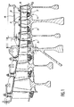
- Figure 1 is a partial sectional view of a compressor of a turbomachine using sectorized fixed rectifiers 1, 2 and 3 according to the invention. These rectifiers are functionally identical.
- the rectifier 1 will be described more precisely. It includes a built-in circular case 4 in the stator of the compressor and supporting sectors such as sector 5.
- a sector 5 consists of a segment inside 7 and an outer segment 6 connected between they by blades 8.
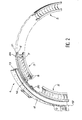
- Figure 2 is a partial view and exploded sectorized fixed rectifier 1. It includes example a housing in two parts in the form of a semicircle. Figure 2 shows partially one of the parts 11 of this case with one of his joint plans 12 intended to be fixed on a joint plane corresponding to the other part of the housing. Three sectors 5 being assembled are represented. For sector 5, we recognize the outer segment 6, the inner segment 7 and the blades 8 which connect them.
- the housing portion 11 comprises two flanks radial 12 and 13 facing each other and each provided of a throat.
- the throats are located vis-à-vis constitute a slide.
- the edges 21 and 22 of the segment outside 6 of sector 5 protrude outwards to ensure a slide function with respect to the slide formed by the casing portion 11.
- an anti-rotation lock is installed at the joint plane 12 of the housing part 11. It can be a bar or a lock such as the one shown in Figure 4.
- Figure 2 also shows an anti-rotation lock 30 disposed between two sectors 5.
- This latch 30 is shown in cavalier view in Figure 3. It is formed an element 31 which is placed between the two flanks 12 and 13 of the housing portion 11 (see Figure 2).
- the element 31 is in the shape of an arc of a circle and extended by an outer edge 32 and an inner edge 33.
- the edges 32 and 33 are provided so that the lock 30 can slide in the grooves of the part of casing 11.
- the outer edge 32 has a lug 34 protruding from the plane of the element 31. It is even for the lug 35 of the inner edge 33.
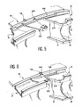
- Figures 5 and 6 illustrate two steps of setting up an anti-rotation lock 30 between two sectors. 5.
- a only flanks of the housing portion 11 has been represent. We can see the gorge 14 provided in this flank.
- Figure 5 shows a first sector 5 already installed (to the left of the figure) and a second Sector 5 being installed (on the right of the figure). Between these two sectors was introduced by sliding a latch 30. Note that the height of the groove 14 allows the passage of the outer edge of the latch 30 with his ergot 34.
- the element 30 is slipped to come into stop on the first sector 5. This corresponds to the element 30 at a position relative to the part of housing 11 such that the pin 34 is in vis-à-vis a notch 15 machined in the part of 11. Then just exercise on the lock 30 a push up (for the representation of Figures 5 and 6) for the pin 34 to enter the notch 15, the latch 30 being then in raised position.
- the second sector 5 can then be pushed to lock 30.
- This second sector 5 present, at the end in contact with the latch 30, a clearance 23 such as a portion of the outer segment 6 goes under lock 30.
- Anti-rotation bolt 40 of joint plane shown in Figure 4 is mounted in the same way than the lock in Figure 3. It is formed of an element 25 between the two sides of the casing. Element 41 is extended by an outer edge 42 and an inner edge 43. The outer edge 42 has a lug 44 projecting from the plane of element 41. The same applies to the lug 45 of the edge interior 43.
Abstract
Description
L'invention présentée ici concerne la turbine haute pression d'une turbomachine telle qu'un turboréacteur utilisé sur un avion. Elle concerne plus précisément un redresseur fixe sectorisé pour un compresseur de turbomachine.The invention presented here concerns the high pressure turbine of a turbomachine such as a turbojet engine used on an airplane. It concerns more precisely a sectorized fixed rectifier for a turbomachine compressor.
Il existe une très grande variété de compresseurs pour turbomachines. Les efforts des constructeurs portent sur l'amélioration des performances mais aussi sur l'amélioration de la fabrication, la réduction des coûts et la facilité de l'entretien.There is a very wide variety of compressors for turbomachines. The efforts of builders focus on improving performance but also on improving the manufacturing, cost reduction and ease of maintenance.
Une amélioration connue a consisté à sectoriser le redresseur fixe d'un compresseur pour turbomachine. Le brevet US-A-4 126 405 divulgue un montage segmenté d'un distributeur de turbine.A known improvement consisted of sectoriser the fixed rectifier of a compressor for turbine engine. US-A-4,126,405 discloses a segmented mounting of a turbine distributor.
Le document FR-A-2 728 015 divulgue un distributeur de stator d'une turbine comprenant des secteurs constitués chacun d'un segment intérieur et d'un segment extérieur reliés par des aubes. Un carter intégré dans le stator du compresseur est destiné à supporter les secteurs aboutés les uns aux autres. Des moyens anti-rotation sont prévus pour empêcher la rotation des secteurs supportés par le carter. Document FR-A-2 728 015 discloses a stator distributor of a turbine comprising sectors each consisting of an inner segment and an outer segment connected by blades. A housing integrated in the stator of the compressor is intended to support the butted areas to each other. of the anti-rotation means are provided to prevent the rotation of the sectors supported by the housing.
La présente invention a été conçue afin d'améliorer encore la fabrication et le coût d'un redresseur fixe pour compresseur de turbomachine. Pour cela le carter est réalisé en deux parties ou plus, ce qui facilite la fabrication. Les parties du carter et les secteurs de redresseur sont associés par un système formant glissière et coulisseau. Des moyens anti-rotation sont prévus pour éviter la rotation des secteurs par rapport au carter.The present invention has been designed to to further improve the manufacture and cost of a fixed rectifier for turbomachine compressor. For this the housing is made in two parts or more, this which facilitates the manufacture. The parts of the housing and the rectifier sectors are associated by a system forming slide and slide. Anti-rotation means are designed to prevent the rotation of sectors relative to the crankcase.
L'invention a donc pour objet un redresseur fixe sectorisé pour compresseur d'une turbomachine comprenant :
- des secteurs en forme d'arc de cercle constitués chacun d'un segment intérieur et d'un segment extérieur reliés par des aubes,
- un carter circulaire intégré dans le stator du compresseur et destiné à supporter les secteurs aboutés les uns aux autres,
- des moyens anti-rotation destinés à empêcher la rotation des secteurs supportés par le carter,
- le carter est constitué d'au moins deux parties, aboutées et fixées entre elles selon des plans de joint, comprenant des moyens formant glissière,
- les secteurs comprennent des moyens formant coulisseau adaptés aux moyens formant glissière des parties du carter,
- les moyens anti-rotation comprennent des moyens anti-rotation fixés aux plans de joint des parties du carter par des moyens de fixation, et des moyens anti-rotation bloqués sur les parties du carter par des moyens de blocage au niveau de l'aboutement des secteurs entre eux.
- arcuate sectors each consisting of an inner segment and an outer segment connected by vanes,
- a circular casing integrated in the stator of the compressor and intended to support the abutting sectors with each other,
- anti-rotation means for preventing the rotation of the sectors supported by the housing,
- the casing consists of at least two parts, abutting and fixed together in joint planes, comprising slide means,
- the sectors comprise slider means adapted to the slider means of the housing parts,
- the anti-rotation means comprise anti-rotation means fixed to the joint planes of the parts of the casing by fastening means, and anti-rotation means blocked on the parts of the casing by locking means at the abutment of the sectors between them.
De préférence, le carter est constitué de deux parties en forme de demi-cercle.Preferably, the housing is made of two parts in the shape of a semicircle.
Selon une variante de réalisation préférée, le carter comprenant deux flancs radiaux se faisant face, les moyens formant glissière comprennent deux gorges opposées réalisées dans les flancs, les bords des segments extérieurs des secteurs constituant les moyens formant coulisseau.According to a preferred embodiment variant, the casing comprising two radial flanks being face, the slide means comprises two Opposite grooves made in flanks, edges external segments of the sectors constituting the slider means.
Les moyens anti-rotation fixés aux plans de joint peuvent alors comprendre au moins une barrette immobilisée entre les deux rainures par lesdits moyens de fixation et formant butée pour un secteur coulissant dans une glissière du carter. Cette barrette peut être une pince à deux branches insérée par rapprochement des deux branches entre elles dans des logements de réception prévus dans les gorges, et immobilisée dans ces logements par relâchement des deux branches, réalisant ainsi lesdits moyens de fixation. Les moyens anti-rotation fixés aux plans de joint peuvent aussi comprendre au moins un verrou anti-rotation constitué par un élément comprenant des moyens formant coulisseau adaptés aux moyens formant glissière des parties du carter, l'élément comprenant également des moyens d'immobilisation sur le carter. Ces moyens d'immobilisation peuvent être du type tenon-mortaise, un tenon s'engageant dans une mortaise quand l'élément est poussé dans une direction perpendiculaire à la direction de glissement de l'élément dans le carter, réalisant ainsi lesdits moyens de fixation. Le segment extérieur du secteur adjacent audit élément peut avoir l'une de ses extrémités qui présente un dégagement afin que, lorsque ce secteur adjacent est glissé au contact dudit élément, l'élément puisse être poussé dans ladite direction perpendiculaire.The anti-rotation means fixed to the planes of joint can then include at least one bar immobilized between the two grooves by said means fastening and forming a stop for a sliding sector in a casing slide. This bar can be a pair of tweezers inserted by bringing the two branches together in dwellings of intended reception in the throats, and immobilized in these dwellings by loosening of the two branches, thus realizing said fixing means. Ways anti-rotation attached to the joint planes can also include at least one anti-rotation lock constituted by an element comprising slide means adapted to the slider means of the parts of the carter, the element also comprising means immobilization on the crankcase. These means immobilization can be of the tenon-mortise type, a tenon engaging in a mortise when the element is pushed in a direction perpendicular to the sliding direction of the element in the housing, thus realizing said fixing means. The segment outside the sector adjacent to that element may have one of its ends that has a clearance so that, when this adjacent sector is slipped on contact said element, the element can be pushed into said perpendicular direction.
Les moyens anti-rotation bloqués sur les parties du carter peuvent alors comprendre au moins un verrou anti-rotation constitué par un élément comprenant des moyens formant coulisseau adaptés aux moyens formant glissière des parties du carter, l'élément comprenant également des moyens d'immobilisation sur le carter. Ces moyens d'immobilisation peuvent être du type tenon-mortaise, un tenon s'engageant dans une mortaise quand l'élément est poussé dans une direction perpendiculaire à la direction de glissement de l'élément dans le carter, réalisant ainsi lesdits moyens de blocage. Le segment extérieur d'un secteur adjacent audit élément peut avoir l'une de ses extrémités qui présente un dégagement afin que, lorsque ce secteur adjacent est glissé au contact dudit élément, l'élément puisse être poussé dans ladite direction perpendiculaire.The anti-rotation means blocked on the parts of the housing may then comprise at least one anti-rotation lock constituted by an element comprising slide means adapted to means forming a slide of the parts of the casing, the element also comprising means immobilization on the crankcase. These means immobilization can be of the tenon-mortise type, a tenon engaging in a mortise when the element is pushed in a direction perpendicular to the sliding direction of the element in the housing, thereby realizing said locking means. The segment outside a sector adjacent to that element may have one of its ends that presents a clearance so that when this adjacent area is slipped into contact with said element, the element can be pushed in said perpendicular direction.
L'invention sera mieux comprise et d'autres avantages et particularités apparaítront à la lecture de la description qui va suivre, donnée à titre d'exemple non limitatif, accompagnée des dessins annexés parmi lesquels :
- la figure 1 est une vue partielle en coupe d'un compresseur d'un turbomachine utilisant un redresseur fixe sectorisé selon l'invention,
- la figure 2 est une vue partielle et éclatée d'un redresseur fixe sectorisé selon l'invention,
- la figure 3 est une vue cavalière d'un verrou anti-rotation pour plan de joint d'une partie de carter pour le redresseur fixe sectorisé de l'invention,
- la figure 4 est une vue cavalière d'un verrou anti-rotation disposé entre deux secteurs d'un redresseur fixe sectorisé selon l'invention,
- les figures 5 et 6 illustrent deux étapes de la mise en place d'un verrou anti-rotation entre deux secteurs d'un redresseur fixe sectorisé selon l'invention.
- FIG. 1 is a partial sectional view of a compressor of a turbomachine using a sectored fixed rectifier according to the invention,
- FIG. 2 is a fragmentary and exploded view of a sectored fixed rectifier according to the invention,
- FIG. 3 is a side view of an anti-rotation latch for a joint plane of a housing part for the sectorized fixed rectifier of the invention,
- FIG. 4 is a side view of an anti-rotation lock disposed between two sectors of a sectored fixed rectifier according to the invention,
- Figures 5 and 6 illustrate two steps of the establishment of an anti-rotation lock between two sectors of a sectored fixed rectifier according to the invention.
La figure 1 est une vue partielle en coupe
d'un compresseur d'une turbomachine utilisant des
redresseurs fixes sectorisés 1, 2 et 3 selon
l'invention. Ces redresseurs sont fonctionnellement
identiques.Figure 1 is a partial sectional view
of a compressor of a turbomachine using
sectorized
Le redresseur 1 va être décrit plus
précisément. Il comprend un carter circulaire 4 intégré
dans le stator du compresseur et supportant des
secteurs tel que le secteur 5. The rectifier 1 will be described more
precisely. It includes a built-in circular case 4
in the stator of the compressor and supporting
sectors such as
Un secteur 5 est constitué d'un segment
intérieur 7 et d'un segment extérieur 6 reliés entre
eux par des aubes 8.A
La figure 2 est une vue partielle et
éclatée du redresseur fixe sectorisé 1. Il comprend par
exemple un carter en deux parties en forme de demi-cercle.
La figure 2 montre partiellement l'une des
parties 11 de ce carter avec l'un de ses plans de joint
12 destiné à être fixé sur un plan de joint
correspondant de l'autre partie du carter. Trois
secteurs 5 en cours de montage sont représentés. Pour
un secteur 5, on reconnaít le segment extérieur 6, le
segment intérieur 7 et les aubes 8 qui les relient.Figure 2 is a partial view and
exploded sectorized fixed rectifier 1. It includes
example a housing in two parts in the form of a semicircle.
Figure 2 shows partially one of the
La partie de carter 11 comprend deux flancs
radiaux 12 et 13 se faisant face et pourvus chacun
d'une gorge. Les gorges sont situées en vis-à-vis pour
constituer une glissière. Les bords 21 et 22 du segment
extérieur 6 du secteur 5 font saillie vers l'extérieur
pour assurer une fonction de coulisseau par rapport à
la glissière formée par la partie de carter 11.The
Avant d'engager un premier secteur 5 sur la
partie de carter 11, un verrou anti-rotation est
installé au plan de joint 12 de la partie de carter 11.
Il peut s'agir d'une barrette ou d'un verrou tel que
celui représenté à la figure 4.Before engaging a
La figure 2 montre aussi un verrou anti-rotation
30 disposé entre deux secteurs 5. Ce verrou 30
est montré en vue cavalière à la figure 3. Il est formé
d'un élément 31 qui se place entre les deux flancs 12
et 13 de la partie de carter 11 (voir la figure 2).
L'élément 31 est en forme d'arc de cercle et se
prolonge par un bord extérieur 32 et un bord intérieur
33. Les bords 32 et 33 sont prévus pour que le verrou
30 puisse coulisser dans les gorges de la partie de
carter 11. Le bord extérieur 32 comporte un ergot 34
faisant saillie du plan de l'élément 31. Il en va de
même pour l'ergot 35 du bord intérieur 33.Figure 2 also shows an
Les figures 5 et 6 illustrent deux étapes
de la mise en place d'un verrou anti-rotation 30 entre
deux secteurs 5. Pour une meilleure compréhension, un
seul des flancs de la partie de carter 11 a été
représenté. On aperçoit la gorge 14 prévue dans ce
flanc.Figures 5 and 6 illustrate two steps
of setting up an
La figure 5 montre un premier secteur 5
déjà installé (à gauche de la figure) et un deuxième
secteur 5 en cours de montage (à droite de la figure).
Entre ces deux secteurs a été introduit par glissement
un verrou 30. On remarque que la hauteur de la gorge 14
permet le passage du bord extérieur du verrou 30 avec
son ergot 34.Figure 5 shows a
L'élément 30 est glissé jusqu'à venir en
butée sur le premier secteur 5. Ceci correspond pour
l'élément 30 à une position relative par rapport à la
partie de carter 11 telle que l'ergot 34 se trouve en
vis-à-vis d'une encoche 15 usinée dans la partie de
carter 11. Il suffit alors d'exercer sur le verrou 30
une poussée vers le haut (pour la représentation des
figures 5 et 6) pour que l'ergot 34 pénètre dans
l'encoche 15, le verrou 30 se trouvant alors en
position surélevée.The
Le deuxième secteur 5 peut alors être
poussé vers le verrou 30. Ce deuxième secteur 5
présente, à l'extrémité en contact avec le verrou 30,
un dégagement 23 tel qu'une partie du segment extérieur
6 passe sous le verrou 30.The
Le verrou anti-rotation 40 de plan de joint
représenté à la figure 4 se monte de la même manière
que le verrou de la figure 3. Il est formé d'un élément
41 qui se place entre les deux flancs de la partie de
carter. L'élément 41 se prolonge par un bord extérieur
42 et un bord intérieur 43. Le bord extérieur 42
comporte un ergot 44 faisant saillie du plan de
l'élément 41. Il en va de même pour l'ergot 45 du bord
intérieur 43.
Claims (11)
Applications Claiming Priority (2)
| Application Number | Priority Date | Filing Date | Title |
|---|---|---|---|
| FR0114102A FR2831615B1 (en) | 2001-10-31 | 2001-10-31 | SECTORIZED FIXED RECTIFIER FOR A TURBOMACHINE COMPRESSOR |
| FR0114102 | 2001-10-31 |
Publications (2)
| Publication Number | Publication Date |
|---|---|
| EP1308630A1 true EP1308630A1 (en) | 2003-05-07 |
| EP1308630B1 EP1308630B1 (en) | 2006-08-23 |
Family
ID=8868935
Family Applications (1)
| Application Number | Title | Priority Date | Filing Date |
|---|---|---|---|
| EP02292634A Expired - Lifetime EP1308630B1 (en) | 2001-10-31 | 2002-10-24 | Stator sector for a compressor of a turbomachine |
Country Status (9)
| Country | Link |
|---|---|
| US (1) | US6890151B2 (en) |
| EP (1) | EP1308630B1 (en) |
| JP (1) | JP4181375B2 (en) |
| CA (1) | CA2409972C (en) |
| DE (1) | DE60214106T2 (en) |
| ES (1) | ES2266430T3 (en) |
| FR (1) | FR2831615B1 (en) |
| RU (1) | RU2287090C2 (en) |
| UA (1) | UA75069C2 (en) |
Cited By (5)
| Publication number | Priority date | Publication date | Assignee | Title |
|---|---|---|---|---|
| FR2859509A1 (en) * | 2003-09-10 | 2005-03-11 | Snecma Moteurs | Rectifier vanes rotation stopping device for turbo-machine, has bar with pair of ends inserted in groove of housing, where each end has axial surface contacting axial surface of respective housing |
| FR2948736A1 (en) * | 2009-07-31 | 2011-02-04 | Snecma | EXTERNAL VIROLE SECTOR FOR AIRBORNE TURBOMACHINE AIRBORNE STATOR CROWN, COMPRISING SHOCK ABSORBING MOUNTS |
| WO2012153037A1 (en) * | 2011-05-09 | 2012-11-15 | Snecma | Aircraft engine annular shroud comprising an opening for the insertion of blades |
| EP2933437A1 (en) * | 2014-04-16 | 2015-10-21 | United Technologies Corporation | Systems and methods for anti-rotation features |
| EP2943658B1 (en) | 2013-01-08 | 2017-03-29 | United Technologies Corporation | Stator anti-rotation device |
Families Citing this family (19)
| Publication number | Priority date | Publication date | Assignee | Title |
|---|---|---|---|---|
| US7033135B2 (en) | 2003-11-10 | 2006-04-25 | General Electric Company | Method and apparatus for distributing fluid into a turbomachine |
| US7144218B2 (en) * | 2004-04-19 | 2006-12-05 | United Technologies Corporation | Anti-rotation lock |
| FR2878293B1 (en) * | 2004-11-24 | 2009-08-21 | Snecma Moteurs Sa | MOUNTING DISTRIBUTOR SECTIONS IN AXIAL COMPRESSOR |
| JP4918263B2 (en) * | 2006-01-27 | 2012-04-18 | 三菱重工業株式会社 | Stator blade ring of axial compressor |
| US20080025838A1 (en) * | 2006-07-25 | 2008-01-31 | Siemens Power Generation, Inc. | Ring seal for a turbine engine |
| US8128354B2 (en) * | 2007-01-17 | 2012-03-06 | Siemens Energy, Inc. | Gas turbine engine |
| FR2913052B1 (en) * | 2007-02-22 | 2011-04-01 | Snecma | CONTROL OF AUBES WITH VARIABLE SETTING ANGLE |
| EP2211023A1 (en) * | 2009-01-21 | 2010-07-28 | Siemens Aktiengesellschaft | Guide vane system for a turbomachine with segmented guide vane carrier |
| GB2468848B (en) * | 2009-03-23 | 2011-10-26 | Rolls Royce Plc | An assembly for a turbomachine |
| EP2339120B1 (en) * | 2009-12-22 | 2015-07-08 | Techspace Aero S.A. | Turbomachine stator stage and corresponding compressor |
| US8454303B2 (en) * | 2010-01-14 | 2013-06-04 | General Electric Company | Turbine nozzle assembly |
| US20110243725A1 (en) * | 2010-03-31 | 2011-10-06 | General Electric Company | Turbine shroud mounting apparatus with anti-rotation feature |
| US9074489B2 (en) | 2012-03-26 | 2015-07-07 | Pratt & Whitney Canada Corp. | Connector assembly for variable inlet guide vanes and method |
| US10428832B2 (en) | 2012-08-06 | 2019-10-01 | United Technologies Corporation | Stator anti-rotation lug |
| US10309235B2 (en) | 2012-08-27 | 2019-06-04 | United Technologies Corporation | Shiplap cantilevered stator |
| US10190434B2 (en) * | 2014-10-29 | 2019-01-29 | Rolls-Royce North American Technologies Inc. | Turbine shroud with locating inserts |
| US11008893B2 (en) * | 2014-11-03 | 2021-05-18 | Nuovo Pignone Srl | Sector for the assembly of a stage of a turbine and corresponding manufacturing method |
| BE1023619B1 (en) * | 2015-06-26 | 2017-05-18 | Safran Aero Boosters S.A. | COMPRESSOR HOUSING OF AXIAL TURBOMACHINE |
| US20190309641A1 (en) * | 2018-04-04 | 2019-10-10 | United Technologies Corporation | Gas turbine engine having cantilevered stators with sealing members |
Citations (4)
| Publication number | Priority date | Publication date | Assignee | Title |
|---|---|---|---|---|
| US2945290A (en) * | 1957-09-16 | 1960-07-19 | Gen Electric | Stator vane half ring assemblies |
| US4126405A (en) * | 1976-12-16 | 1978-11-21 | General Electric Company | Turbine nozzle |
| FR2728015A1 (en) * | 1994-12-07 | 1996-06-14 | Snecma | SECTORIZED MONOBLOC DISPENSER OF TURBOMACHINE TURBINE STATOR |
| EP1104836A2 (en) * | 1999-12-03 | 2001-06-06 | General Electric Company | Vane sector seating spring and method of retaining same |
Family Cites Families (6)
| Publication number | Priority date | Publication date | Assignee | Title |
|---|---|---|---|---|
| US3365173A (en) * | 1966-02-28 | 1968-01-23 | Gen Electric | Stator structure |
| US4126914A (en) | 1976-06-22 | 1978-11-28 | Cotton, Incorporated | Process and apparatus for treating fibrous materials for subsequent processing |
| US4889470A (en) * | 1988-08-01 | 1989-12-26 | Westinghouse Electric Corp. | Compressor diaphragm assembly |
| US5197856A (en) * | 1991-06-24 | 1993-03-30 | General Electric Company | Compressor stator |
| US5141395A (en) * | 1991-09-05 | 1992-08-25 | General Electric Company | Flow activated flowpath liner seal |
| US5846050A (en) * | 1997-07-14 | 1998-12-08 | General Electric Company | Vane sector spring |
-
2001
- 2001-10-31 FR FR0114102A patent/FR2831615B1/en not_active Expired - Fee Related
-
2002
- 2002-10-24 EP EP02292634A patent/EP1308630B1/en not_active Expired - Lifetime
- 2002-10-24 DE DE60214106T patent/DE60214106T2/en not_active Expired - Lifetime
- 2002-10-24 JP JP2002309259A patent/JP4181375B2/en not_active Expired - Lifetime
- 2002-10-24 ES ES02292634T patent/ES2266430T3/en not_active Expired - Lifetime
- 2002-10-28 CA CA2409972A patent/CA2409972C/en not_active Expired - Lifetime
- 2002-10-30 US US10/283,279 patent/US6890151B2/en not_active Expired - Lifetime
- 2002-10-30 UA UA2002108634A patent/UA75069C2/en unknown
- 2002-10-30 RU RU2002129117/06A patent/RU2287090C2/en active
Patent Citations (4)
| Publication number | Priority date | Publication date | Assignee | Title |
|---|---|---|---|---|
| US2945290A (en) * | 1957-09-16 | 1960-07-19 | Gen Electric | Stator vane half ring assemblies |
| US4126405A (en) * | 1976-12-16 | 1978-11-21 | General Electric Company | Turbine nozzle |
| FR2728015A1 (en) * | 1994-12-07 | 1996-06-14 | Snecma | SECTORIZED MONOBLOC DISPENSER OF TURBOMACHINE TURBINE STATOR |
| EP1104836A2 (en) * | 1999-12-03 | 2001-06-06 | General Electric Company | Vane sector seating spring and method of retaining same |
Cited By (13)
| Publication number | Priority date | Publication date | Assignee | Title |
|---|---|---|---|---|
| FR2859509A1 (en) * | 2003-09-10 | 2005-03-11 | Snecma Moteurs | Rectifier vanes rotation stopping device for turbo-machine, has bar with pair of ends inserted in groove of housing, where each end has axial surface contacting axial surface of respective housing |
| EP1515002A1 (en) * | 2003-09-10 | 2005-03-16 | Snecma Moteurs | Anti-rotation means for turbine stator vanes in the split plane of the casing |
| US7059832B2 (en) | 2003-09-10 | 2006-06-13 | Snecma Moteurs | Rotation-locking of sectors of rectifier blades by bars in the parting planes of the housing |
| FR2948736A1 (en) * | 2009-07-31 | 2011-02-04 | Snecma | EXTERNAL VIROLE SECTOR FOR AIRBORNE TURBOMACHINE AIRBORNE STATOR CROWN, COMPRISING SHOCK ABSORBING MOUNTS |
| WO2011012679A3 (en) * | 2009-07-31 | 2011-04-21 | Snecma | Outer shell sector for a bladed stator ring of an aircraft turbine engine, comprising vibration-damping blocks |
| FR2975124A1 (en) * | 2011-05-09 | 2012-11-16 | Snecma | AIRCRAFT ENGINE ANNULAR VIRO COMPRISING AN AUBES INTRODUCTION WINDOW |
| WO2012153037A1 (en) * | 2011-05-09 | 2012-11-15 | Snecma | Aircraft engine annular shroud comprising an opening for the insertion of blades |
| GB2504883A (en) * | 2011-05-09 | 2014-02-12 | Snecma | Aircraft engine annular shroud comprising an opening for the insertion of blades |
| GB2504883B (en) * | 2011-05-09 | 2017-12-13 | Snecma | Aircraft engine annular shroud comprising an opening for the insertion of blades |
| US9879549B2 (en) | 2011-05-09 | 2018-01-30 | Snecma | Aircraft engine annular shroud comprising an opening for the insertion of blades |
| EP2943658B1 (en) | 2013-01-08 | 2017-03-29 | United Technologies Corporation | Stator anti-rotation device |
| EP2933437A1 (en) * | 2014-04-16 | 2015-10-21 | United Technologies Corporation | Systems and methods for anti-rotation features |
| US9745864B2 (en) | 2014-04-16 | 2017-08-29 | United Technologies Corporation | Systems and methods for anti-rotational features |
Also Published As
| Publication number | Publication date |
|---|---|
| JP4181375B2 (en) | 2008-11-12 |
| US20030082051A1 (en) | 2003-05-01 |
| DE60214106T2 (en) | 2007-04-12 |
| US6890151B2 (en) | 2005-05-10 |
| EP1308630B1 (en) | 2006-08-23 |
| FR2831615B1 (en) | 2004-01-02 |
| CA2409972A1 (en) | 2003-04-30 |
| RU2287090C2 (en) | 2006-11-10 |
| CA2409972C (en) | 2011-04-12 |
| UA75069C2 (en) | 2006-03-15 |
| DE60214106D1 (en) | 2006-10-05 |
| FR2831615A1 (en) | 2003-05-02 |
| ES2266430T3 (en) | 2007-03-01 |
| JP2003161297A (en) | 2003-06-06 |
Similar Documents
| Publication | Publication Date | Title |
|---|---|---|
| EP1308630B1 (en) | Stator sector for a compressor of a turbomachine | |
| EP1970537B1 (en) | Turbomachine fan | |
| EP1439282B1 (en) | Device for mounting an annular flask at a radial side of a rotor | |
| EP2060750B1 (en) | Stage of a turbine or compressor, in particular of a turbomachine | |
| CA2639206C (en) | Stage of variable pitch vanes for a turbomachine | |
| CA2554092C (en) | Fan rotor blade locking system | |
| EP2053203B1 (en) | Improvement of a ring for controlling the pitch of stator vanes of a turbomachine. | |
| CA2802821C (en) | Angular stator sector for a turbomachine compressor, turbomachine stator and turbomachine comprising such a sector | |
| FR2887920A1 (en) | Fixing for ring sectors on turbine housing has at least some component edges made with surfaces shaped to prevent axial movement of locking elements | |
| FR3014151A1 (en) | BLOWER, ESPECIALLY FOR A TURBOMACHINE | |
| WO2015079163A1 (en) | Fan for a turbomachine | |
| EP1524406B1 (en) | Configuration of a turbomachine rotor blade | |
| WO2015079156A1 (en) | Device for centring and guiding the rotation of a turbine engine shaft including improved means for retaining the external bearing ring | |
| EP0953729B1 (en) | Guide vanes for a turbomachine | |
| FR2971022A1 (en) | COMPRESSOR RECTIFIER STAGE FOR A TURBOMACHINE | |
| EP1662093B1 (en) | Zusammenbau von Leitsegmente in einem axialen Kompressor | |
| FR2729709A1 (en) | Turbine rotor seal and retainer | |
| CA2644312C (en) | Turbine engine turbine or compressor stage | |
| FR2873745A1 (en) | ROTOR DISC OF TURBOMACHINE | |
| FR2756021A1 (en) | Automobile engine fan with simplified blade mounting | |
| FR2779681A1 (en) | Assembly of combined inlet distributor and manifold | |
| FR3106632A1 (en) | STATOR BLADE FOR AN AIRCRAFT TURBOMACHINE | |
| FR2983247A1 (en) | Rectifier-intermediate casing assembly for turboshaft engine e.g. turbojet, has blocking unit blocking rotation of internal ring with respect to casing, where unit is attached with internal ring by abutment in circumferential direction | |
| FR3085994A1 (en) | AXIAL RETENTION RING OF BLADES FOR MOBILE WHEEL OF TURBOMACHINE, PREFERABLY FOR AIRCRAFT |
Legal Events
| Date | Code | Title | Description |
|---|---|---|---|
| PUAI | Public reference made under article 153(3) epc to a published international application that has entered the european phase |
Free format text: ORIGINAL CODE: 0009012 |
|
| 17P | Request for examination filed |
Effective date: 20021108 |
|
| AK | Designated contracting states |
Designated state(s): AT BE BG CH CY CZ DE DK EE ES FI FR GB GR IE IT LI LU MC NL PT SE SK TR |
|
| AX | Request for extension of the european patent |
Extension state: AL LT LV MK RO SI |
|
| AKX | Designation fees paid |
Designated state(s): DE ES FR GB IT SE |
|
| RAP1 | Party data changed (applicant data changed or rights of an application transferred) |
Owner name: SNECMA |
|
| GRAP | Despatch of communication of intention to grant a patent |
Free format text: ORIGINAL CODE: EPIDOSNIGR1 |
|
| GRAS | Grant fee paid |
Free format text: ORIGINAL CODE: EPIDOSNIGR3 |
|
| GRAA | (expected) grant |
Free format text: ORIGINAL CODE: 0009210 |
|
| AK | Designated contracting states |
Kind code of ref document: B1 Designated state(s): DE ES FR GB IT SE |
|
| PG25 | Lapsed in a contracting state [announced via postgrant information from national office to epo] |
Ref country code: IT Free format text: LAPSE BECAUSE OF FAILURE TO SUBMIT A TRANSLATION OF THE DESCRIPTION OR TO PAY THE FEE WITHIN THE PRESCRIBED TIME-LIMIT;WARNING: LAPSES OF ITALIAN PATENTS WITH EFFECTIVE DATE BEFORE 2007 MAY HAVE OCCURRED AT ANY TIME BEFORE 2007. THE CORRECT EFFECTIVE DATE MAY BE DIFFERENT FROM THE ONE RECORDED. Effective date: 20060823 |
|
| REG | Reference to a national code |
Ref country code: GB Ref legal event code: FG4D Free format text: NOT ENGLISH |
|
| REF | Corresponds to: |
Ref document number: 60214106 Country of ref document: DE Date of ref document: 20061005 Kind code of ref document: P |
|
| GBT | Gb: translation of ep patent filed (gb section 77(6)(a)/1977) |
Effective date: 20060928 |
|
| REG | Reference to a national code |
Ref country code: SE Ref legal event code: TRGR |
|
| REG | Reference to a national code |
Ref country code: ES Ref legal event code: FG2A Ref document number: 2266430 Country of ref document: ES Kind code of ref document: T3 |
|
| PLBE | No opposition filed within time limit |
Free format text: ORIGINAL CODE: 0009261 |
|
| STAA | Information on the status of an ep patent application or granted ep patent |
Free format text: STATUS: NO OPPOSITION FILED WITHIN TIME LIMIT |
|
| 26N | No opposition filed |
Effective date: 20070524 |
|
| PGFP | Annual fee paid to national office [announced via postgrant information from national office to epo] |
Ref country code: ES Payment date: 20121005 Year of fee payment: 11 |
|
| REG | Reference to a national code |
Ref country code: ES Ref legal event code: FD2A Effective date: 20150710 |
|
| PG25 | Lapsed in a contracting state [announced via postgrant information from national office to epo] |
Ref country code: ES Free format text: LAPSE BECAUSE OF NON-PAYMENT OF DUE FEES Effective date: 20131025 |
|
| REG | Reference to a national code |
Ref country code: FR Ref legal event code: PLFP Year of fee payment: 14 |
|
| REG | Reference to a national code |
Ref country code: FR Ref legal event code: PLFP Year of fee payment: 15 |
|
| REG | Reference to a national code |
Ref country code: FR Ref legal event code: PLFP Year of fee payment: 16 |
|
| REG | Reference to a national code |
Ref country code: FR Ref legal event code: CD Owner name: SAFRAN AIRCRAFT ENGINES Effective date: 20170719 |
|
| REG | Reference to a national code |
Ref country code: FR Ref legal event code: PLFP Year of fee payment: 17 |
|
| PGFP | Annual fee paid to national office [announced via postgrant information from national office to epo] |
Ref country code: FR Payment date: 20210922 Year of fee payment: 20 Ref country code: IT Payment date: 20210922 Year of fee payment: 20 |
|
| PGFP | Annual fee paid to national office [announced via postgrant information from national office to epo] |
Ref country code: GB Payment date: 20210922 Year of fee payment: 20 Ref country code: SE Payment date: 20210921 Year of fee payment: 20 |
|
| PGFP | Annual fee paid to national office [announced via postgrant information from national office to epo] |
Ref country code: DE Payment date: 20210921 Year of fee payment: 20 |
|
| REG | Reference to a national code |
Ref country code: DE Ref legal event code: R071 Ref document number: 60214106 Country of ref document: DE |
|
| REG | Reference to a national code |
Ref country code: GB Ref legal event code: PE20 Expiry date: 20221023 |
|
| REG | Reference to a national code |
Ref country code: SE Ref legal event code: EUG |
|
| PG25 | Lapsed in a contracting state [announced via postgrant information from national office to epo] |
Ref country code: GB Free format text: LAPSE BECAUSE OF EXPIRATION OF PROTECTION Effective date: 20221023 |