EP1308362A1 - Indicateur d'etat de frein de stationnement - Google Patents
Indicateur d'etat de frein de stationnement Download PDFInfo
- Publication number
- EP1308362A1 EP1308362A1 EP02257293A EP02257293A EP1308362A1 EP 1308362 A1 EP1308362 A1 EP 1308362A1 EP 02257293 A EP02257293 A EP 02257293A EP 02257293 A EP02257293 A EP 02257293A EP 1308362 A1 EP1308362 A1 EP 1308362A1
- Authority
- EP
- European Patent Office
- Prior art keywords
- warning
- handbrake
- condition
- vehicle
- switch
- Prior art date
- Legal status (The legal status is an assumption and is not a legal conclusion. Google has not performed a legal analysis and makes no representation as to the accuracy of the status listed.)
- Withdrawn
Links
Images


Classifications
-
- B—PERFORMING OPERATIONS; TRANSPORTING
- B60—VEHICLES IN GENERAL
- B60T—VEHICLE BRAKE CONTROL SYSTEMS OR PARTS THEREOF; BRAKE CONTROL SYSTEMS OR PARTS THEREOF, IN GENERAL; ARRANGEMENT OF BRAKING ELEMENTS ON VEHICLES IN GENERAL; PORTABLE DEVICES FOR PREVENTING UNWANTED MOVEMENT OF VEHICLES; VEHICLE MODIFICATIONS TO FACILITATE COOLING OF BRAKES
- B60T17/00—Component parts, details, or accessories of power brake systems not covered by groups B60T8/00, B60T13/00 or B60T15/00, or presenting other characteristic features
- B60T17/18—Safety devices; Monitoring
- B60T17/22—Devices for monitoring or checking brake systems; Signal devices
- B60T17/221—Procedure or apparatus for checking or keeping in a correct functioning condition of brake systems
-
- B—PERFORMING OPERATIONS; TRANSPORTING
- B60—VEHICLES IN GENERAL
- B60Q—ARRANGEMENT OF SIGNALLING OR LIGHTING DEVICES, THE MOUNTING OR SUPPORTING THEREOF OR CIRCUITS THEREFOR, FOR VEHICLES IN GENERAL
- B60Q1/00—Arrangement of optical signalling or lighting devices, the mounting or supporting thereof or circuits therefor
- B60Q1/26—Arrangement of optical signalling or lighting devices, the mounting or supporting thereof or circuits therefor the devices being primarily intended to indicate the vehicle, or parts thereof, or to give signals, to other traffic
- B60Q1/44—Arrangement of optical signalling or lighting devices, the mounting or supporting thereof or circuits therefor the devices being primarily intended to indicate the vehicle, or parts thereof, or to give signals, to other traffic for indicating braking action or preparation for braking, e.g. by detection of the foot approaching the brake pedal
-
- G—PHYSICS
- G07—CHECKING-DEVICES
- G07C—TIME OR ATTENDANCE REGISTERS; REGISTERING OR INDICATING THE WORKING OF MACHINES; GENERATING RANDOM NUMBERS; VOTING OR LOTTERY APPARATUS; ARRANGEMENTS, SYSTEMS OR APPARATUS FOR CHECKING NOT PROVIDED FOR ELSEWHERE
- G07C5/00—Registering or indicating the working of vehicles
- G07C5/08—Registering or indicating performance data other than driving, working, idle, or waiting time, with or without registering driving, working, idle or waiting time
- G07C5/0816—Indicating performance data, e.g. occurrence of a malfunction
- G07C5/0833—Indicating performance data, e.g. occurrence of a malfunction using audio means
Definitions
- This invention relates to handbrake condition indicators in particular for use on the prime movers of goods vehicles.
- Goods vehicles typically comprise a prime mover and a trailer unit.
- the goods vehicle may for example comprise an articulated truck having a tractor unit and trailer or a rigid truck unit with a draw bar trailer.
- a tractor unit may be usable with one or more trailer units so that in some locations such as warehouses, or depots, the trailer units may be left parked independently of the tractor unit.
- a driver reverses the tractor unit against the trailer causing the tractor and trailer to mechanically couple.
- the driver then leaves the tractor cab to interconnect the braking systems and electrical systems between the tractor and trailer, and raise or remove the trailer support legs.
- the tractor air brake line has a coupling at its free end for connecting with a co-operating coupling of the trailer braking system.
- the tractor brake line contains a shut-off which automatically opens on connection to the trailer braking system.
- the trailer brakes are generally in a "brakes off" condition. If the driver has forgotten to apply the tractor unit handbrake and the coupled tractor-trailer unit is on an incline, it is possible for the coupled unit to run-away sometimes causing damage and in some circumstances injuring or killing the driver or other persons. Similar problems may occur with rigid truck and drawbar trailer combinations and with skip lorries when picking up and unloading rubbish skips.
- Vehicles are conventionally provided with visual warning devices and buzzers that indicate to the driver that the handbrake is or is not applied.
- visual warning devices and buzzers that indicate to the driver that the handbrake is or is not applied.
- these type of warnings can easily be ignored or confused with other in cab warning lights and sounds.
- the present invention seeks to provide an improved handbrake condition warning device to a vehicle drive.
- an audible warning system for a vehicle handbraking system comprising a verbal warning means, a handbrake lever condition sensor, a vehicle door condition sensor, the warning means being operable to repeat a pre-recorded vocal message when the vehicle door is open and the handbrake lever is in an off-condition.
- handbrake lever includes any hand operable lever, handle or other device which operates the vehicle braking system.
- the pre-recorded vocal message may be any desired language. This is preferred to a buzz, beep or other noise since many other vehicle systems emit warning noises under various unfavourable conditions.
- the system repeats the warning message for a predetermined period of time which may be determined by the number of times the message is repeated messages or alternatively the system may further comprise a timer which switches off the audible warning means after a predetermined time limit.
- the timer is preferably adjustable.
- the handbrake condition sensor and door condition sensor are each connected to the solenoid of a respective first and second relay switch, the two relay switches being connected in series so that the first relay switch when closed operates the solenoid of the second relay to in turn operate the audible warning device when both are closed.
- the handbrake conditions sensor and door condition sensor are connected to a microprocessor which is pre-programmed to operate the verbal warning means.
- the verbal warning means preferably comprises a sound chip having a message programmed thereon and an audio circuit which operates a speaker.
- the output volume of the audio circuit is adjustably controlled by a control device located between the sound chip and audio circuit.
- the microprocessor may be connected to warning devices that indicate that the warning system is correctly connected to the braking system and/or is operating correctly.
- a vehicle preferably a tractor unit, having a braking system including a warning system according to the present invention.
- the door condition sensor may comprise a door operated switch e.g the cab light switch and the hand brake sensor may comprise the handbrake warning light switch.
- Yet another aspect of the invention provides a method of warning a vehicle driver of a "handbrake off condition" in which an audible warning system, comprising a verbal warning means, a handbrake lever condition sensor and a vehicle door condition sensor, is activated to issue a verbal message when the vehicle door is open and the handbrake lever is in an off-condition.
- the message may be repeated for a predetermined elapsed time period.
- a tractor unit 10 of a tractor trailer combination having an air operated braking system 11 for the road wheels 12.
- the tractor unit driving cab 14 has a pair of doors 15, only one of which is shown, each of which is provided with a pin switch 16 in the door frame which typically operates an internal light for the cab as the door is opened.
- the pin switch 16 is conveniently utilised in the present invention as a door condition sensor, although a separate door condition sensor could be used if desired.
- the braking system 11 has a hand operable lever 13 located within the cab 14 and the operation of the handbrake is sensed by a handbrake switch 17 located in the brake lines.
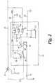
- the switch conventionally operates a warning light 21 (see Fig.2) in the cab 14.
- the handbrake switch 17 is conveniently used in the present invention as a handbrake condition sensor, although a separate handbrake condition sensor could be used if desired.
- the cab 14 also houses a handbrake "off" warning unit 22 which in use provides a vocal message warning that the handbrake is in an "off" condition.
- a handbrake warning system comprises the audible warning unit 22 which has a DC voltage operated audible warning means 23 having a power feed line 26 and is connected to ground through a groundline 25.
- the warning means 23 is supplied with a 24DC voltage which passes through a timer 24 and a change-over relay switch 45 which in turn is operated by a another change-over relay switch 35.
- the timer 24 operates to allow the DC supply to pass only for a predetermined time period.
- the timer 24 may be adjustable for setting different time periods.
- the timer 24 operates using 12V DC supply and is connected to the power feed line 26 via a line 28 and a resistor 27 which reduces the 24V supply to 12V.
- the timer 24 is also connected via line 31 and resistor 32 line to a 24V power supply line 33 which is live only when the vehicle ignition switch is activated.
- the resistor 32 again reduces the 24V supply to 12V for the timer.
- the timer 24 senses via the line 31 when the ignition is switched off and is thereby triggered to allow the 24V supply to the warning means 23 to continue for only a predetermined period.
- a 24V operable timer may be used if available.
- the handbrake warning light 21 is also supplied via an ignition switch activated line, conveniently the same line 33, and is connected to ground via the switch 17.
- the change-over relay switch 35 has its solenoid 36 connected to the timed power supply line 26 and to ground via ground line 37 and the handbrake switch 17.
- the relay switch 35 is also located in the power supply line 38 to the solenoid 46 of the second change-over relay 45.
- the solenoid 46 is connected to ground via the door pin switch 16.
- the change over relay switch 45 is located in the power supply line 26 to the warning means 23.
- the change-over relay 35 is operable so that its switch is closed when no power passes through its solenoid 36 and the relay 45 is operable so that its switch is closed when power is supplied to its solenoid 46.
- the warning means 23 is operable when the tractor cab door is opened and the handbrake lever 13 has not been operated to apply the brakes. Since the lever 13 is in an "off" condition the switch 17 is open and the relay 35 is closed.
- the time 24 will be activated if the ignition is switch off and the power supply to the warning means 23 will be cut after a predetermined time period.
- the warning means 23 may produce any vocal message to warn the driver however a short snappy pre-recorded vocal message is preferred, for example "Check Handbrake” or "Handbrake Off”.
- FIG.3 With reference to Fig.3, there is shown a circuit diagram for a second hand brake warning system which is formed on a printed circuit board.
- the circuit receives a 24v supply on feed line 51 which passes through a first voltage regulator 52 to provide an 18V supply on line 53 and second voltage regulator 54 to provide a 5V supply on line 55.
- the 18V supply line 53 is connected to the 18v input 71 of an audio system 72 and the line 55 is connected to a 5v supply line 56 for a microprocessor 57.
- the microprocessor 57 receives handbrake on/off signals via the terminals 58,59 respectively which are connected to a hand break warning switch 17 (see Fig.1) connected into an air line.
- the microprocessor 57 also receives driver's door open/closed signals via terminals 61,62, and is pre-programmed to operate the audio system 72 when the hand brake is in an "off condition" and the driver's door is open.
- the processor is programmed to cause the audio system to repeat the verbal message a desired number of times.
- the microprocessor 57 has output ports connected to the audio system 72, including the ports 63-69 which are connected through a multi-core cable 73, and further outputs which are connected to a dual colour LED warning devices 74 which indicate when the warning system is correctly connected and is in operation. Another LED 75 may be optionally connected in parallel with the dual colour LED 74 to provide a remote warning device.
- the audio system 72 has a sound chip 77 with inputs connected to the microprocessor 57.
- Inputs 81-87 connected via cable 73 locate the verbal message on the sound chip 77.
- the chip 77 has outputs 78 79 connected to a volume control 88 in turn connected to an amplifier 89 of an audio circuit 90 having outputs 91 connectable to a speaker 92.
Applications Claiming Priority (2)
| Application Number | Priority Date | Filing Date | Title |
|---|---|---|---|
| GB0126091A GB0126091D0 (en) | 2001-10-31 | 2001-10-31 | Handbrake condition indicator |
| GB0126091 | 2001-10-31 |
Publications (1)
| Publication Number | Publication Date |
|---|---|
| EP1308362A1 true EP1308362A1 (fr) | 2003-05-07 |
Family
ID=9924842
Family Applications (1)
| Application Number | Title | Priority Date | Filing Date |
|---|---|---|---|
| EP02257293A Withdrawn EP1308362A1 (fr) | 2001-10-31 | 2002-10-22 | Indicateur d'etat de frein de stationnement |
Country Status (2)
| Country | Link |
|---|---|
| EP (1) | EP1308362A1 (fr) |
| GB (2) | GB0126091D0 (fr) |
Cited By (2)
| Publication number | Priority date | Publication date | Assignee | Title |
|---|---|---|---|---|
| EP2816873A1 (fr) * | 2013-06-21 | 2014-12-24 | Rohm Co., Ltd. | Circuit de pilote de LED pour un témoin de frein de l'automobile avec détection d'ouverture et de court-circuit défaut |
| US11180121B2 (en) | 2019-07-22 | 2021-11-23 | Toyota Motor Engineering & Manufacturing North America, Inc. | Parking brake setting devices and systems for terminal tractors |
Families Citing this family (2)
| Publication number | Priority date | Publication date | Assignee | Title |
|---|---|---|---|---|
| GB2478771A (en) * | 2010-03-18 | 2011-09-21 | Pownall Security Systems Ltd | Warning installation for air spring park brake systems |
| DE102013011787A1 (de) * | 2013-07-15 | 2015-01-15 | Wabco Gmbh | Handbremsventil für Bremsanlagen von pneumatisch gebremsten Kraftfahrzeugen |
Citations (4)
| Publication number | Priority date | Publication date | Assignee | Title |
|---|---|---|---|---|
| GB2039117A (en) * | 1978-09-09 | 1980-07-30 | Walker H | An audible warning system for vehicles |
| DE3026770A1 (de) * | 1979-07-16 | 1981-02-12 | Nissan Motor | Audiowarneinrichtung fuer ein kraftfahrzeug |
| EP0149070A2 (fr) * | 1983-12-12 | 1985-07-24 | Knorr-Bremse Ag | Frein à main, ou frein de blocage pour véhicules |
| DE3410586A1 (de) * | 1983-12-20 | 1985-09-26 | Knorr-Bremse GmbH, 8000 München | Handbrems- bzw. feststellbremseinrichtung fuer fahrzeuge |
Family Cites Families (2)
| Publication number | Priority date | Publication date | Assignee | Title |
|---|---|---|---|---|
| JPS5790447A (en) * | 1980-11-21 | 1982-06-05 | Nissan Motor Co Ltd | Alarm unit of automatic speed change gear |
| US5015991A (en) * | 1990-03-27 | 1991-05-14 | Barr William A | Alarm system for vehicle automatic transmission |
-
2001
- 2001-10-31 GB GB0126091A patent/GB0126091D0/en not_active Ceased
-
2002
- 2002-10-22 GB GB0224474A patent/GB2381511A/en not_active Withdrawn
- 2002-10-22 EP EP02257293A patent/EP1308362A1/fr not_active Withdrawn
Patent Citations (4)
| Publication number | Priority date | Publication date | Assignee | Title |
|---|---|---|---|---|
| GB2039117A (en) * | 1978-09-09 | 1980-07-30 | Walker H | An audible warning system for vehicles |
| DE3026770A1 (de) * | 1979-07-16 | 1981-02-12 | Nissan Motor | Audiowarneinrichtung fuer ein kraftfahrzeug |
| EP0149070A2 (fr) * | 1983-12-12 | 1985-07-24 | Knorr-Bremse Ag | Frein à main, ou frein de blocage pour véhicules |
| DE3410586A1 (de) * | 1983-12-20 | 1985-09-26 | Knorr-Bremse GmbH, 8000 München | Handbrems- bzw. feststellbremseinrichtung fuer fahrzeuge |
Cited By (2)
| Publication number | Priority date | Publication date | Assignee | Title |
|---|---|---|---|---|
| EP2816873A1 (fr) * | 2013-06-21 | 2014-12-24 | Rohm Co., Ltd. | Circuit de pilote de LED pour un témoin de frein de l'automobile avec détection d'ouverture et de court-circuit défaut |
| US11180121B2 (en) | 2019-07-22 | 2021-11-23 | Toyota Motor Engineering & Manufacturing North America, Inc. | Parking brake setting devices and systems for terminal tractors |
Also Published As
| Publication number | Publication date |
|---|---|
| GB0126091D0 (en) | 2001-12-19 |
| GB0224474D0 (en) | 2002-11-27 |
| GB2381511A (en) | 2003-05-07 |
Similar Documents
| Publication | Publication Date | Title |
|---|---|---|
| US5198798A (en) | Wireless taillight system | |
| US20030030550A1 (en) | Child safety device for buses | |
| US6100801A (en) | Radio controlled light bar | |
| US7489236B2 (en) | Pedestrian alert system for vehicles | |
| EP3212464A1 (fr) | Procédé et dispositif permettant de faire fonctionner un véhicule et d'exploiter un parking | |
| US20070118261A1 (en) | Vehicle for simulating impaired driving | |
| US8816691B2 (en) | Trailer connection checking device and method | |
| US5281950A (en) | Vehicle U-turn signal system control | |
| US10053002B2 (en) | Trailer light check activation system | |
| EP1308362A1 (fr) | Indicateur d'etat de frein de stationnement | |
| US5389913A (en) | Warning system for vehicles | |
| US6989740B2 (en) | Advanced audio safety apparatus | |
| US7190258B2 (en) | Alarm for a livestock trailer and method of use thereof | |
| US20080231285A1 (en) | Trailer Lighting, Control and Signaling Circuits Tester | |
| US7137674B2 (en) | Reverse driving signal | |
| CA2412983A1 (fr) | Telecommande pour controleur electronique de frein de roue | |
| US20050146437A1 (en) | Alarm for a hydraulic system, hydraulic system, method of giving an alarm and vehicle incorporating a hydraulic system | |
| US5746284A (en) | Vehicle back-up safety device | |
| US20070188316A1 (en) | Parking brake off warning system | |
| US20180339568A1 (en) | System for safely kneeling a vehicle | |
| EP0269210B1 (fr) | Système de sécurité pour prevenir l'usage non-autorisé des hayons élévateurs à moteur | |
| US20030098785A1 (en) | Vehicle back-up alarm sensor for electrical trailer contact | |
| US4825190A (en) | Safety system for preventing the unauthorized use of powered liftgates | |
| US20020135230A1 (en) | Vehicle safety feature | |
| US6031295A (en) | Automatic siren disrupter |
Legal Events
| Date | Code | Title | Description |
|---|---|---|---|
| PUAI | Public reference made under article 153(3) epc to a published international application that has entered the european phase |
Free format text: ORIGINAL CODE: 0009012 |
|
| AK | Designated contracting states |
Designated state(s): AT BE BG CH CY CZ DE DK EE ES FI FR GB GR IE IT LI LU MC NL PT SE SK TR |
|
| AX | Request for extension of the european patent |
Extension state: AL LT LV MK RO SI |
|
| AKX | Designation fees paid | ||
| REG | Reference to a national code |
Ref country code: DE Ref legal event code: 8566 |
|
| STAA | Information on the status of an ep patent application or granted ep patent |
Free format text: STATUS: THE APPLICATION IS DEEMED TO BE WITHDRAWN |
|
| 18D | Application deemed to be withdrawn |
Effective date: 20031110 |