EP1308320A2 - Verfahren zur Ermittlung sich anbahnender Laufstreifenablösung eines Luftreifens bei einem Fahrzeug - Google Patents
Verfahren zur Ermittlung sich anbahnender Laufstreifenablösung eines Luftreifens bei einem Fahrzeug Download PDFInfo
- Publication number
- EP1308320A2 EP1308320A2 EP02015974A EP02015974A EP1308320A2 EP 1308320 A2 EP1308320 A2 EP 1308320A2 EP 02015974 A EP02015974 A EP 02015974A EP 02015974 A EP02015974 A EP 02015974A EP 1308320 A2 EP1308320 A2 EP 1308320A2
- Authority
- EP
- European Patent Office
- Prior art keywords
- wheel
- determined
- speed output
- output signal
- signal
- Prior art date
- Legal status (The legal status is an assumption and is not a legal conclusion. Google has not performed a legal analysis and makes no representation as to the accuracy of the status listed.)
- Granted
Links
Images






Classifications
-
- B—PERFORMING OPERATIONS; TRANSPORTING
- B60—VEHICLES IN GENERAL
- B60C—VEHICLE TYRES; TYRE INFLATION; TYRE CHANGING; CONNECTING VALVES TO INFLATABLE ELASTIC BODIES IN GENERAL; DEVICES OR ARRANGEMENTS RELATED TO TYRES
- B60C23/00—Devices for measuring, signalling, controlling, or distributing tyre pressure or temperature, specially adapted for mounting on vehicles; Arrangement of tyre inflating devices on vehicles, e.g. of pumps or of tanks; Tyre cooling arrangements
- B60C23/06—Signalling devices actuated by deformation of the tyre, e.g. tyre mounted deformation sensors or indirect determination of tyre deformation based on wheel speed, wheel-centre to ground distance or inclination of wheel axle
- B60C23/061—Signalling devices actuated by deformation of the tyre, e.g. tyre mounted deformation sensors or indirect determination of tyre deformation based on wheel speed, wheel-centre to ground distance or inclination of wheel axle by monitoring wheel speed
- B60C23/062—Frequency spectrum analysis of wheel speed signals, e.g. using Fourier transformation
-
- B—PERFORMING OPERATIONS; TRANSPORTING
- B60—VEHICLES IN GENERAL
- B60C—VEHICLE TYRES; TYRE INFLATION; TYRE CHANGING; CONNECTING VALVES TO INFLATABLE ELASTIC BODIES IN GENERAL; DEVICES OR ARRANGEMENTS RELATED TO TYRES
- B60C23/00—Devices for measuring, signalling, controlling, or distributing tyre pressure or temperature, specially adapted for mounting on vehicles; Arrangement of tyre inflating devices on vehicles, e.g. of pumps or of tanks; Tyre cooling arrangements
- B60C23/06—Signalling devices actuated by deformation of the tyre, e.g. tyre mounted deformation sensors or indirect determination of tyre deformation based on wheel speed, wheel-centre to ground distance or inclination of wheel axle
- B60C23/061—Signalling devices actuated by deformation of the tyre, e.g. tyre mounted deformation sensors or indirect determination of tyre deformation based on wheel speed, wheel-centre to ground distance or inclination of wheel axle by monitoring wheel speed
-
- G—PHYSICS
- G01—MEASURING; TESTING
- G01M—TESTING STATIC OR DYNAMIC BALANCE OF MACHINES OR STRUCTURES; TESTING OF STRUCTURES OR APPARATUS, NOT OTHERWISE PROVIDED FOR
- G01M17/00—Testing of vehicles
- G01M17/007—Wheeled or endless-tracked vehicles
- G01M17/02—Tyres
-
- B—PERFORMING OPERATIONS; TRANSPORTING
- B60—VEHICLES IN GENERAL
- B60C—VEHICLE TYRES; TYRE INFLATION; TYRE CHANGING; CONNECTING VALVES TO INFLATABLE ELASTIC BODIES IN GENERAL; DEVICES OR ARRANGEMENTS RELATED TO TYRES
- B60C19/00—Tyre parts or constructions not otherwise provided for
- B60C2019/005—Magnets integrated within the tyre structure
Definitions
- the invention relates to a method for determining impending tread detachments of a pneumatic tire on a vehicle
- DE 199 08 701 A1 describes a system for Detection of a so-called emergency running condition is known that a tire with Emergency running support body presupposes, wherein the support body has unbalances caused by Generate frequencies in contact with the inside of the tire when the tire is depressurized, which as an interference signal by a sensor, in particular by a conventional ABS system are detectable.
- the US 6 deals with the problem of impending tread detachment 028 508 B1.
- a sensor in the form of a laser is proposed, which is based on the A tire tread is aligned. Do bulges or bubbles develop on the Tread, the laser recognizes this by changing the distance between Tread and laser.
- Such an arrangement is relatively complex and expensive because a laser source must be assigned to each wheel, for example within the wheel housing. Here, too, dirt and foreign matter can accumulate between the profile blocks Lead to misinterpretations.
- one or more separately defined tread detachments that are characteristic and are Wheel speed proportional periodic vibrations of the first vibration or the Speed output signal are superimposed, and wherein the signal processing device a superposition of the first periodic vibration with the one or more separately defined characteristic of periodic tread detachments that are in the offing Vibration (s) is detected and processed into a warning signal.
- tread detachments that are characteristic and are Periodic vibrations proportional to the wheel speed become an exclusive feature initiating tread detachments to create a specific characteristic which independent of influencing factors such as speed, wheel load, tire wear, Road surface, etc. provides a clearly recognizable signal. When such occurs Signals can therefore undoubtedly be more likely to arise Tread detachments are closed without further checks of the Driving state must take place. In many cases this is already the case for reliable recognition Superposition of the speed output signal with only a second one that is approaching Tread detachments characteristic and periodic proportional to the wheel speed Vibration sufficient.
- the speed output signal is advantageously in the form of a permanent existing first periodic and proportional to the wheel speed vibration active or passive magnetic field sensors are provided, rotating relative to the latter magnetically active or passive and on rotating or fixed wheels Parts of the vehicle, preferably encoders, one for Generate periodic magnetic field change proportional to wheel speed.
- the separately defined ones are initiated Tread detachments characteristic and periodic proportional to the wheel speed Generates vibrations.
- the speed output signal of a wheel or an axle after processing in the signal processing device with speed output signals the other wheels or axles are compared as reference values. This on the one hand leads to the localization of impending tread detachments and further excludes that disturbances acting on all wheels at the same time, in particular in the event of a short-term occurrence, do not trigger a warning signal.
- the comparison can here with wheels of a vehicle side, a vehicle axle or in the form of a Comparisons can be made with diagonally opposite wheels.
- the basis for the determination or for the processing of the corresponding times for the partial rotations of the wheel determined by the defined wheel rotation angles is a “time window”, namely a defined counting time or measuring time T L , also called “loop time”.
- Such a determination of the wheel speed only involves a relatively simple processing of the speed output signal and thus reduces the expenditure on electronic processing devices or computing capacity and thus the costs for the corresponding electronics.
- a processing method of the speed output signal it must be taken into account that when evaluating the number of individual pulses received within a defined counting time T L , body or body vibrations or resonances also influence the evaluation result - without necessarily weakening its significance - and change so that a balance must be made between the simplest possible evaluation and the most accurate evaluation result.
- the superimposed separate additional vibrations which are characteristic of tread strip detachments are represented as speed vibrations, i.e. as periodic speed changes within one wheel revolution, which are generated by the rolling tread detachments which change in differently small time intervals due to the unwinding radius.
- speed vibrations i.e. as periodic speed changes within one wheel revolution
- These vibrations cause a clearly noticeable change in the number of counting pulses determined from the binary signal within the counting interval T L (loop time).
- the basis for determining or processing the corresponding one Times for the partial rotations of the wheel determined by the defined wheel rotation angle not a "time window", but the partial rotation of the wheel as such, i.e. so the Consideration of a defined wheel rotation angle or an "angle window".
- the The measurement can then usually require digital input signals for processing the times for the partial rotations of the wheel determined by the defined wheel rotation angles by determining the edge distance, i.e. the time differences between the edges of the square wave signal. It makes sense to look at such Evaluation of a square wave, the edge distance or the time difference between the zero crossings of the edges of the square wave signal, i.e. always at one representative and same place of the signal.
- any other can be used instead of a square wave prepared vibration to determine the corresponding times for partial rotations of the Rades are used.
- the times for partial rotations of the wheel are thus measured directly via the time differences between the zero crossings (zero crossing times), ie the time intervals ⁇ T 0 (i) (t) between the edges of a square wave, with ⁇ T 0 the zero crossing time for the determinations / Represents measurements i, i + 1, i + 2 etc.
- averaging according to feature b) there is in addition to the averaging of several successively ascertained or calculated values of a wheel revolution a particularly suitable type of evaluation in that the individual times determined for the partial rotations of the wheel determined by the defined wheel rotation angle before further processing is first subjected to a rotationally synchronous averaging of the type be that over several wheel revolutions from the in relation to one wheel revolution in same time intervals or times measured in the same rotation angle intervals Mean value for several wheel revolutions is formed, then the further one Signal processing is based.
- Such a kind of averaging is also suitable for both those already mentioned Evaluation based on the defined counting times (loop time) as well as for others a processing of the speed output signal resulting values, for example for the Frequencies, wheel speeds, etc., as will be described below.
- the factor 0.5 results from the two measured zero crossing times for one oscillation period of the sinusoidal speed output signal of a wheel.
- Feature c) in addition to averaging several consecutive determined or calculated values of a wheel revolution a rotationally synchronous averaging provided in which the recorded on the wheel and after processing already as "Frequency values" present signals that are the same with respect to one wheel revolution Angle of rotation intervals are recorded, averaged over several wheel revolutions become.
- This allows, as already shown, the influence of signal noise or Reduce short-term disturbances, such as bumps on the road, etc. and amplify the meaningfulness of the signal, since the then conspicuous frequency of the impending tread detachment characteristic, separately defined vibration, for example, formed as a harmonic vibration of the n-th order of the tire period, is clearly noticeable from the influences usually generated by other disturbance variables different.
- Such a frequency analysis can be carried out, for example, in the form of a Fourier analysis be what both by a computing unit and - analog - by a Circuit arrangement can take place.
- Such evaluations or procedures can each be used alone or in addition to Evaluation of the standard deviations of the zero crossing times can be carried out.
- the Evaluations of the frequency analysis and the subsequent integration via selected Frequency intervals offer the advantage that the reliability of the information is further increased can be because the then striking order of the frequency of the approaching Tread detachment characteristic, separately defined vibration, for example designed as a harmonic vibration of the n-th order of the tire period, on simple Way can be determined, since it differs from that usually by other disturbance variables generated influences even more clearly.
- the rolling circumference of the wheel / tire during the zero crossing time is 0.02 m in this case.
- Such an evaluation of the wheel speeds differentiates in terms of the determination method from the one already mentioned and on the evaluation of the times for the partial rotations of the wheel within a "loop time", since here for the determination or processing of the corresponding times for the Defined wheel rotation angle, certain partial rotations are based on the partial rotation of the wheel as such, that is to say the consideration of a defined wheel rotation angle.
- Both process training courses namely that of speed analysis and that of Acceleration analysis can be used alone or in addition to the evaluation of the Standard deviations of zero crossing times or frequencies / frequency analysis be performed, with each additional or additional and on the input or Intermediate size "zero crossing times" based evaluation advantages with regard to a offers increased information security.
- speed output signals are checked against several threshold values, after which with high Certainty the occurrence of an emerging tread detachment characteristic vibration can be distinguished from any disturbance variables.
- the toothed magnet wheels or contain similar elements as encoders all evaluation methods also as such be formed that misinterpretations of the signal by any existing Gearing pitch errors or other tolerances in the mechanical elements or in the electronic components can be avoided by processing the Signals include "learning" and self-calibration of the overall system. This can e.g. in that in the normal state, i.e. when driving without a looming end Tread detachments, regular deviations detected and their Signal portion are deducted from the determined base signal.
- a method for determining upcoming is particularly advantageous Tire detachments of a pneumatic tire for vehicle wheels within a control system
- a control system Use for pneumatic vehicle wheels, especially within an anti-lock braking system (ABS), preferably by the control system at least on each axis on each wheel, a permanent first periodic and the wheel speed proportional vibration generated and as a speed output signal Signal processing device of the control system is fed, where looming Tread detachments a separately defined tread detachment that is in the offing characteristic second periodic vibration proportional to the wheel speed first vibration or the speed output signal is superimposed, and wherein the Signal processing device of the control system an overlay of the first periodic vibration with the separate second periodic vibration is detected and processed into a warning signal for upcoming tread detachments.
- ABS anti-lock braking system
- the calculated Mean value is first adjusted for a first reference value, which Manufacturing tolerances of the ABS signal transmitter (encoder) represented for the respective wheel.
- the Air pressure inside tire decreases as tread detachments begin to emerge.
- the change in Air pressure in particular the reduction in pressure, can have a negative impact on the characteristic signal impact in that this signal or frequency is equalized and is therefore not recorded as a deviation.
- a simultaneous Detection of the tire pressure can therefore be used as a correlation variable, to capture dangerous conditions. This is especially what according to another advantageous embodiments of the invention can be provided that the Pressure detection device determined pressure value in correlation to the speed output signal brought.
- DDS Deflation Detection System
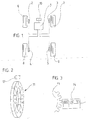
- FIG. 1 the arrangement of a device according to the invention within a Represents a motor vehicle, shows a central computer or evaluation unit 1, the is connected to sensor devices 2-5, which in turn the individual wheels 6-9 assigned.
- the sensor devices detect the speed output signals of the individual wheels and forward them to the central computer unit, which has a Display and warning device 10 is connected, for example, to a driver's field of vision Dashboard arranged optical warning indicator.
- the central computer unit contains a signal processing unit with all of them Devices for evaluating and comparing the speed output signals from the individual wheels and for generating a warning signal in the display device 10.
- FIG. 2 shows the basic illustration of the device in the device according to the invention used and known sensor device, each with an active Transmitter device in the form of a magnet wheel 11 rotating with the respective wheel which generates a periodic magnetic field change in the magnetic field sensor 12, the as a speed output signal in the form of a periodic proportional to the wheel speed Vibration in the signal processing device belonging to the central computer unit is evaluated and processed.
- FIG 3 shows a schematic representation of an alternative and also in the prior art Technology existing sensor device, here a passive transmitter device in the form of a toothed metallic wheel 13 is present on its circumference, the speed is detected via a magnetic field sensor 14 designed for this purpose.
- FIG. 4 shows another known alternative of a sensor device in principle Representation, again with an active transmitter device in the form of Tire sidewall 15 arranged permanent magnetic areas 16 are arranged. The speed of a tire equipped in this way is then controlled by a appropriately designed magnetic field sensor 17 is detected.
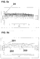
- FIG. 5a shows a diagram which shows the evaluation of the wheel speeds of the individual wheels processed in the signal processing device and determined with the aid of the sensor devices via the wheel speed within defined counting times T L (loop time).
- the defined beat times are shown here on the abscissa, while the ordinate shows the Includes wheel speeds of the individual wheels.
- FIG. 5b is an enlarged representation (magnifying glass) of the time interval 24 marked in FIG. 5a represents.
- FIGS. 5a and 5b show the evaluation according to the method for a vehicle, whose left rear wheel (RL) shows looming tread detachments.
- the speed curve of the left Rear wheel representing speed curve 200, the characteristics of which by a periodic vibration that is separately defined and proportional to the wheel speed is generated, can be easily and with conventional means by reference or threshold values 201 and Check 202 for the wheel speed and as an impending tread detachment detect representative speed curve, even if this is due to bodywork or Structure vibrations and resonances is affected.
- Figures 6a and 6b and 7a - 7e show the clear recognizability of a speed output signal overlaid for upcoming tread detachments characteristic and separately defined vibration proportional to the wheel speed, the generated by typical irregularities in the form of unbalances.
- FIG. 6a initially shows these basic and only qualitative representations the time behavior of a normal speed output signal represented by curve 203, for example an ABS signal at a constant speed without impending tread detachments, i.e. in normal condition.
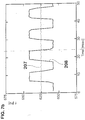
- FIG. 7a shows the determined times plotted over a time axis for the partial rotations of the wheel determined by the defined wheel rotation angles in the form of a zero crossing time signal ⁇ T 0 (i) (t) of the normal and the superimposed speed output signal according to FIG. 6b on the basis of curves 205 and 206, which was determined with the aid of a time control device (timer) measuring the times / time differences between the zero crossings of the individual pulses obtained.
- time control device timer
- Fig. 6b substantially constant according to curve 205 remain at around 0.8 msec, apart from slight fluctuations disruptive influences, such as those caused by changes in speed, Road surface, signal noise etc. can arise.
- Fig. 7a It is also clear here that the frequencies determined for the zero crossing times of the normal speed output signal acc. 6b remain essentially constant in accordance with curve 207 and in this case lie at approximately 625 Hz, apart from again disturbing influences which only show slight fluctuations.
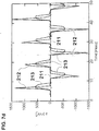
- FIG. 7d shows the plotted on a time axis and according to the wheel speeds.
- Curve 213 shows the wheel accelerations of curve 212 filtered by averaging. Such filtering can occasionally make sense, since due to the roughening character of a differentiation, the acceleration curves are often particularly noisy, so that a more reliable and easier evaluation can take place after filtering.
- FIG. 7e shows that with the aid of a frequency analysis of the zero crossing time signal gem. 7a, namely here with the aid of a fast Fourier transform (FFT) spectral density, plotted against frequency.
- FFT fast Fourier transform
- an averaging was carried out here over six successive calculations of the zero crossing times (six edge signals).
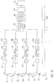
- FIG. 8 shows a schematic representation of a signal processing of a device according to the invention as a flowchart based on the method-based evaluation of the numbers of the individual pulses received within a defined counting time T L (loop time) of the normal or superimposed speed output signal, with the processing scheme shown here
- An average wheel rotation speed within defined counting times T L and including several successive wheel turning angles is determined from the times determined for the partial rotations and their number for one or more wheel rotations within the counting times T L (loop time).
- the front left of the individual wheels (FL) are shown schematically here right (FR), rear left (RL) and rear right (RR) sensor devices arranged, the from the active transmitter devices 27-30 designed as pole wheels according to FIG. 2a and the associated magnetic field sensors 31-34.
- the speed output signals detected by the sensor devices are then on the signal processing device 100 belonging to the central computer unit 1 forwarded and here with the help of the low-pass filter 35-38 of high-frequency noise components filtered, after which the vibration representing the speed output signal via Schmitt trigger 39-42 is converted into a square wave signal from individual pulses.
- the resulting individual impulses from the speed output signals of the individual Wheels then arrive at the time control devices 43 to 46 (timers), which are used for several successive and defined wheel rotation angles the corresponding times for the measure the defined wheel rotation angles of certain partial rotations of the wheel, the Measuring the times by determining the time differences (zero crossing times) between two ascending or descending and with the times for the partial rotations correlating edges of the rectangular signal.
- the individual pulses of the square-wave signal are fed to the counting devices 43 'to 46' to determine the number n (T L ) of the individual pulses received or the measured times within a defined counting time T L
- the averaged wheel rotation speeds are then in a comparison device 49 compared with reference and / or threshold values, the comparison device at Exceeding a predetermined difference to the reference and / or threshold values sends a signal to the display device 10, which is in the driver's field of vision Dashboard is arranged.
- the central computer unit 1 contains no further details here Devices for power supply and line, possibly for signal amplification and Signal transmission, cooling devices etc., as is usually the case in such microcomputers designated units are available and necessary.
- the time control devices 43 to 46 and the counting devices 43 'to 46' can here, too, just like those shown in FIGS. 9 and 10 Time control devices (timers), each designed as a "multiplex" device, which in short time intervals the individual speed output signals of the axes or Wheels processed one after the other in time.
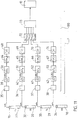
- FIG. 9 shows a schematic representation of a signal processing of a device according to the invention based on the evaluation of the zero crossing times ⁇ T 0 (i) (t) according to the method, in which the times for partial rotations of the wheel are measured directly via the time differences between the zero crossings (zero crossing times) , ie the time intervals ⁇ T 0 (i) (t) between the edges of a square wave, where ⁇ T 0 represents the zero crossing time for the determinations / measurements i, i + 1, i + 2 etc.
- the individual pulses obtained in each case from the speed output signals of the individual wheels then arrive at the time control devices 50 to 53 (timers), which measure the corresponding times for several successive and defined wheel rotation angles for the partial rotations of the wheel determined by the defined wheel rotation angles, the measurement of the Times are determined by determining the time differences ⁇ T 0 (i) (t) between two ascending or descending flanks of the rectangular signal (zero crossing times) which correlate with the times for the partial rotations.
- the deviations in the times for the Partial turns of the wheel here for one or more wheel turns calculated mean values of the times for the partial rotations of the wheel or Zero crossing times of several successive measurements determined and one Comparison device 56 supplied, which the determined deviations with reference and / or Compares threshold values and when a predetermined difference is exceeded a warning signal to the warning device 10 for the reference and / or threshold values emits, which in turn is arranged in the driver's field of vision in the dashboard.
- FIG. 10 shows a schematic representation of the signal processing of a Device according to the invention as a flow chart, in which one on the reciprocal formation based calculation of the frequencies of several successive measurements of the Zero crossing times take place.
- the speed output signals detected by the sensor devices are then on the signal processing device 100 belonging to the central computer unit 1 forwarded and here with the help of the low-pass filter 35-38 of high-frequency noise components filtered, after which the vibration representing the speed .output signal via Schmitt trigger 39-42 is converted into a square wave signal from individual pulses.
- the individual pulses obtained in each case from the speed output signals of the individual wheels then arrive at the time control devices 50 to 53 (timers), which measure the corresponding times for several successive and defined wheel rotation angles for the partial rotations of the wheel determined by the defined wheel rotation angles, the measurement of the Times are determined by determining the time differences ⁇ T 0 (i) (t) between two ascending or descending flanks of the rectangular signal (zero crossing times) which correlate with the times for the partial rotations.
- the factor 0.5 results from the two measured zero crossing times for one oscillation period of the here sinusoidal speed output signal of a wheel.
- the deviations in the frequencies of the mean values of the calculated here for one or more wheel revolutions Frequencies calculated for several successive frequency determinations and one Comparison device 63 is supplied, which the determined deviations with reference and / or Compares threshold values and when a predetermined difference is exceeded a warning signal to the reference and / or threshold values in the driver's field of vision arranged warning device 10 outputs.
- FIG. 11 shows a schematic representation of the signal processing of a Device according to the invention as a flowchart, in which the Frequency spectrum of the zero crossing times as a function of time (Zero crossing time signal) of a frequency analysis to determine the spectral Power spectral density is subjected.
- the speed output signals detected by the sensor devices are then on the signal processing device 100 belonging to the central computer unit 1 forwarded and here with the help of the low-pass filter 35-38 of high-frequency noise components filtered, after which the vibration representing the speed .output signal via Schmitt trigger 39-42 is converted into a square wave signal from individual pulses.
- the individual pulses obtained in each case from the speed output signals of the individual wheels then arrive at the time control devices 50 to 53 (timers), which measure the corresponding times for several successive and defined wheel rotation angles for the partial rotations of the wheel determined by the defined wheel rotation angles, the measurement of the Times are determined by determining the time differences ⁇ T 0 (i) (t) between two ascending or descending flanks of the rectangular signal (zero crossing times) which correlate with the times for the partial rotations.
- the frequency spectrum of the zero crossing time signal thus obtained is then fed to the computing units 64-67, in which a frequency analysis FT ( ⁇ T 0 ) is carried out in the form of a Fourier transformation to determine the spectral power density.
- a frequency analysis FT ( ⁇ T 0 ) is carried out in the form of a Fourier transformation to determine the spectral power density.
- the spectral power densities of the correspondingly processed respective speed output signals of the individual wheels in the computing units 68-71 are subjected to integration over certain frequency ranges, so that there is a value of the expression for the integral ⁇ FT ( ⁇ T 0 ) df ⁇ I f ( i ) results.
- the integral values I f FL (i) , I f FR (i) , I f RL (i) , and I f RR (i) thus determined with regard to the respective speed output signals of the individual wheels are then first of all stored in a memory 72 and then fed to a comparison device 73 which compares the determined integral values with reference and / or threshold values and, when a predetermined difference to the reference and / or threshold values is exceeded, emits a warning signal to the warning device 10 arranged in the driver's field of vision.
Landscapes
- Physics & Mathematics (AREA)
- Engineering & Computer Science (AREA)
- Mechanical Engineering (AREA)
- Mathematical Physics (AREA)
- General Physics & Mathematics (AREA)
- Measuring Fluid Pressure (AREA)
- Control Of Driving Devices And Active Controlling Of Vehicle (AREA)
- Measurement Of Mechanical Vibrations Or Ultrasonic Waves (AREA)
Abstract
Description
- Fig. 1
- eine Prinzipskizze zur Anordnung einer erfindungsgemäßen Vorrichtung innerhalb eines Kraftfahrzeuges
- Fig. 2
- eine prinzipielle Darstellung einer im Stand der Technik vorhandenen und mit einer aktiven Gebereinrichtung versehenen Sensoreinrichtung für die Raddrehzahl
- Fig. 3
- eine prinzipielle Darstellung einer im Stand der Technik vorhandenen und mit einer passiven Gebereinrichtung versehenen Sensoreinrichtung für die Raddrehzahl
- Fig. 4
- eine prinzipielle Darstellung einer im Stand der Technik vorhandenen und mit einer aktiven Gebereinrichtung in Form von in der Reifenseitenwand angeordneten permanentmagnetischen Arealen versehenen Sensoreinrichtung für die Raddrehzahl
- Fig. 5a
- ein Diagramm, welches die Auswertung der verarbeiteten und mit Hilfe der Sensoreinrichtungen über die Raddrehzahl ermittelten Radgeschwindigkeiten der einzelnen Räder innerhalb definierter Zählzeiten (Loops) zeigt
- Fig. 5b
- ein vergrößerte Darstellung (Lupe) des in Fig. 5a markierten Zeitintervalls
- Fig. 6a
- das Zeitverhalten einer ungestörten und mit Hilfe von Sensoreinrichtungen ermittelten und zur Raddrehzahl proportionalen Schwingung (normales Drehzahl-Ausgangssignal) bei konstanter Geschwindigkeit
- Fig. 6b
- das Zeitverhalten einer mit Hilfe von Sensoreinrichtungen ermittelten und zur Raddrehzahl proportionalen Schwingung mit überlagerter Schwingung n-ter Ordnung der Reifenperiode (überlagertes Drehzahl-Ausgangssignal) im Vergleich zum normalen Drehzahl-Ausgangssignal gem. Fig. 6a ,
- Fig. 7a
- die über einer Zeitachse aufgetragenen Nulldurchgangszeiten ΔT0 (i) (t) (Nulldurchgangszeiten-Signal) des normalen und des überlagerten Drehzahl-Ausgangssignales gem. Fig. 6b, die mit Hilfe einer die Zeitdifferenzen zwischen den Nulldurchgängen der erhaltenen Einzelimpulse messenden Zeitkontrolleinrichtung (Timer) ermittelt wurden,
- Fig. 7b
- die über einer Zeitachse aufgetragenen und durch Kehrwertbildung aus den Nulldurchgangszeiten gem. Fig. 7a ermittelten Frequenzen,
- Fig. 7c
- die über einer Zeitachse aufgetragene und aus den Nulldurchgangszeiten gem. Fig. 7a errechnete Radgeschwindigkeit,
- Fig. 7d
- die über einer Zeitachse aufgetragene und aus den Radgeschwindigkeiten gem. Fig. 7c errechnete Radbeschleunigung,
- Fig. 7e
- die mit Hilfe einer Frequenzanalyse des Nulldurchgangszeiten-Signales gem. Fig. 7a ermittelte spektrale Leistungsdichte, aufgetragen über der Frequenz,
- Fig. 7f
- die über einer Zeitachse aufgetragene und aus den Nulldurchgangszeiten errechneten Radgeschwindigkeiten aller vier Räder nach Auswertung realer und am fahrenden Fahrzeug aufgenommener Drehzahl-Ausgangssignale,
- Fig. 8
- eine schematische Darstellung einer auf der verfahrensgemäßen Auswertung der Anzahlen der erhaltenen Einzelimpulse innerhalb einer definierten Zählzeit TL (Loop-Time) des normalen bzw. überlagerten Drehzahl-Ausgangssignales beruhenden Signalverarbeitung einer erfindungsgemäßen Vorrichtung als Ablaufplan
- Fig. 9
- eine schematische Darstellung einer auf der verfahrensgemäßen Auswertung der Nulldurchgangszeiten ΔT0(i) (t) beruhenden Signalverarbeitung einer erfindungsgemäßen Vorrichtung als Ablaufplan
- Fig. 10
- eine schematische Darstellung der Signalverarbeitung einer erfindungsgemäßen Vorrichtung als Ablaufplan, bei der eine auf der Kehrwertbildung beruhende Berechnung der Frequenzen mehrerer aufeinanderfolgender Messungen der Nulldurchgangszeiten erfolgt
- Fig. 11
- zeigt eine schematische Darstellung der Signalverarbeitung einer erfindungsgemäßen Vorrichtung als Ablaufplan, bei der mit Hilfe einer Recheneinheit das Frequenzspektrum der Nulldurchgangszeiten in Abhängigkeit von der Zeit (Zeiten-Signal) einer Frequenzanalyse zur Ermittlung der spektralen Leistungsdichte (power spectral density) unterzogen wird
- 1
- zentrale Recheneinheit
- 2-5
- Sensoreinrichtung
- 6-9
- Rad
- 10
- Anzeigeeinrichtung
- 11
- Polrad
- 12
- Magnetfeldsensor
- 13
- gezahntes Rad / Gebereinrichtung
- 14
- Magnetfeldsensor
- 15
- Reifenseitenwand
- 16
- permanentmagnetische Areale
- 17
- Magnetfeldsensor
- 24
- Zeitintervall
- 25
- ---
- 26
- ---
- 27-30
- aktive Gebereinrichtung
- 31-34
- Magnetfeldsensor
- 35-38
- Tiefpaß-Filter
- 39-42
- Schmitt-Trigger
- 43-46
- Zeitkontrolleinrichtung
- 43'-46'
- Zähleinrichtung
- 47
- Speicher
- 48
- Rechnerschaltung
- 49
- Vergleichseinrichtung
- 50-53
- Zeitkontrolleinrichtung (Timer)
- 54
- Speicher
- 55
- Rechnerschaltung
- 56
- Vergleichseinrichtung
- 57-60
- Recheneinheit zur Frequenzbestimmung mittels Kehrwertbildung
- 61
- Speicher
- 62
- Rechnerschaltung
- 63
- Vergleichseinrichtung
- 64-67
- Recheneinheit zur Durchführung einer Fourrier-Transformation
- 68-71
- Recheneinheit zur Durchführung einer Integration
- 72
- Speicher
- 73
- Vergleichseinrichtung
- 100
- Signalverarbeitungseinrichtung
- 200
- Geschwindigkeitskurve
- 201, 202
- Referenz- oder Schwellenwert
- 203
- Zeitverhalten des normalen Drehzahl-Ausgangssignales
- 204
- Zeitverhalten des überlagerten Drehzahl-Ausgangssignales
- 205
- Nulldurchgangszeiten-Signal des normalen Drehzahl-Ausgangssignales
- 206
- Nulldurchgangszeiten-Signal des überlagerten Drehzahl-Ausgangssignales
- 207
- Frequenzen der Nulldurchgangszeiten des normalen Drehzahl-Ausgangssignales
- 208
- Frequenzen der Nulldurchgangszeiten des überlagerten Drehzahl-Ausgangssignales
- 209
- aus dem normalen Drehzahl-Ausgangssignal ermittelte Radgeschwindigkeiten
- 209' - 209"'
- aus dem normalen Drehzahl-Ausgangssignal bei realem Fahrbetrieb ermittelte Radgeschwindigkeiten
- 210
- aus dem überlagerten Drehzahl-Ausgangssignal ermittelte Radgeschwindigkeiten
- 210'
- aus dem überlagerten Drehzahl-Ausgangssignal bei realem Fahrbetrieb ermittelte Radgeschwindigkeiten
- 211
- aus den Radgeschwindigkeiten des normalen Drehzahl-Ausgangssignales ermittelte Radbeschleunigungen
- 212
- aus den Radgeschwindigkeiten des überlagerten Drehzahl-Ausgangssignales ermittelte Radbeschleunigungen
- 213
- durch Mittelwertbildung gefilterte Radbeschleunigungen
- 214
- spektrale Leistungsdichte (normales Drehzahl-Ausgangssignal)
- 215
- spektrale Leistungsdichte (überlagertes Drehzahl-Ausgangssignal)
Claims (17)
- Verfahren zur Ermittlung sich anbahnender Laufstreifanablösungen eines Luftreifens an einem Fahrzeug, bei dem mindestens an jeder Achse, vorzugsweise an jedem Rad, eine permanent vorhandene erste periodische und zur Raddrehzahl proportionale Schwingung erzeugt und als Drehzahl- Ausgangssignal einer Signalverarbeitungsseinrichtung zugeleitet wird, und bei dem eine oder mehrere separat definierte, für sich anbahnende Laufstreifenablösungen charakteristische und zur Raddrehzahl proportionale periodische Schwingungen der ersten Schwingung bzw. dem Drehzahl-Ausgangssignal überlagert werden, und bei dem die Signalverarbeitungsseinrichtung eine Überlagerung der ersten periodischen Schwingung mit der/den separat definierten und für sich anbahnende Laufstreifenablösungen charakteristischen periodischen Schwingung(en) detektiert und zu einem Warnsignal verarbeitet werden.
- Verfahren nach Anspruch 1, bei dem mindestens an jeder Achse, vorzugsweise an jedem Rad, eine permanent vorhandene erste periodische und zur Raddrehzahl proportionale Schwingung erzeugt und als Drehzahl- Ausgangssignal einer Signalverarbeitungsseinrichtung zugeleitet wird, wobei das Drehzahl- Ausgangssignal durch aktive oder passive Magnetfeldsensoren bereitgestellt wird, indem relativ zu letzteren rotierende magnetisch aktive oder passive und an mit dem Rad drehenden oder an feststehenden Teilen des Fahrzeuges befindliche Einrichtungen, vorzugsweise Encoder, eine zur Raddrehzahl proportionale periodische Magnetfeldänderung erzeugen, und bei dem sich anbahnende Laufstreifenablösungen eine oder mehrere separat definierte, für sich anbahnende Laufstreifenablösungen charakteristische und zur Raddrehzahl proportionale periodische Schwingungen der ersten Schwingung bzw. dem Drehzahl-Ausgangssignal überlagert werden, und bei dem die Signalverarbeitungsseinrichtung eine Überlagerung der ersten periodischen Schwingung mit der/den separat definierten und für sich anbahnende Laufstreifenablösungen charakteristischen periodischen Schwingung(en) detektiert und zu einem Warnsignal verarbeitet werden.
- Verfahren nach Anspruch 1 oder 2, dadurch gekennzeichnet, daß das Drehzahl-Ausgangssignal nach einer Verarbeitung in der Signalverarbeitungsseinrichtung mit einem oder mehreren Referenz- und / oder Schwellenwerten verglichen und die Überlagerung mit den separaten und für sich anbahnende Laufstreifenablösungen charakteristischen periodischen Schwingungen anhand einer Überschreitung der Referenz- und / oder Schwellenwerte erkannt und zu einem Warnsignal verarbeitet wird.
- Verfahren nach Anspruch 3, dadurch gekennzeichnet, daß das Drehzahl-Ausgangssignal eines Rades oder einer Achse nach einer Verarbeitung in der Signalverarbeitungsseinrichtung mit Drehzahl-Ausgangssignalen der übrigen Räder oder Achsen als Referenzwerten verglichen wird.
- Verfahren nach Anspruch 3 oder 4, dadurch gekennzeichnet, daß in der Signalverarbeitungseinrichtung aus dem Drehzahl-Ausgangssignal die Radgeschwindigkeit für vorgegebene Zeitintervalle errechnet und mit einem oder mehreren Referenz- Radgeschwindigkeiten und / oder Schwellenwerten verglichen wird, wobei ausgehend von der das Drehzahl-Ausgangssignal repräsentierenden Schwingung in der Signalverarbeitungseinrichtunga) zunächst für mehrere aufeinanderfolgende und definierte Raddrehwinkel die entsprechenden Zeiten für die durch die definierten Raddrehwinkel bestimmten Teildrehungen des Rades ermittelt und gespeichert werden, und danachb) innerhalb von definierten und mehrere aufeinanderfolgende Raddrehwinkel beinhaltenden Zählzeiten TL aus den für die Teildrehungen ermittelten Zeiten und deren Anzahl eine mittlere Raddrehgeschwindigkeit für eine oder mehrere Radumdrehungen innerhalb der Zählzeiten errechnet und gespeichert wird, wonachc) die gemittelten Raddrehgeschwindigkeiten bzw. deren Verlauf mit Referenz- und /oder Schwellenwerten verglichen werden, wobeid) bei Überschreitung der Referenz- und / oder Schwellenwerte ein Warnsignal ausgegeben wird.
- Verfahren nach Anspruch 3 oder 4, dadurch gekennzeichnet, daß ausgehend von der das Drehzahl-Ausgangssignal repräsentierenden Schwingung in der Signalverarbeitungseinrichtunga) zunächst für mehrere aufeinanderfolgende und definierte Raddrehwinkel die entsprechenden Zeiten für die durch die definierten Raddrehwinkel bestimmten Teildrehungen des Rades ermittelt und gespeichert werden, und danachb) ein Mittelwert aus mehreren solchen aufeinanderfolgend ermittelten Zeiten für eine oder mehrere Radumdrehungen errechnet und gespeichert wird, wonachc) die Abweichungen der gem. a) ermittelten und gespeicherten Zeiten von dem gem. b) errechneten Mittelwert ermittelt werden, und danachd) die ermittelten Abweichungen mit Referenz- und / oder Schwellenwerten verglichen werden, wobeie) bei Überschreitung der Referenz- und / oder Schwellenwerte ein Warnsignal ausgegeben wird.
- Verfahren nach Anspruch 3 oder 4, dadurch gekennzeichnet, daß ausgehend von der das Drehzahl-Ausgangssignal repräsentierenden Schwingung in der Signalverarbeitungseinrichtunga) zunächst für mehrere aufeinanderfolgende und definierte Raddrehwinkel die entsprechenden Zeiten für die durch die definierten Raddrehwinkel bestimmten Teildrehungen des Rades ermittelt und gespeichert werden, und danachb) mit Hilfe einer oder mehrerer Recheneinheiten die Frequenzen der gem. a) ermittelten und gespeicherten Zeiten durch Kehrwertbildung errechnet und danach gespeichert werden, wobei anschließendc) ein Mittelwert der gem. b) ermittelten Frequenzen für eine oder mehrere Radumdrehungen errechnet und gespeichert wird, wonachd) die Abweichungen der gem. b) ermittelten und gespeicherten Frequenzen von dem gem. c) errechneten Mittelwert ermittelt werden, und danache) die ermittelten Abweichungen mit Referenz- und / oder Schwellenwerten verglichen werden, wobeif) bei Überschreitung der Referenz- und / oder Schwellenwerte ein Warnsignal ausgegeben wird.
- Verfahren nach Anspruch 3 oder 4, dadurch gekennzeichnet, daß ausgehend von der das Drehzahl-Ausgangssignal repräsentierenden Schwingung in der Signalverarbeitungseinrichtunga) zunächst für mehrere aufeinanderfolgende und definierte Raddrehwinkel die entsprechenden Zeiten für die durch die definierten Raddrehwinkel bestimmten Teildrehungen des Rades ermittelt und gespeichert werden, und danachb) mit Hilfe einer oder mehrerer Recheneinheiten das Frequenzspektrum der gem. a) ermittelten und gespeicherten Zeiten einer Frequenzanalyse zur Ermittlung der spektralen Leistungsdichte (power spectral density) unterzogen wird, wobei anschließendc) mit-Hilfe einer oder mehrerer Recheneinheiten die ermittelten spektralen Leistungsdichten einer Integration über bestimmte ausgewählte Frequenzintervalle unterzogen und danach gespeichert werden, wonachd) der Integralwert der ausgewählten Frequenzintervalle verglichen wird mit einem Referenz- oder Schwellenwert, unde) bei Überschreitung der Referenz- oder Schwellenwerte ein Warnsignal ausgegeben wird.
- Verfahren nach Anspruch 8, dadurch gekennzeichnet, daß als ausgewählte Frequenzintervalle genau solche verwendet werden, die einem Vielfachen der Raddrehfrequenz entsprechen, wobei vorzugsweise niedere Vielfache der Raddrehfrequenz (n = 1,2,3) betrachtet werden.
- Verfahren nach Anspruch 3 oder 4, dadurch gekennzeichnet, daß ausgehend von der das Drehzahl-Ausgangssignal repräsentierenden Schwingung in der Signalverarbeitungseinrichtunga) zunächst für mehrere aufeinanderfolgende und definierte Raddrehwinkel die entsprechenden Zeiten für die durch die definierten Raddrehwinkel bestimmten Teildrehungen des Rades ermittelt und gespeichert werden, und danachb) mit Hilfe einer oder mehrerer Recheneinheiten aus den gem. a) ermittelten und gespeicherten Zeiten die augenblicklichen Radgeschwindigkeiten errechnet und danach gespeichert werden, wobei anschließendc) ein Mittelwert der gem. b) ermittelten Radgeschwindigkeiten für eine oder mehrere Radumdrehungen errechnet und gespeichert wird, wonachd) die Abweichungen der gem. b) ermittelten und gespeicherten Radgeschwindigkeiten von dem gem. c) errechneten Mittelwert ermittelt werden, und danache) die ermittelten Abweichungen mit Referenz- und / oder Schwellenwerten verglichen werden, wobeif) bei Überschreitung der Referenz- und / oder Schwellenwerte ein Warnsignal ausgegeben wird.
- Verfahren nach Anspruch 3 oder 4, dadurch gekennzeichnet, daß ausgehend von der das Drehzahl-Ausgangssignal repräsentierenden Schwingung in der Signalverarbeitungseinrichtunga) zunächst für mehrere aufeinanderfolgende und definierte Raddrehwinkel die entsprechenden Zeiten für die durch die definierten Raddrehwinkel bestimmten Teildrehungen des Rades ermittelt und gespeichert werden, und danachb) mit Hilfe einer oder mehrerer Recheneinheiten aus den gem. a) ermittelten und gespeicherten Zeiten die augenblicklichen Radbeschleunigungen errechnet und danach gespeichert werden, wobei anschließendc) ein Mittelwert der gem. b) errechneten Radbeschleunigungen für eine oder mehrere Radumdrehungen errechnet und gespeichert wird, wonachd) die Abweichungen der gem. b) errechneten Radbeschleunigungen von dem gem. c) errechneten Mittelwert oder von einem Nullwert ermittelt werden, und danache) die ermittelten Abweichungen mit Referenz- und / oder Schwellenwerten verglichen werden, wobeif) bei Überschreitung der Referenz- und / oder Schwellenwerte ein Warnsignal ausgegeben wird.
- Verfahren nach Anspruch 6 bis 10, dadurch gekennzeichnet, daß die in einer oder mehreren Zeitkontrolleinrichtungen (Timer) gemessenen Zeitdifferenzen zwischen den Nulldurchgängen (Nulldurchgangszeiten) vor der weiteren Verarbeitung zunächst einer drehsynchronen Mittelung in der Art unterzogen werden, daß über mehrere Radumdrehungen aus den in Bezug auf eine Radumdrehung in gleichen Zeitintervallen bzw. in gleichen Drehwinkelintervallen gemessenen Nulldurchgangszeiten ein Mittelwert gebildet wird, der dann der weiteren Signalverarbeitung zugrunde liegt.
- Verwendung eines Verfahrens zur Ermittlung sich anbahnender Laufstreifanablösungen eines Luftreifens an einem Fahrzeug nach Anspruch 1 bis 12 innerhalb eines Kontrollsystems für luftbereifte Fahrzeugräder, insbesondere innerhalb eines Anti-Blockier-Systems (ABS), wobei durch das Kontrollsystem mindestens an jeder Achse, vorzugsweise an jedem Rad, eine permanent vorhandene erste periodische und zur Raddrehzahl proportionale Schwingung erzeugt und als Drehzahl-Ausgangssignal einer Signalverarbeitungseinrichtung des Kontrollsystems zugeleitet wird, wobei sich anbahnende Laufstreifenablösungen eine oder mehrere separat definierte, für sich anbahnende-Laufstreifenablösungen charakteristische und zur Raddrehzahl proportionale periodische Schwingungen der ersten Schwingung bzw. dem Drehzahl-Ausgangssignal überlagert werden, und bei dem die Signalverarbeitungsseinrichtung eine Überlagerung der ersten periodischen Schwingung mit der/den separat definierten und für sich anbahnende Laufstreifenablösungen charakteristischen periodischen Schwingung(en) detektiert und zu einem Warnsignal verarbeitet.
- Verwendung eines Verfahrens zur Ermittlung sich anbahnender Laufstreifanablösungen eines Luftreifens an einem-Fahrzeug nach Anspruch 13, dadurch gekennzeichnet, dass der errechnete Mittelwert zunächst um einen ersten Referenzwert bereinigt wird, welcher Fertigungstoleranzen des ABS-Signalgebers (Encoders) für das jeweilige Rad repräsentiert.
- Verfahren zur Ermittlung sich anbahnender Laufstreifanablösungen eines Luftreifens an einem Fahrzeug nach einem der Ansprüche 1 bis 14 dadurch gekennzeichnet, dass parallel zur Erfassung des Drehzahl-Ausgangssignals der Reifeninnendruck durch einen Druckerfasungseinrichtung ermittelt wird, wobei Abweichungen von einem vorgegebenen Sollwert um einen vorbestimmten Betrag zu einem für den Fahrer wahrnehmbaren Signal führen.
- Verfahren zur Ermittlung sich anbahnender Laufstreifanablösungen eines Luftreifens an einem Fahrzeug nach Anspruch 15, dadurch gekennzeichnet, dass der durch die Druckerfassungseinrichtung ermittelte Druckwert in Korrelation zum Drehzahl-Ausgangssignal gebracht wird.
- Verfahren zur Ermittlung sich anbahnender Laufstreifanablösungen eines Luftreifens an einem Fahrzeug nach Anspruch 16, dadurch gekennzeichnet, dass als Druckerfassungseinrichtung ein Deflation Detection System (DDS) verwendet wird, bei welchem luftdruckbedingte Veränderungen des Abrollumfangs des Reifens ermittelt werden.
Applications Claiming Priority (2)
| Application Number | Priority Date | Filing Date | Title |
|---|---|---|---|
| DE10153072A DE10153072B4 (de) | 2001-10-30 | 2001-10-30 | Verfahren zur Ermittlung sich anbahnender Laufstreifenablösungen eines Luftreifens an einem Fahrzeug |
| DE10153072 | 2001-10-30 |
Publications (3)
| Publication Number | Publication Date |
|---|---|
| EP1308320A2 true EP1308320A2 (de) | 2003-05-07 |
| EP1308320A3 EP1308320A3 (de) | 2003-10-15 |
| EP1308320B1 EP1308320B1 (de) | 2006-10-04 |
Family
ID=7703930
Family Applications (1)
| Application Number | Title | Priority Date | Filing Date |
|---|---|---|---|
| EP02015974A Expired - Lifetime EP1308320B1 (de) | 2001-10-30 | 2002-07-18 | Verfahren zur Ermittlung sich anbahnender Laufstreifenablösung eines Luftreifens bei einem Fahrzeug |
Country Status (4)
| Country | Link |
|---|---|
| US (1) | US6903653B2 (de) |
| EP (1) | EP1308320B1 (de) |
| JP (1) | JP2003146036A (de) |
| DE (2) | DE10153072B4 (de) |
Cited By (5)
| Publication number | Priority date | Publication date | Assignee | Title |
|---|---|---|---|---|
| EP1693231A4 (de) * | 2003-12-12 | 2010-05-26 | Bridgestone Corp | Vorrichtung und verfahren zur erfassung einer anomalität eines drehkörpers |
| WO2014202443A1 (de) * | 2013-06-20 | 2014-12-24 | Robert Bosch Gmbh | Sensoreinheit für ein fahrzeug |
| WO2021094279A1 (de) * | 2019-11-14 | 2021-05-20 | Audi Ag | Reifenüberwachung eines kraftfahrzeugs |
| US11420486B2 (en) * | 2019-07-25 | 2022-08-23 | Continental Engineering Services Gmbh | Wheel release detection |
| EP4253102A1 (de) * | 2022-03-29 | 2023-10-04 | Sumitomo Rubber Industries, Ltd. | Fehlererkennungsvorrichtung für radanordnung |
Families Citing this family (22)
| Publication number | Priority date | Publication date | Assignee | Title |
|---|---|---|---|---|
| US3960890A (en) * | 1970-02-26 | 1976-06-01 | Bayer Aktiengesellschaft | Fluoroalkylphenylcycloamidines and their production |
| FR2856145B1 (fr) * | 2003-06-16 | 2005-09-02 | Michelin Soc Tech | Detection des revolutions d'un ensemble pneumatique et roue, a l'aide du champ magnetique terrestre. |
| DE102004037283B4 (de) * | 2003-08-15 | 2018-04-05 | Continental Teves Ag & Co. Ohg | Verfahren zur Unterscheidung von Unwuchten an einer Felge und/oder einem Laufstreifen eines Fahrzeugrads |
| US7082819B2 (en) * | 2003-12-09 | 2006-08-01 | Michelin Recherche Et Technique S.A. | Doppler radar for detecting tire abnormalities |
| JP4089673B2 (ja) * | 2004-09-24 | 2008-05-28 | アイシン精機株式会社 | タイヤ情報検知装置 |
| JP4732848B2 (ja) * | 2004-11-02 | 2011-07-27 | 株式会社ブリヂストン | 異常判定装置及び異常判定方法 |
| JP2006151375A (ja) * | 2004-11-02 | 2006-06-15 | Bridgestone Corp | 異常判定装置 |
| WO2006049073A1 (ja) * | 2004-11-02 | 2006-05-11 | Bridgestone Corporation | 異常判定装置 |
| US7284417B2 (en) * | 2005-07-28 | 2007-10-23 | Reynolds Charles W | Tire monitor |
| FR2908509B1 (fr) * | 2006-11-15 | 2009-02-20 | Michelin Soc Tech | Procede de datation d'une position angulaire remarquable d'un capteur porte par un pneumatique |
| FR2920696B1 (fr) * | 2007-09-12 | 2010-03-12 | Renault Sas | Dispositif et procede d'estimation de l'etat de gonflage d'un pneumatique |
| US8660742B2 (en) * | 2011-11-23 | 2014-02-25 | Steering Solutions Ip Holding Corporation | Road wheel disturbance detection |
| US20140288883A1 (en) * | 2013-03-25 | 2014-09-25 | Infineon Technologies Ag | Method for determining an angle of a magnetic pole of a rotating object |
| US9076272B2 (en) * | 2013-05-28 | 2015-07-07 | Infineon Technologies Ag | Wheel speed sensor and interface systems and methods |
| KR101544886B1 (ko) * | 2014-07-07 | 2015-08-17 | 현대오트론 주식회사 | 타이어 압력 모니터링 방법 및 시스템 |
| DE102014216295A1 (de) * | 2014-08-15 | 2016-02-18 | Continental Teves Ag & Co. Ohg | Auflösungserhöhung im Drehzahlsignal zwischen Drehzahlpulsen |
| JP6063428B2 (ja) * | 2014-11-11 | 2017-01-18 | 住友ゴム工業株式会社 | タイヤ空気圧低下検出装置、方法及びプログラム |
| DE102015000998B4 (de) * | 2015-01-27 | 2019-11-14 | Nira Dynamics Ab | Erfassung eines losen Rades |
| DE102015222443A1 (de) * | 2015-11-13 | 2017-05-18 | Robert Bosch Gmbh | Verfahren zum Bestimmen eines Zustands eines Reifens |
| DE102017105936A1 (de) | 2017-03-20 | 2018-09-20 | Rolls-Royce Deutschland Ltd & Co Kg | Verfahren zum Betreiben eines Aggregats mit einem Elektromotor |
| US20180286246A1 (en) * | 2017-03-31 | 2018-10-04 | Intel Corporation | Sensor-derived road hazard detection and reporting |
| DE102020211197A1 (de) * | 2020-09-07 | 2022-03-10 | Aktiebolaget Skf | Verfahren und Vorrichtung zum Bestimmen der Rotationsfrequenz von Fahrzeugrädern |
Family Cites Families (14)
| Publication number | Priority date | Publication date | Assignee | Title |
|---|---|---|---|---|
| US4570152A (en) * | 1984-04-23 | 1986-02-11 | Hyperion Corporation | Magnetic tire monitor system |
| FR2706811A1 (de) * | 1993-06-25 | 1994-12-30 | Michelin & Cie | |
| DE4426960A1 (de) * | 1994-07-29 | 1996-02-01 | Teves Gmbh Alfred | Verfahren zur Ermittlung von Korrekturfaktoren für Radgeschwindigkeitssignale |
| JP3119809B2 (ja) * | 1996-01-26 | 2000-12-25 | 住友電気工業株式会社 | タイヤ空気圧低下検出方法および装置 |
| GB9602443D0 (en) * | 1996-02-07 | 1996-04-03 | Sumitomo Rubber Ind | Method of detecting a deflated tyre on a vehicle |
| JPH1071818A (ja) * | 1996-08-30 | 1998-03-17 | Sumitomo Electric Ind Ltd | タイヤ空気圧低下検出に用いる車輪速信号の処理装置 |
| US6028508A (en) * | 1999-02-25 | 2000-02-22 | Mason; Daniel B. | System for the detection of tire tread separation |
| DE19908701B4 (de) * | 1999-02-26 | 2005-04-14 | Continental Teves Ag & Co. Ohg | Verfahren und Vorrichtung zur Ermittlung des Notlaufzustandes eines Luftreifens |
| DE19957645A1 (de) * | 1999-11-30 | 2001-05-31 | Continental Teves Ag & Co Ohg | Verfahren zum Ermitteln von Zustandsgrößen eines Fahrzeugreifens am fahrenden Fahrzeug |
| US6278361B1 (en) * | 1999-12-03 | 2001-08-21 | Trw Inc. | System and method for monitoring vehicle conditions affecting tires |
| DE19963751A1 (de) * | 1999-12-30 | 2001-07-12 | Bosch Gmbh Robert | Verfahren zum Untersuchen von Reifen von Fahrzeugen im Fahrbetrieb |
| JP3769459B2 (ja) * | 2000-10-13 | 2006-04-26 | 株式会社豊田中央研究所 | タイヤバースト予測装置 |
| US6973824B2 (en) * | 2001-06-12 | 2005-12-13 | Continental Aktiengesellschaft | Tire status detection system |
| US6741169B2 (en) * | 2001-07-06 | 2004-05-25 | Trw Inc. | Tire tread integrity monitoring system and method |
-
2001
- 2001-10-30 DE DE10153072A patent/DE10153072B4/de not_active Expired - Fee Related
-
2002
- 2002-07-18 DE DE50208325T patent/DE50208325D1/de not_active Expired - Lifetime
- 2002-07-18 EP EP02015974A patent/EP1308320B1/de not_active Expired - Lifetime
- 2002-09-10 JP JP2002264269A patent/JP2003146036A/ja active Pending
- 2002-10-10 US US10/267,672 patent/US6903653B2/en not_active Expired - Fee Related
Cited By (11)
| Publication number | Priority date | Publication date | Assignee | Title |
|---|---|---|---|---|
| EP1693231A4 (de) * | 2003-12-12 | 2010-05-26 | Bridgestone Corp | Vorrichtung und verfahren zur erfassung einer anomalität eines drehkörpers |
| WO2014202443A1 (de) * | 2013-06-20 | 2014-12-24 | Robert Bosch Gmbh | Sensoreinheit für ein fahrzeug |
| KR20160022310A (ko) * | 2013-06-20 | 2016-02-29 | 로베르트 보쉬 게엠베하 | 차량용 센서 유닛 |
| CN105452836A (zh) * | 2013-06-20 | 2016-03-30 | 罗伯特·博世有限公司 | 用于车辆的传感器单元 |
| US9911250B2 (en) | 2013-06-20 | 2018-03-06 | Robert Bosch Gmbh | Sensor unit for a vehicle |
| CN105452836B (zh) * | 2013-06-20 | 2018-05-29 | 罗伯特·博世有限公司 | 用于车辆的传感器单元 |
| KR102246522B1 (ko) | 2013-06-20 | 2021-04-30 | 로베르트 보쉬 게엠베하 | 차량용 센서 유닛 |
| US11420486B2 (en) * | 2019-07-25 | 2022-08-23 | Continental Engineering Services Gmbh | Wheel release detection |
| WO2021094279A1 (de) * | 2019-11-14 | 2021-05-20 | Audi Ag | Reifenüberwachung eines kraftfahrzeugs |
| EP4253102A1 (de) * | 2022-03-29 | 2023-10-04 | Sumitomo Rubber Industries, Ltd. | Fehlererkennungsvorrichtung für radanordnung |
| US12394258B2 (en) | 2022-03-29 | 2025-08-19 | Sumitomo Rubber Industries, Ltd. | Abnormality detection apparatus for wheel assembly |
Also Published As
| Publication number | Publication date |
|---|---|
| DE10153072B4 (de) | 2004-11-04 |
| JP2003146036A (ja) | 2003-05-21 |
| EP1308320B1 (de) | 2006-10-04 |
| EP1308320A3 (de) | 2003-10-15 |
| DE10153072A1 (de) | 2003-05-28 |
| US20030080857A1 (en) | 2003-05-01 |
| US6903653B2 (en) | 2005-06-07 |
| DE50208325D1 (de) | 2006-11-16 |
Similar Documents
| Publication | Publication Date | Title |
|---|---|---|
| EP1308320B1 (de) | Verfahren zur Ermittlung sich anbahnender Laufstreifenablösung eines Luftreifens bei einem Fahrzeug | |
| DE19908701B4 (de) | Verfahren und Vorrichtung zur Ermittlung des Notlaufzustandes eines Luftreifens | |
| DE4327492C1 (de) | Verfahren zur Reifendruckwarnung | |
| EP2170631B1 (de) | Verfahren und vorrichtung zur reifenzustandsüberwachung | |
| DE69105289T2 (de) | Verfahren zum Feststellen eines Druckverlustes in einem Fahrzeugreifen. | |
| DE69322394T2 (de) | Gerät und verfahren zum detektieren eines druckabfalls im reifen | |
| DE69300275T2 (de) | Verfahren zum Erkennen eines leeren Reifens an einem Fahrzeug. | |
| EP0675812B1 (de) | Verfahren und schaltungsanordnung zur reifendrucküberwachung | |
| EP3496960B1 (de) | Elektronische radeinheit für ein fahrzeugrad sowie verfahren zum betreiben einer derartigen elektronischen radeinheit | |
| DE19746431A1 (de) | Reifenunterdruckwarnsystem | |
| DE102008047750A1 (de) | Bestimmung eines Kraftschlusses mit wenigen Sensoren | |
| DE102010000867A1 (de) | Verfahren zur Ermittlung eines aktualisierten Radumfangs | |
| DE102022202095B3 (de) | Verfahren und Assistenzsystem zum beschleunigungsbasierten Detektieren einer Laufflächenbeschädigung eines Reifens und Kraftfahrzeug | |
| EP4227118B1 (de) | Verfahren und vorrichtung zur überwachung eines profilabriebs eines fahrzeugreifens | |
| WO2015180882A1 (de) | Verfahren zur einstellung einer schlupfschwelle und fahrdynamik-regeleinrichtung | |
| EP1240037B1 (de) | Verfahren und vorrichtung zur erkennung eines druckverlustes von reifen in kraftfahrzeugen | |
| DE102005014099A1 (de) | Verfahren zur Bestimmung der absoluten Abrollumfänge der Räder eines Kraftfahrzeugs | |
| DE69301441T2 (de) | Verfahren zum Erkennen eines leeren Reifens an einem Fahrzeug | |
| EP1240038B1 (de) | Verfahren und vorrichtung zur erkennung eines druckverlustes von reifen in kraftfahrzeugen | |
| DE102007029412A1 (de) | System und Verfahren zur Reifendrucküberwachung | |
| DE102012023021A1 (de) | Verfahren zur Ermittlung eines Reifenprofilwertes innerhalb eines Fahrbetriebes eines Kraftfahrzeugs | |
| DE19802498B4 (de) | Verfahren und Vorrichtung zur Reifendrucküberwachung | |
| EP1765608B1 (de) | Verfahren zur erkennung eines druckverlusts in kraftfahrzeugreifen | |
| DE10044114A1 (de) | Verfahren und Vorrichtung zur Erkennung eines Druckverlustes von Reifen in Kraftfahrzeugen mit Plausibilitätsprüfung | |
| DE102022111116A1 (de) | Verfahren, Vorrichtungen und Computerprogrammprodukte zum Bestimmen des Schweregrades eines Luftverlustes in einem Reifen |
Legal Events
| Date | Code | Title | Description |
|---|---|---|---|
| PUAI | Public reference made under article 153(3) epc to a published international application that has entered the european phase |
Free format text: ORIGINAL CODE: 0009012 |
|
| AK | Designated contracting states |
Designated state(s): AT BE BG CH CY CZ DE DK EE ES FI FR GB GR IE IT LI LU MC NL PT SE SK TR |
|
| AX | Request for extension of the european patent |
Extension state: AL LT LV MK RO SI |
|
| PUAL | Search report despatched |
Free format text: ORIGINAL CODE: 0009013 |
|
| AK | Designated contracting states |
Kind code of ref document: A3 Designated state(s): AT BE BG CH CY CZ DE DK EE ES FI FR GB GR IE IT LI LU MC NL PT SE SK TR |
|
| AX | Request for extension of the european patent |
Extension state: AL LT LV MK RO SI |
|
| 17P | Request for examination filed |
Effective date: 20040415 |
|
| AKX | Designation fees paid |
Designated state(s): DE FR GB IT |
|
| 17Q | First examination report despatched |
Effective date: 20040907 |
|
| GRAP | Despatch of communication of intention to grant a patent |
Free format text: ORIGINAL CODE: EPIDOSNIGR1 |
|
| GRAS | Grant fee paid |
Free format text: ORIGINAL CODE: EPIDOSNIGR3 |
|
| GRAA | (expected) grant |
Free format text: ORIGINAL CODE: 0009210 |
|
| AK | Designated contracting states |
Kind code of ref document: B1 Designated state(s): DE FR GB IT |
|
| PG25 | Lapsed in a contracting state [announced via postgrant information from national office to epo] |
Ref country code: IT Free format text: LAPSE BECAUSE OF FAILURE TO SUBMIT A TRANSLATION OF THE DESCRIPTION OR TO PAY THE FEE WITHIN THE PRESCRIBED TIME-LIMIT;WARNING: LAPSES OF ITALIAN PATENTS WITH EFFECTIVE DATE BEFORE 2007 MAY HAVE OCCURRED AT ANY TIME BEFORE 2007. THE CORRECT EFFECTIVE DATE MAY BE DIFFERENT FROM THE ONE RECORDED. Effective date: 20061004 |
|
| REG | Reference to a national code |
Ref country code: GB Ref legal event code: FG4D Free format text: NOT ENGLISH |
|
| REF | Corresponds to: |
Ref document number: 50208325 Country of ref document: DE Date of ref document: 20061116 Kind code of ref document: P |
|
| GBV | Gb: ep patent (uk) treated as always having been void in accordance with gb section 77(7)/1977 [no translation filed] |
Effective date: 20061004 |
|
| EN | Fr: translation not filed | ||
| PLBE | No opposition filed within time limit |
Free format text: ORIGINAL CODE: 0009261 |
|
| STAA | Information on the status of an ep patent application or granted ep patent |
Free format text: STATUS: NO OPPOSITION FILED WITHIN TIME LIMIT |
|
| 26N | No opposition filed |
Effective date: 20070705 |
|
| PG25 | Lapsed in a contracting state [announced via postgrant information from national office to epo] |
Ref country code: GB Free format text: LAPSE BECAUSE OF FAILURE TO SUBMIT A TRANSLATION OF THE DESCRIPTION OR TO PAY THE FEE WITHIN THE PRESCRIBED TIME-LIMIT Effective date: 20061004 |
|
| PG25 | Lapsed in a contracting state [announced via postgrant information from national office to epo] |
Ref country code: FR Free format text: LAPSE BECAUSE OF FAILURE TO SUBMIT A TRANSLATION OF THE DESCRIPTION OR TO PAY THE FEE WITHIN THE PRESCRIBED TIME-LIMIT Effective date: 20070525 |
|
| PG25 | Lapsed in a contracting state [announced via postgrant information from national office to epo] |
Ref country code: FR Free format text: LAPSE BECAUSE OF FAILURE TO SUBMIT A TRANSLATION OF THE DESCRIPTION OR TO PAY THE FEE WITHIN THE PRESCRIBED TIME-LIMIT Effective date: 20061004 |
|
| PGFP | Annual fee paid to national office [announced via postgrant information from national office to epo] |
Ref country code: DE Payment date: 20180731 Year of fee payment: 17 |
|
| REG | Reference to a national code |
Ref country code: DE Ref legal event code: R119 Ref document number: 50208325 Country of ref document: DE |
|
| PG25 | Lapsed in a contracting state [announced via postgrant information from national office to epo] |
Ref country code: DE Free format text: LAPSE BECAUSE OF NON-PAYMENT OF DUE FEES Effective date: 20200201 |