EP1308316A1 - Bearing device for axle - Google Patents
Bearing device for axle Download PDFInfo
- Publication number
- EP1308316A1 EP1308316A1 EP01956850A EP01956850A EP1308316A1 EP 1308316 A1 EP1308316 A1 EP 1308316A1 EP 01956850 A EP01956850 A EP 01956850A EP 01956850 A EP01956850 A EP 01956850A EP 1308316 A1 EP1308316 A1 EP 1308316A1
- Authority
- EP
- European Patent Office
- Prior art keywords
- shaft portion
- outer ring
- constant velocity
- hub wheel
- velocity joint
- Prior art date
- Legal status (The legal status is an assumption and is not a legal conclusion. Google has not performed a legal analysis and makes no representation as to the accuracy of the status listed.)
- Granted
Links
Images


Classifications
-
- B—PERFORMING OPERATIONS; TRANSPORTING
- B60—VEHICLES IN GENERAL
- B60B—VEHICLE WHEELS; CASTORS; AXLES FOR WHEELS OR CASTORS; INCREASING WHEEL ADHESION
- B60B27/00—Hubs
- B60B27/0078—Hubs characterised by the fixation of bearings
- B60B27/0084—Hubs characterised by the fixation of bearings caulking to fix inner race
-
- B—PERFORMING OPERATIONS; TRANSPORTING
- B60—VEHICLES IN GENERAL
- B60B—VEHICLE WHEELS; CASTORS; AXLES FOR WHEELS OR CASTORS; INCREASING WHEEL ADHESION
- B60B27/00—Hubs
-
- B—PERFORMING OPERATIONS; TRANSPORTING
- B60—VEHICLES IN GENERAL
- B60B—VEHICLE WHEELS; CASTORS; AXLES FOR WHEELS OR CASTORS; INCREASING WHEEL ADHESION
- B60B27/00—Hubs
- B60B27/0005—Hubs with ball bearings
-
- B—PERFORMING OPERATIONS; TRANSPORTING
- B60—VEHICLES IN GENERAL
- B60B—VEHICLE WHEELS; CASTORS; AXLES FOR WHEELS OR CASTORS; INCREASING WHEEL ADHESION
- B60B27/00—Hubs
- B60B27/0015—Hubs for driven wheels
- B60B27/0021—Hubs for driven wheels characterised by torque transmission means from drive axle
- B60B27/0026—Hubs for driven wheels characterised by torque transmission means from drive axle of the radial type, e.g. splined key
-
- B—PERFORMING OPERATIONS; TRANSPORTING
- B60—VEHICLES IN GENERAL
- B60B—VEHICLE WHEELS; CASTORS; AXLES FOR WHEELS OR CASTORS; INCREASING WHEEL ADHESION
- B60B27/00—Hubs
- B60B27/0015—Hubs for driven wheels
- B60B27/0036—Hubs for driven wheels comprising homokinetic joints
- B60B27/0042—Hubs for driven wheels comprising homokinetic joints characterised by the fixation of the homokinetic joint to the hub
-
- B—PERFORMING OPERATIONS; TRANSPORTING
- B60—VEHICLES IN GENERAL
- B60B—VEHICLE WHEELS; CASTORS; AXLES FOR WHEELS OR CASTORS; INCREASING WHEEL ADHESION
- B60B27/00—Hubs
- B60B27/0094—Hubs one or more of the bearing races are formed by the hub
-
- F—MECHANICAL ENGINEERING; LIGHTING; HEATING; WEAPONS; BLASTING
- F16—ENGINEERING ELEMENTS AND UNITS; GENERAL MEASURES FOR PRODUCING AND MAINTAINING EFFECTIVE FUNCTIONING OF MACHINES OR INSTALLATIONS; THERMAL INSULATION IN GENERAL
- F16C—SHAFTS; FLEXIBLE SHAFTS; ELEMENTS OR CRANKSHAFT MECHANISMS; ROTARY BODIES OTHER THAN GEARING ELEMENTS; BEARINGS
- F16C35/00—Rigid support of bearing units; Housings, e.g. caps, covers
- F16C35/04—Rigid support of bearing units; Housings, e.g. caps, covers in the case of ball or roller bearings
- F16C35/06—Mounting or dismounting of ball or roller bearings; Fixing them onto shaft or in housing
- F16C35/063—Fixing them on the shaft
- F16C35/0635—Fixing them on the shaft the bore of the inner ring being of special non-cylindrical shape which co-operates with a complementary shape on the shaft, e.g. teeth, polygonal sections
-
- F—MECHANICAL ENGINEERING; LIGHTING; HEATING; WEAPONS; BLASTING
- F16—ENGINEERING ELEMENTS AND UNITS; GENERAL MEASURES FOR PRODUCING AND MAINTAINING EFFECTIVE FUNCTIONING OF MACHINES OR INSTALLATIONS; THERMAL INSULATION IN GENERAL
- F16D—COUPLINGS FOR TRANSMITTING ROTATION; CLUTCHES; BRAKES
- F16D3/00—Yielding couplings, i.e. with means permitting movement between the connected parts during the drive
- F16D3/16—Universal joints in which flexibility is produced by means of pivots or sliding or rolling connecting parts
- F16D3/20—Universal joints in which flexibility is produced by means of pivots or sliding or rolling connecting parts one coupling part entering a sleeve of the other coupling part and connected thereto by sliding or rolling members
- F16D3/22—Universal joints in which flexibility is produced by means of pivots or sliding or rolling connecting parts one coupling part entering a sleeve of the other coupling part and connected thereto by sliding or rolling members the rolling members being balls, rollers, or the like, guided in grooves or sockets in both coupling parts
- F16D3/223—Universal joints in which flexibility is produced by means of pivots or sliding or rolling connecting parts one coupling part entering a sleeve of the other coupling part and connected thereto by sliding or rolling members the rolling members being balls, rollers, or the like, guided in grooves or sockets in both coupling parts the rolling members being guided in grooves in both coupling parts
-
- F—MECHANICAL ENGINEERING; LIGHTING; HEATING; WEAPONS; BLASTING
- F16—ENGINEERING ELEMENTS AND UNITS; GENERAL MEASURES FOR PRODUCING AND MAINTAINING EFFECTIVE FUNCTIONING OF MACHINES OR INSTALLATIONS; THERMAL INSULATION IN GENERAL
- F16C—SHAFTS; FLEXIBLE SHAFTS; ELEMENTS OR CRANKSHAFT MECHANISMS; ROTARY BODIES OTHER THAN GEARING ELEMENTS; BEARINGS
- F16C19/00—Bearings with rolling contact, for exclusively rotary movement
- F16C19/02—Bearings with rolling contact, for exclusively rotary movement with bearing balls essentially of the same size in one or more circular rows
- F16C19/14—Bearings with rolling contact, for exclusively rotary movement with bearing balls essentially of the same size in one or more circular rows for both radial and axial load
- F16C19/18—Bearings with rolling contact, for exclusively rotary movement with bearing balls essentially of the same size in one or more circular rows for both radial and axial load with two or more rows of balls
- F16C19/181—Bearings with rolling contact, for exclusively rotary movement with bearing balls essentially of the same size in one or more circular rows for both radial and axial load with two or more rows of balls with angular contact
- F16C19/183—Bearings with rolling contact, for exclusively rotary movement with bearing balls essentially of the same size in one or more circular rows for both radial and axial load with two or more rows of balls with angular contact with two rows at opposite angles
- F16C19/184—Bearings with rolling contact, for exclusively rotary movement with bearing balls essentially of the same size in one or more circular rows for both radial and axial load with two or more rows of balls with angular contact with two rows at opposite angles in O-arrangement
- F16C19/186—Bearings with rolling contact, for exclusively rotary movement with bearing balls essentially of the same size in one or more circular rows for both radial and axial load with two or more rows of balls with angular contact with two rows at opposite angles in O-arrangement with three raceways provided integrally on parts other than race rings, e.g. third generation hubs
-
- F—MECHANICAL ENGINEERING; LIGHTING; HEATING; WEAPONS; BLASTING
- F16—ENGINEERING ELEMENTS AND UNITS; GENERAL MEASURES FOR PRODUCING AND MAINTAINING EFFECTIVE FUNCTIONING OF MACHINES OR INSTALLATIONS; THERMAL INSULATION IN GENERAL
- F16C—SHAFTS; FLEXIBLE SHAFTS; ELEMENTS OR CRANKSHAFT MECHANISMS; ROTARY BODIES OTHER THAN GEARING ELEMENTS; BEARINGS
- F16C2326/00—Articles relating to transporting
- F16C2326/01—Parts of vehicles in general
- F16C2326/02—Wheel hubs or castors
-
- F—MECHANICAL ENGINEERING; LIGHTING; HEATING; WEAPONS; BLASTING
- F16—ENGINEERING ELEMENTS AND UNITS; GENERAL MEASURES FOR PRODUCING AND MAINTAINING EFFECTIVE FUNCTIONING OF MACHINES OR INSTALLATIONS; THERMAL INSULATION IN GENERAL
- F16D—COUPLINGS FOR TRANSMITTING ROTATION; CLUTCHES; BRAKES
- F16D3/00—Yielding couplings, i.e. with means permitting movement between the connected parts during the drive
- F16D3/16—Universal joints in which flexibility is produced by means of pivots or sliding or rolling connecting parts
- F16D3/20—Universal joints in which flexibility is produced by means of pivots or sliding or rolling connecting parts one coupling part entering a sleeve of the other coupling part and connected thereto by sliding or rolling members
- F16D3/22—Universal joints in which flexibility is produced by means of pivots or sliding or rolling connecting parts one coupling part entering a sleeve of the other coupling part and connected thereto by sliding or rolling members the rolling members being balls, rollers, or the like, guided in grooves or sockets in both coupling parts
- F16D3/223—Universal joints in which flexibility is produced by means of pivots or sliding or rolling connecting parts one coupling part entering a sleeve of the other coupling part and connected thereto by sliding or rolling members the rolling members being balls, rollers, or the like, guided in grooves or sockets in both coupling parts the rolling members being guided in grooves in both coupling parts
- F16D2003/22326—Attachments to the outer joint member, i.e. attachments to the exterior of the outer joint member or to the shaft of the outer joint member
Definitions
- the present invention relates to a bearing device for an axle wherein a disk rotor of a disk brake device and wheels can be mounted.
- the inventor of the present invention proposes a bearing device for an axle shown in Fig. 12.
- a hub wheel 1 is jointed with a shaft 7 by a constant velocity joint 3 in a state the hub wheel 1 can be tilted.
- a shaft end in a vehicle inner side of a hollow shaft 12 of the hub wheel 1 is bent and deformed in a radially outward direction so as to constitute a caulked portion 12a, which is caulked on an outer end face of an inner ring 25 of a double row rolling bearing 2.
- the inner ring 25 is preloaded by the caulked portion 12a and also is fitted so as not to come off from the hub wheel 1.
- An outer ring 31 of the constant velocity joint 3 comprises a cup-shaped cylindrical portion 35 to store tilt movement guiding elements therein, and a shaft portion 36 which is inserted into the hollow shaft 12 of the hub wheel 1 in a small diameter portion of the cup-shaped cylindrical portion 35 and fitted by a spline fitting so as not to be rotated in a circumferential direction.
- the caulked portion 12a of the hollow shaft 12 and a vehicle outer side are fitted in a manner of being sandwiched from an axial direction by the cup-shaped cylindrical portion 35 of the constant velocity joint 3 and a snap ring 50 in a section C shape arranged in a peripheral groove 36p on the vehicle outer side of the shaft portion 36, thereby the outer ring 31 of the constant velocity joint 3 is combined with the hub wheel 1.
- the snap ring 50 is inserted into the peripheral groove 36p in a manner that the gap G1 is not generated so as to prevent the rattle.
- a main object of the present invention is to provide a bearing device for an axle which is capable of maintaining an appropriate level of preload with respect to a double row rolling bearing, and stably locating an outer ring of a constant velocity joint with respect to a caulked portion of a shaft end in a vehicle inner side of a hollow shaft of a hub wheel, while easily combining the outer ring of the constant velocity joint with the hollow shaft.
- a bearing device for an axle comprises a hub wheel having a hollow shaft, wherein a wheel can be mounted, a rolling bearing which is fitted outwardly to the hollow shaft of the hub wheel, a constant velocity joint tiltably combining the hub wheel with respect to a driving shaft and a fastening member of fastening the constant velocity joint to the hub wheel.
- a shaft end in a vehicle inner side of the hollow shaft of the hub wheel is caulked to an outer end face of an inner ring in a vehicle inner side of the rolling bearing.
- the constant velocity joint is equipped with an outer ring having; a cylindrical portion wherein tilt movement guiding elements with respect to the driving shaft is accommodated, and a shaft portion (an outer ring shaft portion) which is formed integral with the cylindrical portion and inserted into the hollow shaft of the hub wheel so as to not to be rotated in a circumferential direction.
- the fastening member is fitted to a vehicle outer side of the outer ring shaft portion of the constant velocity joint.
- a held portion provided between an axial intermediate position in the hollow shaft portion of the hub wheel and the vehicle outer side is sandwiched from an axial direction by the axial intermediate position in the outer ring shaft portion of the constant velocity joint and the fastening member.
- the outer ring of the constant velocity joint is located and coupled in the axial direction with respect to the hollow shaft portion of the hub wheel.
- the held portion provided between the axial intermediate position and the vehicle outer side in the hollow shaft portion of the hub wheel is sandwiched from the axial direction by the axial intermediate position in the outer ring shaft portion of the constant velocity joint and the fastening member. Therefore, a preload with respect to a double row rolling bearing can be maintained at an appropriate level with only an adjustment of a fastening position with respect to the outer ring shaft portion of the constant velocity joint by the fastening member, and also the outer ring of the constant velocity joint is stably located with respect to a caulked portion of the shaft end in the vehicle inner side of the hollow shaft of the hub wheel. Subsequently, the outer ring of the constant velocity joint can be easily combined with the hub wheel.
- the vehicle inner side in the axial intermediate position in an inner periphery thereof, constitutes a large diameter and has a first step obtained by the vehicle outer side constituting a small diameter.
- the vehicle inner side in the axial intermediate position in an outer periphery thereof, constitutes a large diameter, and has a second step obtained by the vehicle outer side constituting a small diameter.
- the first step and the vehicle outer side in the hollow shaft of the hub wheel form the held portion, which is sandwiched from the axial direction by the second step in the outer ring shaft portion of the constant velocity joint and the fastening member.
- the sandwiching state is stabilized by the first and second steps. Therefore, the outer ring of the constant velocity joint can be more easily combined with the hub wheel maintaining an appropriate level of preload with respect to a double row rolling bearing with only an adjustment of a fastening position by the fastening member with respect to the outer ring shaft portion of the constant velocity joint, and also stably locating the outer ring of the constant velocity joint with respect to a caulked portion of the shaft end in the vehicle inner side of the hollow shaft of the hub wheel.
- the hollow shaft portion of the hub wheel has a radially inward annular member in the inner periphery of the vehicle outer side thereof, and the held portion is formed by the axial intermediate position in the hollow shaft portion of the hub wheel and the annular member.
- the held portion is in a state of being sandwiched from the axial direction by the axial intermediate position in the outer ring shaft portion of the constant velocity joint and the fastening member, whereby the outer ring of the constant velocity joint is combined with the hub wheel in a state of being positioned in the axial direction.
- the annular member is described as a snap ring, that is a separate structure from the hollow shaft portion of the hub wheel, however, can be a structure integrated with the hollow shaft portion.
- a peripheral groove is arranged in the vehicle outer side of the hollow shaft portion of the hub wheel, and the annular member comprises a snap ring which is latched together with the peripheral groove and extending in a radially inward direction.
- the outer ring shaft portion of the constant velocity joint is fitted to the hollow shaft portion of the hub wheel so as not to be rotated.
- the snap ring is inserted into the peripheral groove in the hollow shaft portion in a state that a diameter thereof is elastically expanded and is also fixed to the shaft end portion in the vehicle outer side of the outer ring shaft portion in a state of being positioned in the axial direction, and the peripheral groove converts a diameter expanding elastic force into a force to draw the outer ring shaft portion to the vehicle outer side.
- the snap ring is inserted into the peripheral groove in the hollow shaft portion in a state that a diameter thereof is elastically expanded, and the outer ring of the constant velocity joint is combined with the hollow shaft portion of the hub wheel in the axial direction without a rattle.
- peripheral groove converts the diameter expanding elastic force into the force to draw the outer ring shaft portion to the vehicle outer side, there is no action of an axial compression load in the hollow shaft portion.
- an inner wall of the peripheral groove in the vehicle outer side constitutes a slant face gradually inclining to the vehicle outer side toward a groove opening side from a groove bottom side.
- the conversion of the forces is executed by an abutment of an outer peripheral angle portion of the snap ring against the slant face.
- the diameter expanding elastic force of the snap ring can be more effectively converted to the force to draw the outer ring shaft portion to the vehicle outer side, whereby the outer ring of the constant velocity joint can be combined with the hollow shaft portion of the hub wheel with an axial rattle further reduced.
- the outer ring shaft portion is fitted into the hollow shaft portion by the spline fitting, wherein the snap ring corrugated in a circumferential direction is axially engaged with the peripheral groove of the hollow shaft portion in an elastically compressed state. Then the snap ring is fixed to the end portion in the vehicle outer side of the outer ring shaft portion in a state of being positioned in the axial direction, and thereby an elasticity restoring force of the snap ring acts in a manner of drawing the outer ring shaft portion to the vehicle outer side.
- the elasticity restoring force can be more effectively converted into the force to draw the outer ring shaft portion to the vehicle outer side, whereby the outer ring of the constant velocity joint can be combined with the hollow shaft portion of the hub wheel with an axial rattle further reduced.
- a bolt hole is arranged in an end face of the shaft end in the vehicle outer side of the outer ring shaft portion of the constant velocity joint, and the fastening member constitutes a bolt which is screwed into the bolt hole.
- the snap ring is fixed to the shaft end in the vehicle outer side of the outer ring shaft portion in a manner that an inner periphery side of the snap ring is sandwiched to be fixed between the end face of the shaft end in the vehicle outer side of the outer ring shaft portion and an end face of the bolt screwed into the bolt hole.
- the snap ring can be stably located in the axial direction by fastening the bolt tighter.
- a small diameter screw-threaded shaft portion is arranged on the end face of the shaft end in the vehicle outer side, and the fastening member constitutes a nut screwed into the small diameter screw-threaded shaft portion.
- the snap ring is fixed to the end portion in the vehicle outer side of the outer ring shaft portion in a manner that an inner periphery side of the snap ring is sandwiched to be fixed between the end face of the vehicle outer side of the outer ring shaft portion and an end face of the nut screwed into the bolt hole.
- the snap ring can be stably located in the axial direction by fastening the nut tighter.
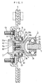
- a bearing device for an axle shown in these figures is a type of device used in a driving wheel side and comprises a hub wheel 1, a double row rolling bearing 2 and a constant velocity joint 3.
- the hub wheel 1 has a radially outward flange 11 to which a wheel not shown in a figure is mounted and a hollow shaft 12 wherein the double row rolling bearing 2 is fixed to a bearing engaging region in an outer periphery thereof.
- a raceway surface 22a for a group of balls 22 is formed closer to a vehicle outer side in an outer peripheral face of the hollow shaft 12 of the hub wheel 1.
- a shaft end in a vehicle inner side of the hollow shaft 12 of the hub wheel 1 is bent in a radially outward direction so as to constitute a caulked portion 12a, which is caulked to an outer end face of an inner ring 25 in the vehicle inner side of the double row rolling bearing 2.
- the double row rolling bearing 2 comprises a single outer ring 21 having double row raceway grooves, a plurality of balls 22 as a rolling element arranged in double rows and two crown-shaped cages 23.
- a single outer ring 21 having double row raceway grooves, a plurality of balls 22 as a rolling element arranged in double rows and two crown-shaped cages 23.
- the raceway surface 22a in the vehicle outer side of the hub wheel 1 as previously described and the configuration thereof is that only the inner ring 25 in the vehicle inner side is equipped.
- a radially outward flange 24 which is bolt-fixed to a vehicle body 6 and the like is formed on the outer ring 21.
- a well-known, what is termed Zeppa type (bar field type) of constant velocity joint is designated for the constant velocity joint 3, which comprises an outer ring 31, an inner ring 32, a ball 33 and a cage 34 and the like.
- the outer ring 31 comprises a cup-shaped cylindrical portion 35 wherein the outer ring 31, the inner ring 32, the ball 33 and the cage 34 are accommodated, and a shaft portion (an outer ring shaft portion) 36 which is arranged integral with the cup-shaped cylindrical portion 35 in a small diameter side thereof.
- An end side of a shaft (a driving shaft) 7 is fitted into the inner ring 32 by a spline fitting and fixed by a locating snap ring (symbol omitted) so as not to come off.
- Another end side of the shaft 7 is attached to a vehicle deferential device via another constant velocity joint not shown in a figure.
- the double row rolling bearing 2 is mounted in an outer peripheral face of the hub wheel 1 and the constant velocity joint 3 is mounted to the hub wheel 1 in proximity to the double row rolling bearing 2.
- a bolt 13 to fix a disk rotor 4 of a disk brake device and a wheel (not shown in a figure) is penetrably inserted into a few positions in a circumference of the flange 11.
- a rotational motive power of the shaft 7 is conveyed to the wheel which is mounted to the hub wheel 1 (not shown in a figure) via the constant velocity joint 3.
- the caulked portion 12a which is formed by bending and deforming the shaft end in the vehicle outer side of the hollow shaft 12 in a radially outward direction and the cup-shaped cylindrical portion 35 in the outer ring 31 of the constant velocity joint 3 are in a state of no contact or a slight contact with each other.
- a held portion provided between an axial intermediate position 12b of an inner periphery of the hollow shaft 12 of the hub wheel 1 and the vehicle outer side is sandwiched from an axial direction by an axial intermediate position 36b and the vehicle outer side in the outer periphery of the outer ring shaft portion 36 of the constant velocity joint 3, whereby the outer ring of the constant velocity joint 3 is joined with the hub wheel 1 in a state of being positioned in the axial direction.
- a range between the caulked portion 12a that is the shaft end in the vehicle inner side and the axial intermediate portion 12b constitutes a large diameter
- a range between the axial intermediate position 12b and the shaft end in the vehicle outer side constitutes a small diameter.
- the inner periphery has a first step obtained by the diameters, and a female spline 12c is provided on the small diameter thereof.
- a range between the shaft end 36a in the vehicle inner side and the axial intermediate portion 36b constitutes a large diameter
- a range between the axial intermediate position 36b and the vehicle outer side constitutes a small diameter.
- the outer periphery has a second step obtained by the diameters, and a male spline 36c is provided on the small diameter thereof.
- a peripheral groove 12d to latch together with a snap ring 50 is provided on the vehicle outer side of the hollow shaft 12.
- the peripheral groove 12d has opposing inner walls 12e and 12f in the vehicle inner and outer sides in the axial direction.
- the inner wall 12f in the vehicle outer side constitutes a slant face structure gradually inclining to the vehicle outer side toward a groove opening side from a groove bottom side.
- a bolt hole 36e toward the vehicle inner side is provided in the end face center of a shaft end 36d in the vehicle outer side in the outer ring shaft portion 36 of the constant velocity joint 3.
- a bolt 36f as a fastening member is screwed into the bolt hole 36e.
- an end face 36g of the shaft end 36d in the vehicle outer side of the outer ring shaft portion 36 of the constant velocity joint 3 is in a state of a substantial concordance in a radial direction with an inner wall 12e in the vehicle inner side of the peripheral groove 12d in the hollow shaft portion 12 of the hub wheel 1, and the outer ring shaft portion 36 thereof is inserted into the hollow shaft portion 12.
- the snap ring 50 is an annular member latching together with the peripheral groove 12d and extending in a radially inward direction and is compressed with a diameter thereof reduced from a length of the radial direction shown in a solid line in a free state to a length of the radial direction shown in a dashed line. Then, compression state of the snap ring 50 is released toward inside the peripheral groove 12d of the hollow shaft portion 12.
- an outer diameter side of the snap ring 50 is extended in the radial direction by a diameter expanding elastic force thereof, and inserted into the peripheral groove 12d as shown in a phantom line.
- the bolt 36f shown in a solid line is screwed into the bolt hole 36e of the outer ring shaft portion 36 via the snap ring 50 as illustrated in a phantom line, and an inner peripheral side of the snap ring 50 is sandwiched between an end face 36h inside a head portion of the bolt 36f and an end face 36g of the shaft end 36d in the vehicle outer side of the outer ring shaft portion 36.
- the snap ring 50 presses the inner wall 12f in the vehicle outer side of the peripheral groove 12d, which is subject to a diameter expanding elastic force F of the snap ring 50 from an outer peripheral angle portion thereof.
- the diameter expanding elastic force F is converted into a force to draw the outer ring shaft portion 36 to the vehicle outer side by an abutment of the peripheral groove against the inner wall in the vehicle outer side. More specifically, the diameter expanding elastic force F is divided into an axial load Fa and an axial load Fb.
- the hollow shaft portion 12 intends to be displaced to the vehicle outer side by the axial load Fa.
- the hollow shaft portion 12 is fixed to a vehicle body 6, therefore the outer ring portion 36 side is drawn to the hollow shaft portion 12 by the axial load.Fa.
- the outer ring shaft portion 36 is combined with the hollow shaft portion 12 so as to be positioned with no rattle in the axial direction.
- a large axial load in the vehicle inner side direction is occasionally imposed on the outer ring shaft portion 36. It is preferable to prevent the outer ring shaft portion 36 from coming off to the vehicle inner side direction by such an axial load.
- a gap ⁇ s between an inner diameter of the snap ring 50 and an outer diameter of the bolt 36f a gap ⁇ h (> ⁇ s) between an outer diameter of the snap ring 50 and an inner diameter of the hollow shaft portion is set to a large value.
- the outer ring shaft portion 36 is combined with the hollow shaft portion 12 with no rattle in the axial direction. Also, in this combination, the hollow shaft 12 is subject to no axial compression load, which could lead to a deformation of an inner ring raceway of the double row rolling bearing 2.
- the inner wall 12f in the vehicle outer side of the peripheral groove 12d of the hollow shaft 12 of the hub wheel 1 is configured in a slant face, and the inner wall 12e in the vehicle inner side thereof is configured in a perpendicular face, while the snap ring 50 is of an usual form.
- inner walls 12e and 12f may both constitute a perpendicular face and a snap ring 50 may be of a different form.
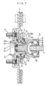
- the snap ring 50 is circumferentially corrugated in configuration and has an axial width ta (>ta, in a limited case th is an axial groove width of a peripheral groove 12d).
- the snap ring 50 is inserted into the peripheral groove 12d in a state of being elastically compressed in an axial direction. Subsequent to that, an outer ring shaft portion 36 of a constant velocity 3 is drawn to a vehicle outer side by an action of an elasticity restoring force inside the peripheral groove 12d of the snap ring 50.
- a small diameter screw-threaded shaft portion 36i is provided in the shaft end 36d in the vehicle outer side of the outer ring shaft portion 36, a nut 51 is screwed into the small diameter screw-threaded shaft portion 36i. Then, the snap ring 50 is sandwiched between an inner end face 36j of the nut 51 and an end face 36g of the shaft end 36d in the vehicle outer side of the outer ring shaft portion 36 in order for a stable location in the axial direction.
- a fine gap G exists between a caulked portion 12a which is bent and deformed in a radially outward direction in the shaft end in the vehicle outer side of a hollow shaft portion 12 of a hub wheel 1 and a cup-shaped cylindrical portion 35 of the outer ring 31 of the constant velocity joint 3.
- a risk of an entry of muddy water into the fine gap which may develop a corrosion therein caused by the muddy water remaining in a spline gap between an inner periphery of the hollow shaft portion 12 and an outer periphery of the outer ring shaft portion 36 of the constant velocity joint 3.
- seals 20 and 21 shown in Figs. 10 and 11 may be provided.
- Fig. 10 shows a side view of a longitudinal view of a bearing device for an axle
- Fig. 11 shows respective enlarged views of a main potion in Fig. 10 in order to illustrate a configuration example of the respective seals.
- the seal 20 is made of an elastic body such as a rubber and the like and arranged between opposing faces in an axial direction of a caulked portion 12a and of a cup-shaped cylindrical portion 35.
- the seal 20 is inserted into an annular groove 35a as a concave portion shown in Fig. 11A - D or a cut out 35b as a concave portion shown in Fig. 11D so as to bung up the fine gap and prevent the entry of muddy water inside thereby.
- the seal 21 is made of an elastic body such as a rubber and the like and arranged between opposing faces of an inner peripheral region of the hollow shaft 12 located closer to the vehicle inner side than splines 12f and 36f and of an outer peripheral region of the outer ring shaft portion 36 of the constant velocity joint 3.
- the seal 21 is inserted into an annular groove 36h as a concave portion shown in Fig. 11A - D so as to seal a space between the inner peripheral region of the hollow shaft portion 12 and the outer peripheral region of the outer ring shaft portion 36. This insertion prevents the entry of muddy water into the seal device 20 and the splines 12f and 36f and a subsequent corrosion therein.
- the seals 20 and 21 are not both indispensable and either of them may be used.
- the seals 20 and 21 may comprise a seal lip which is fixed to an annular cored bar having been inserted into the annular grooves 35a and 36h and the cut out 35b.
- the caulked portion 12a of the hub wheel 1 and the cup-shaped cylindrical portion 35 axially opposing thereto are referred to as being in a non-contact state.
- the present invention is not limited to the reference.
- the outer ring 31 of the constant velocity joint 3 may be combined with the hub wheel 1 in a state the caulked portion 12a and the cup-shaped cylindrical portion 35 are in contact with each other.
- the snap ring 50 as a separate body therefrom, was mentioned.
- the annular member may be integrally configured with the hollow shaft portion 12 as a part thereof.
- the present invention can be applied to a bearing device for an axle wherein a disk rotor of a disk brake device and wheels can be mounted.
Abstract
Description
Claims (8)
- A bearing device for an axle comprising:a hub wheel having a hollow shaft portion;a rolling bearing outwardly fitted to the hollow shaft portion of the hub wheel;a constant velocity joint linking tiltably a driving shaft with the hub wheel and having an outer ring; anda fastening member fastening the constant velocity joint to the hub wheel;
wherein the outer ring of the constant velocity joint has a cylindrical portion accommodating tilt movement guiding elements with respect to the driving shaft and a shaft portion (an outer ring shaft portion) formed integral with the cylindrical portion and inserted into the hollow shaft portion of the hub wheel so as not to be rotated in a circumferential direction;the fastening member is mounted to a vehicle outer side of the outer ring shaft portion of the constant velocity joint;a held portion is provided between an axial intermediate position and a vehicle outer side in the hollow shaft portion of the hub wheel;the held portion is sandwiched in an axial direction between an axial intermediate position in the outer ring shaft portion of the constant velocity joint and the fastening member, thereby the outer ring of the constant velocity joint is combined with the hub wheel in a state of being positioned in an axial direction. - A bearing device for an axle according to the claim 1, wherein:the hollow shaft portion of the hub wheel has a first step by a vehicle inner side constituting a large diameter and by a vehicle outer side constituting a small diameter in an axial intermediate position in an inner periphery thereof;the outer ring shaft portion of the constant velocity joint has a second step by an inner side constituting a large diameter and by a vehicle outer side constituting a small diameter in an axial intermediate position in an outer periphery thereof;the held portion is formed by the first step and the vehicle outer side in the hollow shaft portion of the hub wheel, and the held portion is sandwiched from an axial direction by the second step in the outer ring shaft portion of the constant velocity joint and the fastening member.
- A bearing device for an axle according to the claim 1, wherein:the hollow shaft portion of the hub wheel has a radially inward annular member in an inner periphery of the vehicle outer side thereof;the held portion is formed by the axial intermediate position in the hollow shaft portion of the hub wheel and the annular member, and the held portion is sandwiched from an axial direction by the axial intermediate position in the outer ring shaft portion of the constant velocity joint and the fastening member, thereby the outer ring of the constant velocity joint is combined with the hub wheel in a state of being positioned in an axial direction.
- A bearing device for an axle according to the claim 3, wherein:a peripheral groove is provided in the inner periphery in the vehicle outer side of the hollow shaft portion of the hub wheel, and the annular member comprises a snap ring latched together with the peripheral groove and extending in a radially inward direction;the outer ring shaft portion of the constant velocity joint is fitted to the hollow shaft portion of the hub wheel so as not to be rotated, and the snap ring is inserted into the peripheral groove of the hollow shaft portion in a state of a diameter thereof being elastically expanded and is also fixed to a shaft end in the vehicle outer side of the outer ring shaft portion in a state of being positioned in an axial direction;the peripheral groove converts a diameter expanding elastic force (first force) of the snap ring into a force (second force) to draw the outer ring shaft portion to a vehicle outer side.
- A bearing device for an axle according to the claim 4, whereinan inner wall in a vehicle outer side in the peripheral groove constitutes a slant face gradually inclining to a vehicle outer side toward a groove opening side from a groove bottom side, and wherein the first force is converted into the second force by an abutment of an outer peripheral angle portion of the snap ring against the slant face.
- A bearing device for an axle according to the claim 4, whereinthe outer ring shaft portion is fitted to the hollow shaft portion so as not to be rotated, and a circumferentially corrugated snap ring is inserted into the peripheral groove of the hollow shaft portion in a state of being elastically compressed in an axial direction and is also fixed to an end portion in the vehicle outer side of the outer ring shaft portion in a state of being positioned in an axial direction;an elasticity restoring force of the snap ring acts in a manner of drawing the outer ring shaft portion to a vehicle outer side.
- A bearing device for an axle according to the claim 4, wherein:a bolt hole is provided in an end face of the shaft end in the vehicle outer side of the outer ring shaft portion of the constant velocity joint, and the fastening member constitutes a bolt screwed into the bolt hole;a manner wherein the snap ring is fixed to the shaft end in the vehicle outer side of the outer ring shaft portion coincides with a manner wherein an inner peripheral side of the snap ring is sandwiched and fixed between the end face of the shaft end in the vehicle outer side of the outer ring shaft portion and an end face of the bolt screwed into the bolt hole.
- A bearing device for an axle according to the claim 4, wherein:a small diameter screw-threaded shaft portion is provided in the end face of the shaft end in the vehicle outer side of the outer ring shaft portion of the constant velocity joint, and the fastening member constitutes a nut screwed into the small diameter screw-threaded shaft portion;a manner wherein the snap ring is fixed to the end portion in the vehicle outer side of the outer ring shaft portion coincides with a manner wherein the inner peripheral side of the snap ring is sandwiched and fixed between an end face of the shaft end in the vehicle outer side of the outer ring shaft portion and an end face of the nut screwed into the small diameter screw-threaded shaft portion.
Applications Claiming Priority (3)
| Application Number | Priority Date | Filing Date | Title |
|---|---|---|---|
| JP2000243527 | 2000-08-11 | ||
| JP2000243527A JP4649713B2 (en) | 2000-08-11 | 2000-08-11 | Axle bearing device |
| PCT/JP2001/006949 WO2002014087A1 (en) | 2000-08-11 | 2001-08-10 | Bearing device for axle |
Publications (3)
| Publication Number | Publication Date |
|---|---|
| EP1308316A1 true EP1308316A1 (en) | 2003-05-07 |
| EP1308316A4 EP1308316A4 (en) | 2005-03-02 |
| EP1308316B1 EP1308316B1 (en) | 2007-07-18 |
Family
ID=18734364
Family Applications (1)
| Application Number | Title | Priority Date | Filing Date |
|---|---|---|---|
| EP01956850A Expired - Lifetime EP1308316B1 (en) | 2000-08-11 | 2001-08-10 | Bearing device for axle |
Country Status (5)
| Country | Link |
|---|---|
| US (1) | US6851865B2 (en) |
| EP (1) | EP1308316B1 (en) |
| JP (1) | JP4649713B2 (en) |
| DE (1) | DE60129443T2 (en) |
| WO (1) | WO2002014087A1 (en) |
Cited By (5)
| Publication number | Priority date | Publication date | Assignee | Title |
|---|---|---|---|---|
| EP1314905A1 (en) * | 2000-08-31 | 2003-05-28 | Koyo Seiko Co., Ltd. | Bearing device for vehicle |
| EP1201459A3 (en) * | 2000-10-25 | 2003-12-03 | Koyo Seiko Co., Ltd. | Bearing apparatus for vehicle |
| EP1477328A3 (en) * | 2003-05-14 | 2006-11-02 | MAN Nutzfahrzeuge Aktiengesellschaft | Bearing device for a steerable vehicle wheel |
| DE102006042533A1 (en) * | 2006-09-11 | 2008-03-27 | Gkn Driveline Deutschland Gmbh | Wheel hub-swivel joint-arrangement, has tensioning unit with central pulling unit between wheel hub and drive journal, and safety ring inserted into nut in passage opening, where annular disk supports pulling unit that pulls drive journal |
| CN102458879A (en) * | 2009-06-03 | 2012-05-16 | Ntn株式会社 | Bearing device for wheel |
Families Citing this family (14)
| Publication number | Priority date | Publication date | Assignee | Title |
|---|---|---|---|---|
| JP4474774B2 (en) * | 2000-05-31 | 2010-06-09 | 日本精工株式会社 | Wheel drive unit |
| US6626579B1 (en) * | 2002-01-31 | 2003-09-30 | Kelsey-Hayes Company | Anti-corrosion member for use in a vehicle wheel end assembly having an aluminum steering knuckle |
| US7121632B2 (en) * | 2004-05-05 | 2006-10-17 | Gkn Driveline North Amercia, Inc. | Shaft and wheel hub retention assembly |
| JP4940566B2 (en) * | 2005-03-30 | 2012-05-30 | 株式会社ジェイテクト | Wheel bearing device |
| DE102005018126A1 (en) * | 2005-04-20 | 2006-10-26 | Schaeffler Kg | Wheel bearing joint unit |
| DE102006030478A1 (en) * | 2006-07-01 | 2008-01-03 | Schaeffler Kg | Bearing structure for a motor vehicle's wheel hub (WH) driven by a turning knuckle (TK) uses gearing to form a torque- proof link between the WH and the TK linked to a wheel flange and a drive shaft |
| DE102006034038B4 (en) * | 2006-07-24 | 2008-08-14 | Gkn Driveline Deutschland Gmbh | Hub-swivel assembly with locking ring for axial support of the tension |
| EP2127902B1 (en) * | 2007-03-07 | 2019-01-16 | NTN Corporation | Bearing device for driving wheel, and its assembling method |
| US8801294B2 (en) * | 2007-09-18 | 2014-08-12 | Ntn Corporation | Bearing device for a wheel |
| EP2112002A3 (en) * | 2008-03-28 | 2009-12-09 | JTEKT Corporation | Wheel bearing assembly and manufacturing method thereof |
| JP5679742B2 (en) * | 2010-09-09 | 2015-03-04 | Dmg森精機株式会社 | Bearing preload structure for machine tools |
| US8616779B2 (en) | 2010-11-29 | 2013-12-31 | Honda Motor Co., Ltd. | Shortened driveshaft stem |
| DE102011086106A1 (en) * | 2011-11-10 | 2013-05-16 | Zf Friedrichshafen Ag | Connection assembly for axially connecting e.g. drive and shaft in construction machine gearbox, has securing device comprising connecting part engaged in recess in first component and fixedly connected at front end of second component |
| KR101416384B1 (en) | 2012-12-14 | 2014-07-08 | 기아자동차 주식회사 | Wheel bearing unit for vehicle |
Citations (1)
| Publication number | Priority date | Publication date | Assignee | Title |
|---|---|---|---|---|
| US2595787A (en) * | 1947-03-12 | 1952-05-06 | Waldes Kohinoor Inc | Retaining ring assembly |
Family Cites Families (10)
| Publication number | Priority date | Publication date | Assignee | Title |
|---|---|---|---|---|
| JP3871455B2 (en) | 1998-12-22 | 2007-01-24 | Ntn株式会社 | Constant velocity joint |
| US4371214A (en) | 1980-11-17 | 1983-02-01 | Motor Wheel Corporation | Bearing hub and carrier assembly for a driven steering wheel unit |
| DE3430067C1 (en) | 1984-08-16 | 1989-04-06 | Löhr & Bromkamp GmbH, 6050 Offenbach | PTO shaft |
| JPH0656088B2 (en) | 1986-10-28 | 1994-07-27 | 富士バルブ株式会社 | Lightweight engine valve and manufacturing method thereof |
| JPH0621529B2 (en) | 1986-10-28 | 1994-03-23 | 富士バルブ株式会社 | Lightweight engine valve manufacturing method |
| JPS63109204U (en) * | 1987-01-09 | 1988-07-14 | ||
| JPS63109203U (en) * | 1987-01-09 | 1988-07-14 | ||
| JP3982093B2 (en) * | 1998-02-16 | 2007-09-26 | 日本精工株式会社 | Wheel drive axle unit |
| US6485188B1 (en) * | 2000-04-21 | 2002-11-26 | The Timken Company | Wheel mounting with a bearing race embedded in a cast component |
| JP3869202B2 (en) * | 2000-10-25 | 2007-01-17 | 株式会社ジェイテクト | Hub unit for vehicles |
-
2000
- 2000-08-11 JP JP2000243527A patent/JP4649713B2/en not_active Expired - Fee Related
-
2001
- 2001-08-10 EP EP01956850A patent/EP1308316B1/en not_active Expired - Lifetime
- 2001-08-10 DE DE60129443T patent/DE60129443T2/en not_active Expired - Lifetime
- 2001-08-10 US US10/240,408 patent/US6851865B2/en not_active Expired - Fee Related
- 2001-08-10 WO PCT/JP2001/006949 patent/WO2002014087A1/en active IP Right Grant
Patent Citations (1)
| Publication number | Priority date | Publication date | Assignee | Title |
|---|---|---|---|---|
| US2595787A (en) * | 1947-03-12 | 1952-05-06 | Waldes Kohinoor Inc | Retaining ring assembly |
Non-Patent Citations (1)
| Title |
|---|
| See also references of WO0214087A1 * |
Cited By (8)
| Publication number | Priority date | Publication date | Assignee | Title |
|---|---|---|---|---|
| EP1314905A1 (en) * | 2000-08-31 | 2003-05-28 | Koyo Seiko Co., Ltd. | Bearing device for vehicle |
| EP1314905A4 (en) * | 2000-08-31 | 2006-01-18 | Koyo Seiko Co | Bearing device for vehicle |
| EP1201459A3 (en) * | 2000-10-25 | 2003-12-03 | Koyo Seiko Co., Ltd. | Bearing apparatus for vehicle |
| EP1477328A3 (en) * | 2003-05-14 | 2006-11-02 | MAN Nutzfahrzeuge Aktiengesellschaft | Bearing device for a steerable vehicle wheel |
| DE102006042533A1 (en) * | 2006-09-11 | 2008-03-27 | Gkn Driveline Deutschland Gmbh | Wheel hub-swivel joint-arrangement, has tensioning unit with central pulling unit between wheel hub and drive journal, and safety ring inserted into nut in passage opening, where annular disk supports pulling unit that pulls drive journal |
| DE102006042533B4 (en) * | 2006-09-11 | 2009-09-24 | Gkn Driveline Deutschland Gmbh | Wheel hub / swivel assembly with backlash-free axial locking of the wheel hub |
| CN102458879A (en) * | 2009-06-03 | 2012-05-16 | Ntn株式会社 | Bearing device for wheel |
| CN102458879B (en) * | 2009-06-03 | 2014-06-11 | Ntn株式会社 | Bearing device for wheel |
Also Published As
| Publication number | Publication date |
|---|---|
| JP2002052901A (en) | 2002-02-19 |
| EP1308316A4 (en) | 2005-03-02 |
| EP1308316B1 (en) | 2007-07-18 |
| DE60129443T2 (en) | 2008-04-03 |
| US20030048966A1 (en) | 2003-03-13 |
| WO2002014087A1 (en) | 2002-02-21 |
| US6851865B2 (en) | 2005-02-08 |
| DE60129443D1 (en) | 2007-08-30 |
| JP4649713B2 (en) | 2011-03-16 |
Similar Documents
| Publication | Publication Date | Title |
|---|---|---|
| EP1308316B1 (en) | Bearing device for axle | |
| US6705763B2 (en) | Mounting structure for rolling bearing | |
| US7866893B2 (en) | Bearing apparatus for a wheel of vehicle | |
| US7175349B2 (en) | Wheel rotation supporting apparatus | |
| EP1715202B9 (en) | Bearing apparatus for a driving wheel of vehicle | |
| US6550975B2 (en) | Bearing apparatus for vehicle | |
| US6974259B2 (en) | Bearing device for vehicle | |
| JP5401997B2 (en) | Hub unit for driving wheel support | |
| US8142081B2 (en) | Wheel support bearing assembly | |
| JP2005212713A (en) | Bearing device for wheel | |
| JP4042528B2 (en) | Rolling bearing device | |
| JP2002339959A (en) | Manufacturing method for rolling bearing unit for drive wheel, and drive unit for wheel | |
| JP2000229501A (en) | Wheel supporting hub unit | |
| JP2005127450A (en) | Hub unit bearing for supporting wheel | |
| JP2002087011A (en) | Bearing device for vehicle | |
| JP2008222098A (en) | Semi-floating type axle supporting device | |
| JP2010133482A (en) | Roller bearing device | |
| JP2005255165A (en) | Driving wheel roller bearing unit and wheel driving unit manufacturing method | |
| JP2005219650A (en) | Bearing device for driving wheel | |
| JP2009079630A (en) | Wheel support device | |
| KR101484142B1 (en) | Wheel bearing for vehicle | |
| JP2003120700A (en) | Wheel rotation support device and its assembly method | |
| JP2007022237A (en) | Bearing device for driving wheel | |
| JP2012201225A (en) | Rolling bearing unit for drive wheel | |
| JP2003042174A (en) | Mounting structure of rolling bearing roller |
Legal Events
| Date | Code | Title | Description |
|---|---|---|---|
| PUAI | Public reference made under article 153(3) epc to a published international application that has entered the european phase |
Free format text: ORIGINAL CODE: 0009012 |
|
| 17P | Request for examination filed |
Effective date: 20021012 |
|
| AK | Designated contracting states |
Designated state(s): AT BE CH CY DE DK ES FI FR GB GR IE IT LI LU MC NL PT SE TR |
|
| RBV | Designated contracting states (corrected) |
Designated state(s): DE FR GB IT |
|
| A4 | Supplementary search report drawn up and despatched |
Effective date: 20050119 |
|
| RIC1 | Information provided on ipc code assigned before grant |
Ipc: 7B 60B 35/14 A Ipc: 7B 60B 27/00 B Ipc: 7F 16D 3/20 B |
|
| RAP1 | Party data changed (applicant data changed or rights of an application transferred) |
Owner name: JTEKT CORPORATION |
|
| GRAP | Despatch of communication of intention to grant a patent |
Free format text: ORIGINAL CODE: EPIDOSNIGR1 |
|
| GRAS | Grant fee paid |
Free format text: ORIGINAL CODE: EPIDOSNIGR3 |
|
| GRAA | (expected) grant |
Free format text: ORIGINAL CODE: 0009210 |
|
| AK | Designated contracting states |
Kind code of ref document: B1 Designated state(s): DE FR GB IT |
|
| REG | Reference to a national code |
Ref country code: GB Ref legal event code: FG4D |
|
| REF | Corresponds to: |
Ref document number: 60129443 Country of ref document: DE Date of ref document: 20070830 Kind code of ref document: P |
|
| ET | Fr: translation filed | ||
| PGFP | Annual fee paid to national office [announced via postgrant information from national office to epo] |
Ref country code: GB Payment date: 20070810 Year of fee payment: 7 |
|
| PGFP | Annual fee paid to national office [announced via postgrant information from national office to epo] |
Ref country code: IT Payment date: 20070727 Year of fee payment: 7 |
|
| PLBE | No opposition filed within time limit |
Free format text: ORIGINAL CODE: 0009261 |
|
| STAA | Information on the status of an ep patent application or granted ep patent |
Free format text: STATUS: NO OPPOSITION FILED WITHIN TIME LIMIT |
|
| 26N | No opposition filed |
Effective date: 20080421 |
|
| GBPC | Gb: european patent ceased through non-payment of renewal fee |
Effective date: 20080810 |
|
| PG25 | Lapsed in a contracting state [announced via postgrant information from national office to epo] |
Ref country code: IT Free format text: LAPSE BECAUSE OF NON-PAYMENT OF DUE FEES Effective date: 20080810 |
|
| PG25 | Lapsed in a contracting state [announced via postgrant information from national office to epo] |
Ref country code: GB Free format text: LAPSE BECAUSE OF NON-PAYMENT OF DUE FEES Effective date: 20080810 |
|
| PGFP | Annual fee paid to national office [announced via postgrant information from national office to epo] |
Ref country code: DE Payment date: 20120808 Year of fee payment: 12 Ref country code: FR Payment date: 20120823 Year of fee payment: 12 |
|
| PG25 | Lapsed in a contracting state [announced via postgrant information from national office to epo] |
Ref country code: DE Free format text: LAPSE BECAUSE OF NON-PAYMENT OF DUE FEES Effective date: 20140301 |
|
| REG | Reference to a national code |
Ref country code: DE Ref legal event code: R119 Ref document number: 60129443 Country of ref document: DE Effective date: 20140301 |
|
| REG | Reference to a national code |
Ref country code: FR Ref legal event code: ST Effective date: 20140430 |
|
| PG25 | Lapsed in a contracting state [announced via postgrant information from national office to epo] |
Ref country code: FR Free format text: LAPSE BECAUSE OF NON-PAYMENT OF DUE FEES Effective date: 20130902 |