EP1308279A2 - Image correction method in inkjet recording apparatus - Google Patents
Image correction method in inkjet recording apparatus Download PDFInfo
- Publication number
- EP1308279A2 EP1308279A2 EP02024683A EP02024683A EP1308279A2 EP 1308279 A2 EP1308279 A2 EP 1308279A2 EP 02024683 A EP02024683 A EP 02024683A EP 02024683 A EP02024683 A EP 02024683A EP 1308279 A2 EP1308279 A2 EP 1308279A2
- Authority
- EP
- European Patent Office
- Prior art keywords
- nozzle
- nonejecting
- color
- different
- nozzles
- Prior art date
- Legal status (The legal status is an assumption and is not a legal conclusion. Google has not performed a legal analysis and makes no representation as to the accuracy of the status listed.)
- Granted
Links
- 238000000034 method Methods 0.000 title claims abstract description 37
- 238000003702 image correction Methods 0.000 title claims description 12
- 230000000295 complement effect Effects 0.000 claims abstract description 75
- 238000009826 distribution Methods 0.000 claims abstract description 66
- 238000004364 calculation method Methods 0.000 claims description 22
- 230000010354 integration Effects 0.000 claims description 10
- 230000000007 visual effect Effects 0.000 claims description 7
- 230000003287 optical effect Effects 0.000 claims description 5
- 238000012546 transfer Methods 0.000 claims description 3
- 230000015556 catabolic process Effects 0.000 abstract description 2
- 238000006731 degradation reaction Methods 0.000 abstract description 2
- 230000000875 corresponding effect Effects 0.000 description 35
- 239000000976 ink Substances 0.000 description 31
- 238000012545 processing Methods 0.000 description 15
- 238000003705 background correction Methods 0.000 description 11
- 238000012937 correction Methods 0.000 description 9
- 238000013500 data storage Methods 0.000 description 9
- 238000001514 detection method Methods 0.000 description 8
- 238000006243 chemical reaction Methods 0.000 description 6
- 230000002596 correlated effect Effects 0.000 description 6
- 230000000694 effects Effects 0.000 description 5
- 238000012935 Averaging Methods 0.000 description 3
- 230000007547 defect Effects 0.000 description 3
- 238000010586 diagram Methods 0.000 description 3
- 239000006185 dispersion Substances 0.000 description 3
- 239000003086 colorant Substances 0.000 description 2
- 238000004891 communication Methods 0.000 description 2
- 238000009792 diffusion process Methods 0.000 description 2
- 230000010365 information processing Effects 0.000 description 2
- 239000003550 marker Substances 0.000 description 2
- 238000012986 modification Methods 0.000 description 2
- 230000004048 modification Effects 0.000 description 2
- 239000000654 additive Substances 0.000 description 1
- 230000003466 anti-cipated effect Effects 0.000 description 1
- 238000007796 conventional method Methods 0.000 description 1
- 230000003247 decreasing effect Effects 0.000 description 1
- 238000005516 engineering process Methods 0.000 description 1
- 238000004519 manufacturing process Methods 0.000 description 1
- 238000010606 normalization Methods 0.000 description 1
- 230000000704 physical effect Effects 0.000 description 1
- 238000007639 printing Methods 0.000 description 1
Images


Classifications
-
- B—PERFORMING OPERATIONS; TRANSPORTING
- B41—PRINTING; LINING MACHINES; TYPEWRITERS; STAMPS
- B41J—TYPEWRITERS; SELECTIVE PRINTING MECHANISMS, i.e. MECHANISMS PRINTING OTHERWISE THAN FROM A FORME; CORRECTION OF TYPOGRAPHICAL ERRORS
- B41J2/00—Typewriters or selective printing mechanisms characterised by the printing or marking process for which they are designed
- B41J2/005—Typewriters or selective printing mechanisms characterised by the printing or marking process for which they are designed characterised by bringing liquid or particles selectively into contact with a printing material
- B41J2/01—Ink jet
- B41J2/015—Ink jet characterised by the jet generation process
- B41J2/04—Ink jet characterised by the jet generation process generating single droplets or particles on demand
- B41J2/045—Ink jet characterised by the jet generation process generating single droplets or particles on demand by pressure, e.g. electromechanical transducers
- B41J2/04501—Control methods or devices therefor, e.g. driver circuits, control circuits
- B41J2/0451—Control methods or devices therefor, e.g. driver circuits, control circuits for detecting failure, e.g. clogging, malfunctioning actuator
-
- B—PERFORMING OPERATIONS; TRANSPORTING
- B41—PRINTING; LINING MACHINES; TYPEWRITERS; STAMPS
- B41J—TYPEWRITERS; SELECTIVE PRINTING MECHANISMS, i.e. MECHANISMS PRINTING OTHERWISE THAN FROM A FORME; CORRECTION OF TYPOGRAPHICAL ERRORS
- B41J2/00—Typewriters or selective printing mechanisms characterised by the printing or marking process for which they are designed
- B41J2/005—Typewriters or selective printing mechanisms characterised by the printing or marking process for which they are designed characterised by bringing liquid or particles selectively into contact with a printing material
- B41J2/01—Ink jet
- B41J2/015—Ink jet characterised by the jet generation process
- B41J2/04—Ink jet characterised by the jet generation process generating single droplets or particles on demand
- B41J2/045—Ink jet characterised by the jet generation process generating single droplets or particles on demand by pressure, e.g. electromechanical transducers
- B41J2/04501—Control methods or devices therefor, e.g. driver circuits, control circuits
- B41J2/04558—Control methods or devices therefor, e.g. driver circuits, control circuits detecting presence or properties of a dot on paper
-
- B—PERFORMING OPERATIONS; TRANSPORTING
- B41—PRINTING; LINING MACHINES; TYPEWRITERS; STAMPS
- B41J—TYPEWRITERS; SELECTIVE PRINTING MECHANISMS, i.e. MECHANISMS PRINTING OTHERWISE THAN FROM A FORME; CORRECTION OF TYPOGRAPHICAL ERRORS
- B41J2/00—Typewriters or selective printing mechanisms characterised by the printing or marking process for which they are designed
- B41J2/005—Typewriters or selective printing mechanisms characterised by the printing or marking process for which they are designed characterised by bringing liquid or particles selectively into contact with a printing material
- B41J2/01—Ink jet
- B41J2/015—Ink jet characterised by the jet generation process
- B41J2/04—Ink jet characterised by the jet generation process generating single droplets or particles on demand
- B41J2/045—Ink jet characterised by the jet generation process generating single droplets or particles on demand by pressure, e.g. electromechanical transducers
- B41J2/04501—Control methods or devices therefor, e.g. driver circuits, control circuits
- B41J2/0458—Control methods or devices therefor, e.g. driver circuits, control circuits controlling heads based on heating elements forming bubbles
-
- B—PERFORMING OPERATIONS; TRANSPORTING
- B41—PRINTING; LINING MACHINES; TYPEWRITERS; STAMPS
- B41J—TYPEWRITERS; SELECTIVE PRINTING MECHANISMS, i.e. MECHANISMS PRINTING OTHERWISE THAN FROM A FORME; CORRECTION OF TYPOGRAPHICAL ERRORS
- B41J2/00—Typewriters or selective printing mechanisms characterised by the printing or marking process for which they are designed
- B41J2/005—Typewriters or selective printing mechanisms characterised by the printing or marking process for which they are designed characterised by bringing liquid or particles selectively into contact with a printing material
- B41J2/01—Ink jet
- B41J2/135—Nozzles
- B41J2/165—Preventing or detecting of nozzle clogging, e.g. cleaning, capping or moistening for nozzles
- B41J2/16579—Detection means therefor, e.g. for nozzle clogging
-
- B—PERFORMING OPERATIONS; TRANSPORTING
- B41—PRINTING; LINING MACHINES; TYPEWRITERS; STAMPS
- B41J—TYPEWRITERS; SELECTIVE PRINTING MECHANISMS, i.e. MECHANISMS PRINTING OTHERWISE THAN FROM A FORME; CORRECTION OF TYPOGRAPHICAL ERRORS
- B41J2/00—Typewriters or selective printing mechanisms characterised by the printing or marking process for which they are designed
- B41J2/005—Typewriters or selective printing mechanisms characterised by the printing or marking process for which they are designed characterised by bringing liquid or particles selectively into contact with a printing material
- B41J2/01—Ink jet
- B41J2/21—Ink jet for multi-colour printing
- B41J2/2132—Print quality control characterised by dot disposition, e.g. for reducing white stripes or banding
- B41J2/2146—Print quality control characterised by dot disposition, e.g. for reducing white stripes or banding for line print heads
-
- B—PERFORMING OPERATIONS; TRANSPORTING
- B41—PRINTING; LINING MACHINES; TYPEWRITERS; STAMPS
- B41J—TYPEWRITERS; SELECTIVE PRINTING MECHANISMS, i.e. MECHANISMS PRINTING OTHERWISE THAN FROM A FORME; CORRECTION OF TYPOGRAPHICAL ERRORS
- B41J29/00—Details of, or accessories for, typewriters or selective printing mechanisms not otherwise provided for
- B41J29/38—Drives, motors, controls or automatic cut-off devices for the entire printing mechanism
- B41J29/393—Devices for controlling or analysing the entire machine ; Controlling or analysing mechanical parameters involving printing of test patterns
Definitions
- the present invention relates to an image correction method for correcting a nonejection state, which is an inherent characteristic of each recording head of an inkjet recording system that ejects ink dots onto a recording medium to form an image thereon.
- a plural-recording-elements integrated recording head (also referred to as a multi-head) is used, in which plural ink nozzles and ink paths are integrated in high density. Furthermore, for colorization, the apparatus generally has plural multi-heads corresponding to respective colors of cyan, magenta, yellow, and black.
- a one-pass high-speed method in which the length of the multi-head is about the width of a recording medium, is coming into use.
- the length of the multi-head is about 30 cm, and 7000 nozzles or more are required to achieve 600 dpi images. It is extremely difficult to manufacture such multi-heads having such a large number of nozzles without some defects. In addition, the nozzles will not necessarily have the same performance characteristics. Furthermore, some nozzles become incapable of ejection after being used. Therefore, it is worth noting head shading techniques for correcting density nonuniformity due to ejection-amount nonuniformity and deviations in landing position (kink), as well as nonejecting-nozzle correction (nonejection complementary) techniques for performing complementary processing on a nonejecting nozzle to enable even a multi-head with defects to be used.
- head shading techniques for correcting density nonuniformity due to ejection-amount nonuniformity and deviations in landing position (kink), as well as nonejecting-nozzle correction (nonejection complementary) techniques for performing complementary processing on a nonejecting nozzle to enable even a multi-head with defects to be used.
- the density is measured for every nozzle and the input-image data is then corrected for the measured result. For example, if the ejection amount of one nozzle is reduced for some reason so as to reduce the density corresponding to that nozzle, this technique corrects the input image data so that a gradation value corresponding to the affected nozzle is increased so as to yield uniform density throughout the printed images.
- the nonejection complementary technique sets forth other methods for collecting nozzle output variations. If one nozzle for cyan is nonejecting, for example, methods for compensating for this ink shortage include (i) substituting with the ejection of nozzles on both sides of the nonejecting nozzle (adjacent complementation), (ii) complementing the nonejecting nozzle with an ink dot of another color, such as black, (different-color complementing), and (iii) distributing the data corresponding to the nonejecting nozzle to nozzles at both ends of the head.
- the different color complemented result often may vary from that anticipated, depending on the ejection condition of the adjacent nozzles.
- the amount of the ink ejected from the adjacent nozzles on both sides is large so as to increase the size of an ink dot
- the amount of different-color complementing ink is not reduced from the determined standard amount (hereinafter the amount of the complementing is referred to as a "reference different-color complementing amount")
- the resultant complementing may become conspicuous due to the effect of the large number of ink dots adjacent to the nonejecting nozzle. That is, it is necessary to determine the amount of the different-color complementing by measuring the degree of the effect on the vicinity. This situation is shown in Fig. 1.
- Solid lines in Fig. 1 show density changes when a zigzag pattern having a duty factor of 50% (a checker pattern, in which dots are recorded at a percentage of 50%) is formed with ink dots of about 60 ⁇ m at a resolution of 600 dpi.
- symbols (A1) to (A3) show the case that the dot diameter from the nozzles on both sides of the nonejecting nozzle is the same as that from other nozzles, and the number of successive nonejecting nozzles for each case is 1, 2, and 3, respectively.
- Symbols (B) and (D) show cases where the dot diameter from the nozzles on both sides are smaller by 4 ⁇ m and 7 ⁇ m, respectively.
- symbols (A1) to (A3) show cases where there is no landing-position shift (Y kink) in the nozzles on both sides of the nonejecting nozzle.
- symbols (B) and (D) show cases where the landing position of the nozzles on both sides are shifted by 7 ⁇ m and 14 ⁇ m in the direction opposite to the nonejecting nozzle, respectively.
- symbols (C) and (E) show cases where the landing position of the nozzles on both sides are shifted by 7 ⁇ m and 14 ⁇ m, in the direction toward the nonejecting nozzle, respectively. Similar to the above-mentioned case, in which the dot diameter is different, the density in the nonejecting nozzle changes depending on conditions of the nozzles on both sides.
- the standard different-color complementary amount can substantially have the same advantages.
- the ejecting conditions of nozzles in the vicinity of the nonejecting nozzle can be comprehended, and then, if there are no fluctuations in the dot density and dot diameter, the complementing may be performed with the reference different-color complementing amount. However, if there are fluctuations in the dot density and dot diameter, the complementing must be performed with an amount increased or decreased from the reference different-color complementing amount by referring to the density of the nonejecting nozzle portion.
- the present invention can provide an image correction method for correcting a nonejecting nozzle without using a high-efficiency scanner.
- a pattern for reading an ejecting state of a head is recorded and analyzed so as to determine the presence of a nonejecting nozzle while density distribution data corresponding to each nozzle is obtained so as to determine a complementary table for each nozzle so as to perform different-color complementing with reference to the density distribution in the nonejecting nozzle.
- a suitable arithmetic calculation is performed on the density distribution data corresponding to each nozzle so as to determine a complementary table for each nozzle to perform the different-color complementing.
- a complementary table is set so that the different-color complementary amount is larger than the value shown in the reference different-color complementary table.
- a complementary table is set so that the different-color complementary amount is smaller than the value shown in the reference different-color complementary table.
- an image correction method for an inkjet recording apparatus for recording images by ejecting ink on a recording medium using a recording head having a plurality of nozzles for ejecting ink arranged on the recording head includes the steps of outputting a pattern for measuring recording characteristics of the recording head, determining a nonejecting nozzle from the plurality of nozzles and obtaining a density distribution corresponding to each nozzle based on the measured density of the output pattern, determining a complementary table for each nozzle for complementing with a color different from the color corresponding to the nonejecting nozzle by comparing the obtained density distribution corresponding to the nonejecting nozzle with a reference preset value and converting image data corresponding to the nonejecting nozzle into different-color image data for ejection by another nozzle using determined complementary table.
- the reference preset value is a value of the density distribution corresponding to the nonejecting nozzle in a state that sizes and density of ink drops ejected from nozzles in the vicinity of the nonejecting nozzle are constant and there is no deviation in a landing position.
- One of a table and a function showing a complementary amount with the different color in the state for each gradation value of input images is prepared for each number of consecutive nonejecting nozzles as a reference different-color complementary table.
- a different-color complementary table for each nozzle is determined by referring to the reference different-color complementary table for each number of consecutive nonejecting nozzles.
- an image correction method for an inkjet recording apparatus for recording images by ejecting ink on a recording medium using a recording head having a plurality of nozzles for ejecting ink arranged on the recording head includes the steps of outputting a pattern for measuring recording characteristics of the recording head, determining a nonejecting nozzle from the plurality of nozzles and obtaining a density distribution corresponding to each nozzle based on the measured density of the output pattern, performing a predetermined arithmetic calculation on the obtained density distribution, determining a complementary table for each nozzle for complementing with a color different from the color corresponding to the nonejecting nozzle by comparing the calculated density distribution corresponding to the nonejecting nozzle with a reference preset value and converting image data corresponding to the nonejecting nozzle into different-color image data for ejection by another nozzle using the determined complementary table.
- the reference preset value is a value of the density distribution corresponding to the nonejecting nozzle in a state that sizes and density of ink drops ejected from nozzles in the vicinity of the nonejecting nozzle are constant and there is no deviation in a landing position.
- One of a table and a function showing a complementary amount with the different color in the state for each gradation value of input images is prepared for each number of consecutive nonejecting nozzles as a reference different-color complementary table. From a magnitude relation between density distribution corresponding to a target nonejecting nozzle and the reference preset value for each number of consecutive nonejecting nozzles, a different-color complementary table for each nozzle is determined by referring to the reference different-color complementary table for each number of consecutive nonejecting nozzles.
- Fig. 1 is a graph showing density distribution when there are fluctuations in the ejection amount in the vicinity of a nonejecting nozzle.
- Fig. 2 is a graph showing density distribution when there are fluctuations in kink in the vicinity of a nonejecting nozzle.
- Fig. 3 is a graph showing frequency response characteristics of a visual transfer function (VTF) and a point spread function (PSF).
- VTF visual transfer function
- PSF point spread function
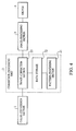
- Fig. 4 is a block flow diagram showing data processing according to an embodiment of the present invention.
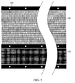
- Fig. 5 is a schematic diagram for illustrating detection of a nonejecting nozzle and a shading pattern.
- Fig. 6 is a graph showing cyan density distribution and the distribution after an arithmetic calculation according to a first embodiment.
- Fig. 7 is a graph showing complementary tables for complementing a nonejecting nozzle corresponding to cyan ink with black ink.
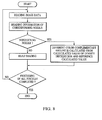
- Fig. 8 is a flow chart showing correction processing according to the first embodiment.
- Fig. 9 is a table showing density distribution for each nozzle (before and after processing) and shading data according to a second embodiment.
- Fig. 10 is a graph showing cyan density distribution, the distribution after an arithmetic calculation, and shading data according to the first embodiment.
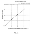
- Fig. 11 is a graph showing the relationship between the number of successive nonejecting nozzles for cyan and the reference set value.
- a pattern for reading an ejecting state of a head is recorded and measured so as to determine the presence of a nonejecting nozzle, while density distribution, corresponding to each nozzle, is obtained so as to determine a complementary table for each nozzle so as to perform different-color complementing for the nonejecting nozzle.
- Such different-color complementing may preferably include inks of different color as well as inks of similar color, but different density.
- a suitable arithmetic calculation is performed on the density distribution corresponding to each nozzle so as to determine a complementary table for each nozzle to perform the different-color complementing.
- a complementary table is set so that the different-color complementary amount is larger than the value shown in the reference different-color complementary table.
- a complementary table is set so that the different-color complementary amount is smaller than the value shown in the reference different-color complementary table.
- reference set values for each of 1, 2, and 3 successive nonejecting nozzles are compared with density distribution of a target nozzle, or a calculated value thereof, so as to obtain a relative number of successive nonejecting nozzles from the results, so that a complementary table for the relative number of successive nonejecting nozzles is prepared by referring to the reference different-color complementary tables for 1, 2, or 3 successive nonejecting nozzles, with suitable interpolation.
- the interpolation is not specifically limited, so that generally used methods such as linear interpolation or spline-curve interpolation may be used.
- the above-mentioned arithmetic calculation is to calculate the density distribution corresponding to each nozzle in units of several pixels or in consideration of visual characteristics, specifically, there are averaging processing and weighted averaging processing in units of 2 to 7 pixels on 50 ⁇ m to 300 ⁇ m and 600 dpi basis. More preferable calculations include convolution integration using a VTF (visual transfer function) representing visual characteristics and convolution integration using a PSF (point spread function). These latter methods are more preferred because the visual characteristics are reflected therein.
- VTF visual transfer function
- PSF point spread function
- the above-mentioned convolution integration is interchangeable with the inverse Fourier transformed value of the product of the Fourier transformed density distribution and the Fourier transformed VTF or PSF, so that any one of the methods may be used.
- the VTF and PSF are given by the following equations.
- the dispersion ⁇ in the PSF indicates the degree of broadening in the Gaussian function.
- a vl of 200 to 400 mm substantially corresponds to a ⁇ of 0.085 to 0.19 mm (2 to 4.5 pixels on 600 dpi basis), so that when the PSF is used, values within the above-mentioned range may be preferable.
- frequency response characteristics of the VTF and PSF are shown in Fig. 3 for reference.
- the solid lines of Figs. 1 and 2 indicate the above-mentioned density distributions when the dot diameter and Y kink are changed, respectively.
- These graphs demonstrate that the density distribution in the nonejecting nozzle is changed corresponding to ejecting conditions on both sides of the nonejecting nozzle. This results from the effect on a nonejection region of ink dots ejected from nozzles in the vicinity of the nonejecting nozzle.
- the different-color complementary table is determined by comparing a reference pre-set value with the density distribution observed for the nonejecting nozzle.
- Figs. 1 and 2 show the arithmetically processed results on the density distributions, wherein the convolution integration is performed using the VTF formula when the distance of distinct vision (vl) is 300 mm.
- the dot diameter is changed in the nozzles on both sides of the nonejecting nozzle (examples in Fig. 1)
- the result of the operation in the nonejecting nozzle is also changed; however, when only the kink is changed in the nozzles on both sides of the nonejecting nozzle (examples in Fig. 2), the result of the operation in the nonejecting nozzle is scarcely changed. Therefore, by determining the complementary amount for different-color complementing on the basis of the calculation enables the complementing to suitably account for the effect of the kink.
- the above-mentioned reference set value indicates the density distribution in the nonejecting nozzle, or the result of the operation thereof, when the density and size of the dot recorded by the nozzles in the vicinity of the nonejecting nozzle are constant and, moreover, when there is no deviation in the landing position (kink).
- This situation corresponds to results (A1) through (A3) in Figs. 1 and 2.
- the reference different-color complementary table represents the actual different-color amount to be complemented.
- the reference different-color complementary table is given as a separate table for each of a number of successive nonejecting nozzles, using the image density data in the region (gradation value) as a parameter, wherein if the result of the operation of the region corresponding to the nonejecting nozzle is larger than the reference set value regardless the number of successive nonejecting nozzles is 1 (corresponding to B and D in Fig. 1), for example, a complementary table for the nozzle is determined by referring to the reference different-color complementary tables for numbers 1 and 2 of successive nonejecting nozzles with interpolation performed therebetween.
- the interpolation is not specifically limited, so that the linear interpolation or nonlinear interpolation may be appropriately selected.
- same-color complementing may be performed using an adjacent nozzle, so that more efficient complementing can be performed.
- the reference different-color complementary table needs to be reset as a different-color complementary table after the adjacent complementing is performed with the same color.
- the information for each nozzle obtained by the arithmetic calculation may be used as a correction parameter for correcting density nonuniformity (shading correction); if higher spatial-frequency response is desired, a parameter for shading correction may also be calculated by performing a separate arithmetic calculation.
- the pattern used for checking ejection conditions of the head is a pattern such as a nonejection-detection pattern, in which lines recorded by one nozzle are step-wise arranged, and a staggered pattern with a recording duty factor of 50%; however, it is not limited to these patterns, and may be any pattern as long as nonejection of a nozzle and density distribution for each nozzle can be checked. Also, patterns with several kinds of recording duty factors may be used so as to obtain density distribution for each nozzle. Using the patterns with plural recording duty factors enables the head shading to be performed in more detail.
- the reading the pattern for checking ejection conditions is performed using a commonplace scanner.
- the optical resolution of such scanners is preferably at least the same as that of the recording head. If the resolution of the reading optical system is excessively low, precise feedback cannot be achieved because the read data is not as precise.
- the reading system may be mounted on the printer online or offline, so that it is not specifically limited.
- the data read with the scanner is correlated with each nozzle and the nonejection and density distribution are detected therefrom so as to perform arithmetic calculations, such as averaging and convolution integration on the density distribution.
- a different-color complementary amount is determined by comparing the result calculated for the position corresponding to the nozzle with the pre-set value.
- the result of this operation may also be used for shading correction.
- shading data is represented as a rate of deviation from the average density during the recording of an even pattern, so that the above-mentioned result of the operation is also used when the shading data is calculated.
- shading correction may be performed using a ⁇ conversion table and gray-scale conversion function.
- binarization or multi-level coding is performed thereon so as to actually record images by converting the data into bit map data.
- the above-mentioned binarization or multi-level coding is not specifically limited; however, in order to eliminate unevenness between nozzles, an error diffusion method having comparatively high frequency response may be preferable.
- gray-scale images are output using a side-shooter type thermal inkjet recording head.
- the resolution (nozzle density) of the recording head is 600 dpi, and the head has a length of about 303 mm with 7168 nozzles arranged thereon.
- the amount of ink to be ejected (ejection amount) from each nozzle is designed to be about 8 pl.
- a printer having the four longitudinal multi-heads for cyan C, magenta M, yellow Y, and black K is experimentally manufactured so as to output images.
- the resolution of the output image is 600 ⁇ 600 dpi, and a one-pass recording system is adopted, in which a recording medium passes relative to the head fixed within the printer.
- Various additives for the ink C, M, Y, and K are controlled so as to substantially equalize their physical properties, namely, viscosity: 1.8 cps, and surface tension: 39 dyn/cm.
- the driving conditions of the head are frequency: 8 kHz, voltage: 10 V, and applied pulse width: 0.8 ⁇ s. By driving under these conditions, an approximately 8 pl ink droplet is ejected at a speed of about 15 m/s.
- Fig. 4 is a block flow diagram showing data processing according to the embodiment.
- a color-conversion section 1 is for performing color-conversion of input image data with 8-bit for each of R, G, and B into image data with 8-bit for each of four colors C, M, Y, and K, and the ⁇ conversion and enlarging or contracting are performed on demand therein.
- a correction-processing unit 2, embodying the present invention comprises a pattern-processing section 21, a data-storage 22, and an image-correction section 23.
- the pattern-processing section 21 reads a pattern for checking an ejection state of the recording head and correlates the result with each nozzle for determining a nonejecting nozzle.
- the pattern-processing section 21 performs the arithmetic calculation on density distribution data and stores the information for each nozzle into the data-storage 22.
- the data-storage 22 is also provided with a reference different-color complementary table for different-color complementing and the reference values calculated are stored therein.
- the image-correction section 23 performs the nonejection correction and shading correction by referring to the data stored in the data-storage 22.
- An image-processing section 3 performs the binarization, etc., and feeds the bit map data, which is converted therein, to a head driver 4 for driving the head according to the data so as to output images.
- a nonejecting-nozzle detection pattern 100 and a shading pattern 101 shown in Fig. 5 are output for each color, for four pattern-combinations in total.
- the nonejecting-nozzle detection pattern 100 there are 16 horizontal rows of plural vertical lines, with each vertical line having a length of 64 pixels recorded by one nozzle.
- a vertical line in a subsequent row is shifted by a length equivalent to one nozzle from the vertical line in the previous row. That is, each row has 448 vertical lines associated with 448 different nozzles.
- the shading pattern 101 has a recording duty factor of 50% and a size of 7168 ⁇ 512 pixels.
- the nonejecting nozzle detection pattern and the shading pattern 101 are also provided with markers 102 corresponding to particular nozzle positions.
- Each marker 102 is provided for specifying a particular nozzle number, and the plural markers are arranged at intervals of 512 nozzles, i.e., 14 markers in total.
- the image data read with the scanner is separated into each color and converted into a gray scale for each color, which reflects color density. From the gray scale data, the position of the marker is read. In order to correlate this data into the data correlated with the nozzle position, rotation and enlarging or contracting are appropriately performed so as to correspond to the pixels equivalent to 600 dpi.
- the detection of the nonejecting nozzle is performed using the nonejecting-nozzle detection pattern 100 after performing the suitable rotation and enlarging or contracting as described above. From each row of the pattern, a section equivalent to 7168 ⁇ 50 pixels is isolated, and furthermore, three pixels in the vicinity of a target position to be positioned by nature are to be a decision part. If the density of this decision part is substantially the same as that of a nonrecorded portion, the corresponding nozzle is determined to be nonejecting.
- the central section of the shading pattern 101 with a recording duty factor of 50% which is equivalent to 7168 ⁇ 400 pixels, is isolated, and 400 pixels for each nozzle are averaged to have the density distribution.
- the convolution integration is performed on the density distribution using the PSF with a dispersion of 127 ⁇ m, which is equivalent to 600 dpi, 3 pixels. Part of the result (equivalent to 200 pixels) is shown in Fig. 6. 'The portions indicated by symbols (A) and (B) in the drawing are nonejecting nozzle portions detected by the above-mentioned nonejecting-nozzle detection, and the results of the operation thereof are 102 and 91, respectively. These results to determine the nonejecting nozzle and the calculated results of the nonejecting nozzle portions are stored within the data storage 22. According to the embodiment, the shading correction is also performed to correct unevenness, wherein the shading correction may be performed by using the above-mentioned results.
- the reference set values for 1, 2, or 3 successive nonejecting nozzles are 95, 68, and 42, respectively, and the reference different-color complementary tables (Fig. 7) corresponding to these values are set in the data storage 22 in advance.
- Fig. 7 shows the reference different-color complementary table of black for cyan with respect to 1, 2, or 3 successive non-ejecting nozzles.
- Similar reference different-color complementary tables of black for magenta, and cyan, magenta, and yellow for black are also stored in the data storage 22.
- the different-color complementing for yellow is not performed.
- the calculated value of the nozzle portion, shown in (B) of Fig. 6, is 91, which is between the reference calculated-values of 95 for 1 nonejecting nozzle and 68 for 2 successive nonejecting nozzles. That is, the relative number of successive nonejecting nozzles is calculated to be approximately 1.15. Therefore, a complementary table for this nozzle is set to a value internally dividing the reference different-color complementary table c1_k[i] for 1 nonejecting nozzle and the reference different-color complementary table c2_k[i] for 2 successive nonejecting nozzles at a ratio of 4:23, so that the nozzle is complemented in different-color form according to this complementary table. In such a manner, nonejection complementing is performed.
- shading correction is preferably performed.
- linear correction is performed. For example, if the calculated value of a target nozzle is 134, the density is higher than the overall average value 128 by approximately 4.7%. For correcting this, the image data corresponding to that nozzle is multiplied by 0.95.
- the binarization is performed so as to prepare the bit map data.
- the binarization is performed using a general error diffusion method.
- the bit map data are further fed to the head driver 4 so as to output corrected images.
- the images obtained in such a manner are excellent with inconspicuous streaks of nonejecting portions.
- the same pattern as that of the first embodiment is recorded so as to determine a nonejecting nozzle and to obtain density distribution for each nozzle.
- the result at this point is the same as in the first embodiment.
- An arithmetic calculation is then performed on the density distribution using the above-mentioned VTF formula.
- the arithmetic calculation of convolution integration is performed.
- the data for shading correction is then prepared as a rate of the weighted-average value of the density distribution for three pixels of each nozzle in the average value for all the nozzles other than the nonejecting nozzles. Part of the result is shown in Fig. 9.
- a graph of the density distribution for data extracted by 200 pixels in the same way as in the first embodiment, data after the arithmetic calculation, and shading data is shown in Fig. 10.
- the reference set values for the 1 to 3 successive nonejecting nozzles are 90, 61, and 32, respectively.
- the relationship between the number of successive nonejecting nozzles and the reference set value is approximated by a cubic curve (Fig. 11) so as to determine a relative number of successive nonejecting nozzles by comparing it with the calculated result of the nonejecting nozzle portion, thereby determining the different-color complementary amount.
- the calculated result of density distribution in the nozzle portion (A) of Nozzle I.D. 107 is 97.4. This value is correlated with 0.77 successive nonejecting nozzles by the relationship expressed in the cubic curve of Fig. 11.
- the different-color complementing is performed by adding a value 0.77 times as much as the reference different-color complementary table for 1 nonejecting nozzle c1_k[i] (Fig. 7) to black data.
- the second calculated result of density distribution, in the nozzle portion (B) of Nozzle I.D. 147, is 84.0, and its number of successive nonejecting nozzles is correlated with 1.18 by the above-mentioned cubic curve.
- black data is added, which correspond to a value internally dividing the reference different-color complementary table c1_k[i] for 1 nonejecting nozzle and the reference different-color complementary table c2_k[i] for 2 successive nonejecting nozzles at a ratio of 9:41, so that the different-color complementing is performed.
- the binarization is performed in the same way as in the first embodiment so as to prepare the bit map data, thereby outputting corrected images.
- the images obtained in such a manner are excellent with inconspicuous streaks from nonejecting portions.
- a pattern for reading an ejecting state of a head is measured and recorded so as to determine the presence of a nonejecting nozzle by the result while density distribution corresponding to each nozzle is obtained. Based on the density distribution, or the result of a suitable arithmetic calculation performed on the density distribution, a complementary amount to perform the different-color complementing is determined, so that image defects, which cannot be corrected by a conventional method, are reduced. Also, as a result, there is an advantage that a number of manufactured heads that are actually usable is increased.
- a method of preventing image degradation due to nonejecting nozzles of a recording head for an inkjet recording apparatus for recording images by ejecting ink from plural nozzles disposed in the recording head.
- the method according to the present invention includes the steps of measuring and recording a pattern for checking an ejection state of the head, determining a nonejecting nozzle from the pattern, obtaining density distribution for each nozzle, and determining a complementary table for every nozzle from the density distribution in the nonejecting nozzle portion for performing different-color complementing.
Abstract
Description

Claims (10)
- An image correction method for an inkjet recording apparatus for recording images by ejecting ink on a recording medium using a recording head having a plurality of nozzles for ejecting ink arranged on the recording head, the image correction method comprising the steps of:wherein the reference preset value is a value of the density distribution corresponding to the nonejecting nozzle in a state that sizes and density of ink drops ejected from nozzles in the vicinity of the nonejecting nozzle are constant and there is no deviation in a landing position,outputting a pattern for measuring recording characteristics of the recording head;determining a nonejecting nozzle from the plurality of nozzles and obtaining a density distribution corresponding to each nozzle based on the measured density of the output pattern;determining a complementary table for each nozzle for complementing with a color different from the color corresponding to the nonejecting nozzle by comparing the obtained density distribution corresponding to the nonejecting nozzle with a reference preset value; andconverting image data corresponding to the nonejecting nozzle into different-color image data for ejection by another nozzle using the determined complementary table,
wherein one of a table and a function showing a complementary amount with the different color in the sate for each gradation value of input images is prepared for each number of consecutive nonejecting nozzles as a reference different-color complementary table, and
wherein from a magnitude relation between density distribution in a portion of a target nonejecting nozzle and the reference preset value for each number of consecutive nonejecting nozzles, a different-color complementary table for each nozzle is determined by referring to the reference different-color complementary table for each number of consecutive nonejecting nozzles. - A method according to claim 1, wherein the output pattern is read by an optical scanner.
- A method according to claim 1, wherein the color different from the color corresponding to the nonejecting nozzle is of the same hue but different density.
- A method according to claim 1, wherein three reference different-color complementary tables are prepared for each nozzle.
- An image correction method for an inkjet recording apparatus for recording images by ejecting ink on a recording medium using a recording head having a plurality of nozzles for ejecting ink arranged on the recording head, the image correction method comprising the steps of:wherein the reference preset value is a value of the density distribution corresponding to the nonejecting nozzle in a state that sizes and density of ink drops ejected from nozzles in the vicinity of the nonejecting nozzle are constant and there is no deviation in a landing position,outputting a pattern for measuring recording characteristics of the recording head;determining a nonejecting nozzle from the plurality of nozzles and obtaining a density distribution corresponding to each nozzle based on the measured density of the output pattern;performing a predetermined arithmetic calculation on the obtained density distribution;determining a complementary table for each nozzle for complementing with a color different from the color corresponding to the nonejecting nozzle by comparing the calculated density distribution corresponding to the nonejecting nozzle with a reference preset value; andconverting image data corresponding to the nonejecting nozzle into different-color image data for ejection by another nozzle using the determined complementary table,
wherein one of a table and a function showing a complementary amount with the different color in the sate for each gradation value of input images is prepared for each number of consecutive nonejecting nozzles as a reference different-color complementary table, and
wherein from a magnitude relation between density distribution corresponding to a target nonejecting nozzle and the reference preset value for each number of consecutive nonejecting nozzles, a different-color complementary table for each nozzle is determined by referring to the reference different-color complementary table for each number of consecutive nonejecting nozzles. - A method according to claim 5, wherein the predetermined arithmetic calculation comprises calculating one of an average value and a weighted average value in a range of 50 µm to 300 µm.
- A method according to claim 5, wherein the predetermined arithmetic calculation comprises calculating one of convolution integration using a VTF (visual transfer function) and convolution integration using a PSF (point spread function).
- A method according to claim 5, wherein the output pattern is read by an optical scanner.
- A method according to claim 5, wherein the color different from the color corresponding to the nonejecting nozzle is of the same hue but different density.
- A method according to claim 5, wherein three reference different-color complementary tables are prepared for each nozzle.
Applications Claiming Priority (2)
| Application Number | Priority Date | Filing Date | Title |
|---|---|---|---|
| JP2001340614 | 2001-11-06 | ||
| JP2001340614A JP2003136764A (en) | 2001-11-06 | 2001-11-06 | Image compensating method in ink-jet recording apparatus |
Publications (3)
| Publication Number | Publication Date |
|---|---|
| EP1308279A2 true EP1308279A2 (en) | 2003-05-07 |
| EP1308279A3 EP1308279A3 (en) | 2003-12-03 |
| EP1308279B1 EP1308279B1 (en) | 2006-02-22 |
Family
ID=19154787
Family Applications (1)
| Application Number | Title | Priority Date | Filing Date |
|---|---|---|---|
| EP02024683A Expired - Lifetime EP1308279B1 (en) | 2001-11-06 | 2002-11-05 | Image correction method in inkjet recording apparatus |
Country Status (5)
| Country | Link |
|---|---|
| US (1) | US7327503B2 (en) |
| EP (1) | EP1308279B1 (en) |
| JP (1) | JP2003136764A (en) |
| AT (1) | ATE318213T1 (en) |
| DE (1) | DE60209287T2 (en) |
Cited By (13)
| Publication number | Priority date | Publication date | Assignee | Title |
|---|---|---|---|---|
| EP1475233A1 (en) * | 2003-05-06 | 2004-11-10 | Eastman Kodak Company | Compensating for drop volume variation in an ink jet printer |
| WO2006034012A2 (en) * | 2004-09-21 | 2006-03-30 | Z Corporation | Test pattern and alignment method for 3d printers |
| EP1650032A1 (en) * | 2004-10-22 | 2006-04-26 | Konica Minolta Business Corporation, Inc. | Inkjet printer with detection of defective nozzles |
| EP1690689A3 (en) * | 2005-02-14 | 2007-08-29 | Seiko Epson Corporation | Processing colour ink jet print data for hiding print head defects |
| DE102008019330A1 (en) | 2008-04-16 | 2009-10-22 | Voxeljet Technology Gmbh | Method for building models in layers, involves applying material in layers on constructional platform and after that another material is applied in layers on constructional platform selectively |
| WO2010000739A1 (en) * | 2008-06-30 | 2010-01-07 | OCé PRINTING SYSTEMS GMBH | Method for determining the character width of characters constructed from printed dots in a printing or copying device |
| EP2391112A1 (en) * | 2010-05-24 | 2011-11-30 | Canon Kabushiki Kaisha | Image processor and image processing method |
| CN102259487A (en) * | 2010-05-24 | 2011-11-30 | 佳能株式会社 | Image processor and image processing method |
| EP2422984A1 (en) * | 2010-08-27 | 2012-02-29 | Fujifilm Corporation | Defective recording element correction parameter selection chart, defective recording element correction parameter determination method and apparatus, and image forming apparatus |
| US8185229B2 (en) | 2006-05-26 | 2012-05-22 | 3D Systems, Inc. | Apparatus and methods for handling materials in a 3-D printer |
| EP2610063A1 (en) * | 2011-12-28 | 2013-07-03 | Dainippon Screen Mfg., Co., Ltd. | Inkjet image recording apparatus |
| EP2996323A1 (en) * | 2014-08-21 | 2016-03-16 | Fujifilm Corporation | Image processing method and program, and inkjet recording apparatus |
| EP3199347A2 (en) | 2016-01-28 | 2017-08-02 | Heidelberger Druckmaschinen AG | Adaption of the droplet size for density compensation |
Families Citing this family (34)
| Publication number | Priority date | Publication date | Assignee | Title |
|---|---|---|---|---|
| US6007318A (en) | 1996-12-20 | 1999-12-28 | Z Corporation | Method and apparatus for prototyping a three-dimensional object |
| JP4164305B2 (en) | 2002-07-24 | 2008-10-15 | キヤノン株式会社 | Inkjet recording method and inkjet recording apparatus |
| US7201462B2 (en) * | 2002-07-24 | 2007-04-10 | Canon Kabushiki Kaisha | Ink jet printing apparatus and method for correcting ejection driving |
| JP2004358965A (en) * | 2003-05-14 | 2004-12-24 | Seiko Epson Corp | Printing apparatus and adjusting method |
| JP4018598B2 (en) * | 2003-06-16 | 2007-12-05 | キヤノン株式会社 | Inkjet recording apparatus and inkjet recording method |
| JP4126384B2 (en) | 2004-09-17 | 2008-07-30 | 富士フイルム株式会社 | Image recording apparatus and image correction method |
| KR100608008B1 (en) * | 2004-09-25 | 2006-08-02 | 삼성전자주식회사 | Image scanning/printing apparatus |
| JP2007083704A (en) * | 2005-08-25 | 2007-04-05 | Seiko Epson Corp | Printing device, printing program, printing method and image processing device, image processing program, image processing method, and recording medium on which program is recorded |
| JP5029284B2 (en) * | 2007-10-24 | 2012-09-19 | セイコーエプソン株式会社 | Image processing method, program thereof, and image processing apparatus |
| JP4909321B2 (en) | 2008-07-09 | 2012-04-04 | 株式会社リコー | Image processing method, program, image processing apparatus, image forming apparatus, and image forming system |
| JP2010118790A (en) * | 2008-11-11 | 2010-05-27 | Canon Inc | Image processor, and control method thereof |
| JP5117423B2 (en) | 2009-02-19 | 2013-01-16 | 富士フイルム株式会社 | Image recording apparatus, image processing apparatus, image processing method, and program |
| JP5398300B2 (en) | 2009-02-27 | 2014-01-29 | 富士フイルム株式会社 | Image recording apparatus, image processing apparatus, image processing method, and program |
| JP5322786B2 (en) * | 2009-06-11 | 2013-10-23 | 理想科学工業株式会社 | Method and apparatus for determining density unevenness of inkjet head |
| US20100321437A1 (en) * | 2009-06-22 | 2010-12-23 | Olympus Corporation | Method for correcting unevenness in density for image recording apparatus |
| JP2011073286A (en) | 2009-09-30 | 2011-04-14 | Fujifilm Corp | Image recorder and method of recording image |
| JP5363262B2 (en) * | 2009-09-30 | 2013-12-11 | 富士フイルム株式会社 | Image recording apparatus and image recording method |
| JP5311688B2 (en) * | 2011-01-07 | 2013-10-09 | 富士フイルム株式会社 | Density unevenness correction value calculation method, image processing method, and image processing apparatus |
| JP5442783B2 (en) | 2012-02-02 | 2014-03-12 | 富士フイルム株式会社 | Image recording apparatus, image processing apparatus, image recording method, image processing method, and program |
| JP5916531B2 (en) * | 2012-06-22 | 2016-05-11 | 富士フイルム株式会社 | Image recording apparatus, ejection failure detection method, test chart creation method, and test chart data generation program |
| US8955937B2 (en) | 2012-07-23 | 2015-02-17 | Xerox Corporation | System and method for inoperable inkjet compensation |
| JP5966789B2 (en) * | 2012-09-12 | 2016-08-10 | 株式会社リコー | Inspection apparatus, image forming apparatus, and inspection method |
| JP5597680B2 (en) * | 2012-09-12 | 2014-10-01 | 富士フイルム株式会社 | Non-ejection correction parameter optimization apparatus and method for inkjet head, image recording apparatus and method, and test chart |
| JP5905804B2 (en) * | 2012-09-20 | 2016-04-20 | 富士フイルム株式会社 | Image processing method, image processing apparatus, image processing program, and image recording apparatus |
| JP5971151B2 (en) * | 2013-02-20 | 2016-08-17 | 富士ゼロックス株式会社 | Image forming apparatus and program |
| JP5854563B2 (en) * | 2013-05-28 | 2016-02-09 | 富士フイルム株式会社 | Image processing method, image processing apparatus, image processing program, and image forming apparatus |
| KR20160058855A (en) | 2013-09-17 | 2016-05-25 | 파커비전, 인크. | Method, apparatus and system for rendering an information bearing function of time |
| JP6769732B2 (en) * | 2016-04-22 | 2020-10-14 | 東芝テック株式会社 | Correction data setting device and inkjet printer |
| CN109715406A (en) * | 2016-09-14 | 2019-05-03 | 柯尼卡美能达株式会社 | The detection method of ink-jet recording apparatus and bad nozzle |
| DE102018217476A1 (en) * | 2017-11-22 | 2019-05-23 | Heidelberger Druckmaschinen Ag | Variable pressure nozzle test pattern |
| DE102018217124A1 (en) | 2017-11-24 | 2019-05-29 | Heidelberger Druckmaschinen Ag | Prediction model for the selection of printing nozzles in inkjet printing |
| JP7016724B2 (en) * | 2018-02-27 | 2022-02-07 | キヤノン株式会社 | Recording device and recording method |
| JP7214911B2 (en) * | 2020-09-24 | 2023-01-30 | 東芝テック株式会社 | Correction data setting device |
| JP2020199782A (en) * | 2020-09-24 | 2020-12-17 | 東芝テック株式会社 | Correction data setting device |
Citations (1)
| Publication number | Priority date | Publication date | Assignee | Title |
|---|---|---|---|---|
| US845498A (en) | 1906-04-18 | 1907-02-26 | Monta M Wickham | Fence post and stay. |
Family Cites Families (23)
| Publication number | Priority date | Publication date | Assignee | Title |
|---|---|---|---|---|
| US4545074A (en) * | 1982-10-22 | 1985-10-01 | International Business Machines Corporation | Fiber optic loop system with bypass mode |
| EP0273398B1 (en) * | 1986-12-25 | 1995-02-08 | Konica Corporation | Method of correcting color images |
| JP2950950B2 (en) * | 1990-08-31 | 1999-09-20 | キヤノン株式会社 | Image recording device |
| JP2974468B2 (en) | 1991-09-11 | 1999-11-10 | キヤノン株式会社 | Image forming apparatus and image forming method |
| JP3157880B2 (en) * | 1991-12-09 | 2001-04-16 | キヤノン株式会社 | Ink jet recording device |
| JP3005136B2 (en) * | 1992-04-27 | 2000-01-31 | キヤノン株式会社 | Printing apparatus and printing method |
| US5581284A (en) | 1994-11-25 | 1996-12-03 | Xerox Corporation | Method of extending the life of a printbar of a color ink jet printer |
| US5724259A (en) * | 1995-05-04 | 1998-03-03 | Quad/Tech, Inc. | System and method for monitoring color in a printing press |
| GB2321809A (en) * | 1997-01-31 | 1998-08-05 | Stc Submarine Systems Ltd | Add/drop multiplexer |
| JP4530438B2 (en) * | 1998-08-11 | 2010-08-25 | オリンパス株式会社 | Image forming apparatus |
| EP0983855A3 (en) | 1998-08-31 | 2000-08-02 | Hewlett-Packard Company | Dot substitution to compensate for failed ink jet nozzles |
| US6270187B1 (en) * | 1998-12-14 | 2001-08-07 | Hewlett-Packard Company | Method and apparatus for hiding errors in single-pass incremental printing |
| NL1012376C2 (en) | 1999-06-17 | 2000-12-19 | Ocu Technologies B V | Method for printing a substrate and a printing device suitable for applying this method. |
| US6597473B1 (en) * | 1999-11-29 | 2003-07-22 | Xerox Corporation | Method to obtain consistent image quality measurements from different image input devices |
| JP4681751B2 (en) | 2000-05-01 | 2011-05-11 | キヤノン株式会社 | Recording apparatus and recording method |
| AUPQ766300A0 (en) * | 2000-05-22 | 2000-06-15 | Canon Kabushiki Kaisha | Defective nozzle compensation |
| GB0013366D0 (en) * | 2000-06-01 | 2000-07-26 | Vipswitch Inc | Optical communicator |
| US7101011B2 (en) * | 2001-11-06 | 2006-09-05 | Canon Kabushiki Kaisha | Recording apparatus, method and program utilizing compensation dots |
| JP4035310B2 (en) * | 2001-11-06 | 2008-01-23 | キヤノン株式会社 | Image correction method in ink jet recording |
| JP4027204B2 (en) * | 2001-11-06 | 2007-12-26 | キヤノン株式会社 | Recording apparatus, recording method, and data processing apparatus |
| EP1308288B1 (en) * | 2001-11-06 | 2006-03-01 | Canon Kabushiki Kaisha | Ink Jet recording apparatus and correcting method for image |
| US6722751B2 (en) * | 2002-01-30 | 2004-04-20 | Hewlett-Packard Development Company, L.P. | Method to correct for color error caused by malfunctioning ink ejection elements |
| US6764155B2 (en) * | 2002-09-09 | 2004-07-20 | Hewlett-Packard Development Company, L.P. | System and method for compensating for non-functional ink cartridge ink jet nozzles |
-
2001
- 2001-11-06 JP JP2001340614A patent/JP2003136764A/en not_active Withdrawn
-
2002
- 2002-10-29 US US10/281,967 patent/US7327503B2/en not_active Expired - Fee Related
- 2002-11-05 DE DE60209287T patent/DE60209287T2/en not_active Expired - Lifetime
- 2002-11-05 EP EP02024683A patent/EP1308279B1/en not_active Expired - Lifetime
- 2002-11-05 AT AT02024683T patent/ATE318213T1/en not_active IP Right Cessation
Patent Citations (1)
| Publication number | Priority date | Publication date | Assignee | Title |
|---|---|---|---|---|
| US845498A (en) | 1906-04-18 | 1907-02-26 | Monta M Wickham | Fence post and stay. |
Cited By (35)
| Publication number | Priority date | Publication date | Assignee | Title |
|---|---|---|---|---|
| EP1475233A1 (en) * | 2003-05-06 | 2004-11-10 | Eastman Kodak Company | Compensating for drop volume variation in an ink jet printer |
| US8167395B2 (en) | 2004-09-21 | 2012-05-01 | 3D Systems, Inc. | Apparatus and methods for servicing 3D printers |
| WO2006034012A2 (en) * | 2004-09-21 | 2006-03-30 | Z Corporation | Test pattern and alignment method for 3d printers |
| WO2006034012A3 (en) * | 2004-09-21 | 2006-10-19 | Z Corp | Test pattern and alignment method for 3d printers |
| US7824001B2 (en) | 2004-09-21 | 2010-11-02 | Z Corporation | Apparatus and methods for servicing 3D printers |
| EP1650032A1 (en) * | 2004-10-22 | 2006-04-26 | Konica Minolta Business Corporation, Inc. | Inkjet printer with detection of defective nozzles |
| US7380899B2 (en) | 2004-10-22 | 2008-06-03 | Konica Minolta Holdings, Inc. | Inkjet printer |
| EP1690689A3 (en) * | 2005-02-14 | 2007-08-29 | Seiko Epson Corporation | Processing colour ink jet print data for hiding print head defects |
| US7537303B2 (en) | 2005-02-14 | 2009-05-26 | Seiko Epson Corporation | Printing device, program for controlling printing device, method of controlling printing device, printing data creating device, program for controlling printing data and method of creating printing data |
| US8185229B2 (en) | 2006-05-26 | 2012-05-22 | 3D Systems, Inc. | Apparatus and methods for handling materials in a 3-D printer |
| DE102008019330A1 (en) | 2008-04-16 | 2009-10-22 | Voxeljet Technology Gmbh | Method for building models in layers, involves applying material in layers on constructional platform and after that another material is applied in layers on constructional platform selectively |
| DE102008019330B4 (en) | 2008-04-16 | 2023-01-26 | Voxeljet Ag | Process and device for the layered construction of models |
| WO2010000739A1 (en) * | 2008-06-30 | 2010-01-07 | OCé PRINTING SYSTEMS GMBH | Method for determining the character width of characters constructed from printed dots in a printing or copying device |
| US8469481B2 (en) | 2008-06-30 | 2013-06-25 | OCé PRINTING SYSTEMS GMBH | Method for determining the character width of characters constructed from printed dots in a printing or copying device |
| US8743420B2 (en) | 2010-05-24 | 2014-06-03 | Canon Kabushiki Kaisha | Image processor and image processing method |
| CN102259489A (en) * | 2010-05-24 | 2011-11-30 | 佳能株式会社 | Image processor and image processing method |
| CN102259487A (en) * | 2010-05-24 | 2011-11-30 | 佳能株式会社 | Image processor and image processing method |
| EP2391112A1 (en) * | 2010-05-24 | 2011-11-30 | Canon Kabushiki Kaisha | Image processor and image processing method |
| CN102259489B (en) * | 2010-05-24 | 2014-04-09 | 佳能株式会社 | Image processor and image processing method |
| CN102259487B (en) * | 2010-05-24 | 2014-04-16 | 佳能株式会社 | Image processor and image processing method |
| US9623671B2 (en) | 2010-05-24 | 2017-04-18 | Canon Kabushiki Kaisha | Image processor, printing apparatus, and image processing method |
| US10022983B2 (en) | 2010-05-24 | 2018-07-17 | Canon Kabushiki Kaisha | Image processor, printing apparatus, and image processing method |
| CN102381026A (en) * | 2010-08-27 | 2012-03-21 | 富士胶片株式会社 | Defective recording element correction parameter selection chart, defective recording element correction parameter determination method and apparatus, and image forming apparatus |
| US8567896B2 (en) | 2010-08-27 | 2013-10-29 | Fujifilm Corporation | Defective recording element correction parameter selection chart, defective recording element correction parameter determination method and apparatus, and image forming apparatus |
| EP2422984A1 (en) * | 2010-08-27 | 2012-02-29 | Fujifilm Corporation | Defective recording element correction parameter selection chart, defective recording element correction parameter determination method and apparatus, and image forming apparatus |
| CN102381026B (en) * | 2010-08-27 | 2015-03-25 | 富士胶片株式会社 | Defective recording element correction parameter selection chart, defective recording element correction parameter determination method and apparatus, and image forming apparatus |
| US8851606B2 (en) | 2011-12-28 | 2014-10-07 | Dainippon Screen Mfg. Co., Ltd. | Inkjet image recording apparatus |
| EP2610063A1 (en) * | 2011-12-28 | 2013-07-03 | Dainippon Screen Mfg., Co., Ltd. | Inkjet image recording apparatus |
| US9522543B2 (en) | 2014-08-21 | 2016-12-20 | Fujifilm Corporation | Image processing method and inkjet recording apparatus |
| EP2996323A1 (en) * | 2014-08-21 | 2016-03-16 | Fujifilm Corporation | Image processing method and program, and inkjet recording apparatus |
| EP3199347A2 (en) | 2016-01-28 | 2017-08-02 | Heidelberger Druckmaschinen AG | Adaption of the droplet size for density compensation |
| DE102016201245A1 (en) | 2016-01-28 | 2017-08-03 | Heidelberger Druckmaschinen Ag | Adjustment of drop size for density compensation |
| CN107009770A (en) * | 2016-01-28 | 2017-08-04 | 海德堡印刷机械股份公司 | Drop size is adapted to realize density compensation |
| CN107009770B (en) * | 2016-01-28 | 2019-12-03 | 海德堡印刷机械股份公司 | Change the method for ink density value in the print system based on point by computer |
| US10596808B2 (en) | 2016-01-28 | 2020-03-24 | Heidelberger Druckmaschinen Ag | Method for density compensation by drop size adaptation |
Also Published As
| Publication number | Publication date |
|---|---|
| EP1308279B1 (en) | 2006-02-22 |
| JP2003136764A (en) | 2003-05-14 |
| US7327503B2 (en) | 2008-02-05 |
| DE60209287T2 (en) | 2006-11-09 |
| ATE318213T1 (en) | 2006-03-15 |
| EP1308279A3 (en) | 2003-12-03 |
| DE60209287D1 (en) | 2006-04-27 |
| US20030086100A1 (en) | 2003-05-08 |
Similar Documents
| Publication | Publication Date | Title |
|---|---|---|
| US7327503B2 (en) | Image correction method in inkjet recording apparatus | |
| US6702426B2 (en) | Image correction method for inkjet recording system | |
| KR100749218B1 (en) | Ink jet recording apparatus and correcting method for image | |
| EP0564252B1 (en) | Ink jet recording method and apparatus | |
| JP5013712B2 (en) | Inkjet recording apparatus and inkjet recording method | |
| EP1384585A1 (en) | Ink jet printing apparatus and ink jet printing method | |
| JP4736766B2 (en) | Printing apparatus, printing program, printing method and image processing apparatus, image processing program, image processing method, and recording medium recording the program | |
| US9016821B2 (en) | Image processing apparatus and image processing method | |
| US6830306B2 (en) | Compensating for drop volume variation in an inkjet printer | |
| US20090225121A1 (en) | Method for obtaining correction value, liquid ejection device | |
| US20100245871A1 (en) | Method of correcting pixel data and fluid ejecting apparatus | |
| JP4590231B2 (en) | Inkjet recording apparatus and inkjet recording method | |
| US6655773B2 (en) | Gray scale pattern and recording method and recording apparatus employing the gray scale pattern | |
| JP2012116090A (en) | Inkjet recording device | |
| US20110193905A1 (en) | Printing device | |
| US6719391B2 (en) | Ink jet recording apparatus and ink jet recording method | |
| US20090213431A1 (en) | Method for obtaining correction value, liquid ejecting device | |
| EP3957484B1 (en) | Streakiness reduction in inkjet printing | |
| JP2005349659A (en) | Method of recording and recorder | |
| US20090237740A1 (en) | Method for Obtaining Correction Values and Liquid Ejecting Apparatus | |
| US20100245441A1 (en) | Fluid ejecting apparatus and method of correcting pixel data | |
| JP2003136701A (en) | Ink jet recorder and its image correcting method | |
| JP2013000951A (en) | Ink jet recording apparatus, and ink jet recording method | |
| US20240075734A1 (en) | Inkjet printer | |
| US8777353B2 (en) | Method of camouflaging artifacts in high coverage areas in images to be printed |
Legal Events
| Date | Code | Title | Description |
|---|---|---|---|
| PUAI | Public reference made under article 153(3) epc to a published international application that has entered the european phase |
Free format text: ORIGINAL CODE: 0009012 |
|
| AK | Designated contracting states |
Designated state(s): AT BE BG CH CY CZ DE DK EE ES FI FR GB GR IE IT LI LU MC NL PT SE SK TR |
|
| AX | Request for extension of the european patent |
Extension state: AL LT LV MK RO SI |
|
| PUAL | Search report despatched |
Free format text: ORIGINAL CODE: 0009013 |
|
| AK | Designated contracting states |
Kind code of ref document: A3 Designated state(s): AT BE BG CH CY CZ DE DK EE ES FI FR GB GR IE IT LI LU MC NL PT SE SK TR |
|
| AX | Request for extension of the european patent |
Extension state: AL LT LV MK RO SI |
|
| RIC1 | Information provided on ipc code assigned before grant |
Ipc: 7B 41J 2/05 A Ipc: 7B 41J 2/165 B Ipc: 7B 41J 2/21 B |
|
| 17P | Request for examination filed |
Effective date: 20040414 |
|
| 17Q | First examination report despatched |
Effective date: 20040624 |
|
| AKX | Designation fees paid |
Designated state(s): AT BE BG CH CY CZ DE DK EE ES FI FR GB GR IE IT LI LU MC NL PT SE SK TR |
|
| GRAP | Despatch of communication of intention to grant a patent |
Free format text: ORIGINAL CODE: EPIDOSNIGR1 |
|
| GRAS | Grant fee paid |
Free format text: ORIGINAL CODE: EPIDOSNIGR3 |
|
| GRAA | (expected) grant |
Free format text: ORIGINAL CODE: 0009210 |
|
| AK | Designated contracting states |
Kind code of ref document: B1 Designated state(s): AT BE BG CH CY CZ DE DK EE ES FI FR GB GR IE IT LI LU MC NL PT SE SK TR |
|
| PG25 | Lapsed in a contracting state [announced via postgrant information from national office to epo] |
Ref country code: IT Free format text: LAPSE BECAUSE OF FAILURE TO SUBMIT A TRANSLATION OF THE DESCRIPTION OR TO PAY THE FEE WITHIN THE PRESCRIBED TIME-LIMIT;WARNING: LAPSES OF ITALIAN PATENTS WITH EFFECTIVE DATE BEFORE 2007 MAY HAVE OCCURRED AT ANY TIME BEFORE 2007. THE CORRECT EFFECTIVE DATE MAY BE DIFFERENT FROM THE ONE RECORDED. Effective date: 20060222 Ref country code: NL Free format text: LAPSE BECAUSE OF FAILURE TO SUBMIT A TRANSLATION OF THE DESCRIPTION OR TO PAY THE FEE WITHIN THE PRESCRIBED TIME-LIMIT Effective date: 20060222 Ref country code: BE Free format text: LAPSE BECAUSE OF FAILURE TO SUBMIT A TRANSLATION OF THE DESCRIPTION OR TO PAY THE FEE WITHIN THE PRESCRIBED TIME-LIMIT Effective date: 20060222 Ref country code: SK Free format text: LAPSE BECAUSE OF FAILURE TO SUBMIT A TRANSLATION OF THE DESCRIPTION OR TO PAY THE FEE WITHIN THE PRESCRIBED TIME-LIMIT Effective date: 20060222 Ref country code: LI Free format text: LAPSE BECAUSE OF FAILURE TO SUBMIT A TRANSLATION OF THE DESCRIPTION OR TO PAY THE FEE WITHIN THE PRESCRIBED TIME-LIMIT Effective date: 20060222 Ref country code: AT Free format text: LAPSE BECAUSE OF FAILURE TO SUBMIT A TRANSLATION OF THE DESCRIPTION OR TO PAY THE FEE WITHIN THE PRESCRIBED TIME-LIMIT Effective date: 20060222 Ref country code: CH Free format text: LAPSE BECAUSE OF FAILURE TO SUBMIT A TRANSLATION OF THE DESCRIPTION OR TO PAY THE FEE WITHIN THE PRESCRIBED TIME-LIMIT Effective date: 20060222 Ref country code: FI Free format text: LAPSE BECAUSE OF FAILURE TO SUBMIT A TRANSLATION OF THE DESCRIPTION OR TO PAY THE FEE WITHIN THE PRESCRIBED TIME-LIMIT Effective date: 20060222 |
|
| REG | Reference to a national code |
Ref country code: GB Ref legal event code: FG4D |
|
| REG | Reference to a national code |
Ref country code: CH Ref legal event code: EP |
|
| REG | Reference to a national code |
Ref country code: IE Ref legal event code: FG4D |
|
| REF | Corresponds to: |
Ref document number: 60209287 Country of ref document: DE Date of ref document: 20060427 Kind code of ref document: P |
|
| PG25 | Lapsed in a contracting state [announced via postgrant information from national office to epo] |
Ref country code: BG Free format text: LAPSE BECAUSE OF FAILURE TO SUBMIT A TRANSLATION OF THE DESCRIPTION OR TO PAY THE FEE WITHIN THE PRESCRIBED TIME-LIMIT Effective date: 20060522 Ref country code: DK Free format text: LAPSE BECAUSE OF FAILURE TO SUBMIT A TRANSLATION OF THE DESCRIPTION OR TO PAY THE FEE WITHIN THE PRESCRIBED TIME-LIMIT Effective date: 20060522 Ref country code: SE Free format text: LAPSE BECAUSE OF FAILURE TO SUBMIT A TRANSLATION OF THE DESCRIPTION OR TO PAY THE FEE WITHIN THE PRESCRIBED TIME-LIMIT Effective date: 20060522 |
|
| PG25 | Lapsed in a contracting state [announced via postgrant information from national office to epo] |
Ref country code: ES Free format text: LAPSE BECAUSE OF FAILURE TO SUBMIT A TRANSLATION OF THE DESCRIPTION OR TO PAY THE FEE WITHIN THE PRESCRIBED TIME-LIMIT Effective date: 20060602 |
|
| PG25 | Lapsed in a contracting state [announced via postgrant information from national office to epo] |
Ref country code: PT Free format text: LAPSE BECAUSE OF FAILURE TO SUBMIT A TRANSLATION OF THE DESCRIPTION OR TO PAY THE FEE WITHIN THE PRESCRIBED TIME-LIMIT Effective date: 20060724 |
|
| NLV1 | Nl: lapsed or annulled due to failure to fulfill the requirements of art. 29p and 29m of the patents act | ||
| REG | Reference to a national code |
Ref country code: CH Ref legal event code: PL |
|
| PG25 | Lapsed in a contracting state [announced via postgrant information from national office to epo] |
Ref country code: IE Free format text: LAPSE BECAUSE OF NON-PAYMENT OF DUE FEES Effective date: 20061106 |
|
| PG25 | Lapsed in a contracting state [announced via postgrant information from national office to epo] |
Ref country code: MC Free format text: LAPSE BECAUSE OF NON-PAYMENT OF DUE FEES Effective date: 20061130 |
|
| PLBE | No opposition filed within time limit |
Free format text: ORIGINAL CODE: 0009261 |
|
| STAA | Information on the status of an ep patent application or granted ep patent |
Free format text: STATUS: NO OPPOSITION FILED WITHIN TIME LIMIT |
|
| 26N | No opposition filed |
Effective date: 20061123 |
|
| EN | Fr: translation not filed | ||
| PG25 | Lapsed in a contracting state [announced via postgrant information from national office to epo] |
Ref country code: FR Free format text: LAPSE BECAUSE OF FAILURE TO SUBMIT A TRANSLATION OF THE DESCRIPTION OR TO PAY THE FEE WITHIN THE PRESCRIBED TIME-LIMIT Effective date: 20070309 Ref country code: CZ Free format text: LAPSE BECAUSE OF FAILURE TO SUBMIT A TRANSLATION OF THE DESCRIPTION OR TO PAY THE FEE WITHIN THE PRESCRIBED TIME-LIMIT Effective date: 20060222 Ref country code: GR Free format text: LAPSE BECAUSE OF FAILURE TO SUBMIT A TRANSLATION OF THE DESCRIPTION OR TO PAY THE FEE WITHIN THE PRESCRIBED TIME-LIMIT Effective date: 20060523 |
|
| PG25 | Lapsed in a contracting state [announced via postgrant information from national office to epo] |
Ref country code: EE Free format text: LAPSE BECAUSE OF FAILURE TO SUBMIT A TRANSLATION OF THE DESCRIPTION OR TO PAY THE FEE WITHIN THE PRESCRIBED TIME-LIMIT Effective date: 20060222 |
|
| PG25 | Lapsed in a contracting state [announced via postgrant information from national office to epo] |
Ref country code: LU Free format text: LAPSE BECAUSE OF NON-PAYMENT OF DUE FEES Effective date: 20061105 Ref country code: TR Free format text: LAPSE BECAUSE OF FAILURE TO SUBMIT A TRANSLATION OF THE DESCRIPTION OR TO PAY THE FEE WITHIN THE PRESCRIBED TIME-LIMIT Effective date: 20060222 |
|
| PG25 | Lapsed in a contracting state [announced via postgrant information from national office to epo] |
Ref country code: CY Free format text: LAPSE BECAUSE OF FAILURE TO SUBMIT A TRANSLATION OF THE DESCRIPTION OR TO PAY THE FEE WITHIN THE PRESCRIBED TIME-LIMIT Effective date: 20060222 Ref country code: FR Free format text: LAPSE BECAUSE OF FAILURE TO SUBMIT A TRANSLATION OF THE DESCRIPTION OR TO PAY THE FEE WITHIN THE PRESCRIBED TIME-LIMIT Effective date: 20060222 |
|
| PGFP | Annual fee paid to national office [announced via postgrant information from national office to epo] |
Ref country code: DE Payment date: 20141130 Year of fee payment: 13 Ref country code: GB Payment date: 20141124 Year of fee payment: 13 |
|
| REG | Reference to a national code |
Ref country code: DE Ref legal event code: R119 Ref document number: 60209287 Country of ref document: DE |
|
| GBPC | Gb: european patent ceased through non-payment of renewal fee |
Effective date: 20151105 |
|
| PG25 | Lapsed in a contracting state [announced via postgrant information from national office to epo] |
Ref country code: DE Free format text: LAPSE BECAUSE OF NON-PAYMENT OF DUE FEES Effective date: 20160601 Ref country code: GB Free format text: LAPSE BECAUSE OF NON-PAYMENT OF DUE FEES Effective date: 20151105 |