EP1306644B1 - Procédé de programmation pour fusées de munitions et munition avec fusée programmable - Google Patents
Procédé de programmation pour fusées de munitions et munition avec fusée programmable Download PDFInfo
- Publication number
- EP1306644B1 EP1306644B1 EP02020023A EP02020023A EP1306644B1 EP 1306644 B1 EP1306644 B1 EP 1306644B1 EP 02020023 A EP02020023 A EP 02020023A EP 02020023 A EP02020023 A EP 02020023A EP 1306644 B1 EP1306644 B1 EP 1306644B1
- Authority
- EP
- European Patent Office
- Prior art keywords
- setting
- munition
- data
- oscillator
- unit
- Prior art date
- Legal status (The legal status is an assumption and is not a legal conclusion. Google has not performed a legal analysis and makes no representation as to the accuracy of the status listed.)
- Expired - Lifetime
Links
- 238000000034 method Methods 0.000 title claims description 18
- 230000005540 biological transmission Effects 0.000 claims description 27
- 230000000712 assembly Effects 0.000 claims description 9
- 238000000429 assembly Methods 0.000 claims description 9
- 238000004891 communication Methods 0.000 claims description 6
- 238000012546 transfer Methods 0.000 claims description 4
- 239000013078 crystal Substances 0.000 claims 1
- 238000011144 upstream manufacturing Methods 0.000 claims 1
- 239000010453 quartz Substances 0.000 description 7
- VYPSYNLAJGMNEJ-UHFFFAOYSA-N silicon dioxide Inorganic materials O=[Si]=O VYPSYNLAJGMNEJ-UHFFFAOYSA-N 0.000 description 7
- 238000012937 correction Methods 0.000 description 5
- 238000010304 firing Methods 0.000 description 5
- 230000032683 aging Effects 0.000 description 2
- 230000002457 bidirectional effect Effects 0.000 description 2
- 238000010586 diagram Methods 0.000 description 2
- 102100026887 Beta-defensin 103 Human genes 0.000 description 1
- 101000912247 Homo sapiens Beta-defensin 103 Proteins 0.000 description 1
- 230000003213 activating effect Effects 0.000 description 1
- 230000001419 dependent effect Effects 0.000 description 1
- 238000001514 detection method Methods 0.000 description 1
- 238000011156 evaluation Methods 0.000 description 1
- 238000004519 manufacturing process Methods 0.000 description 1
- 230000007474 system interaction Effects 0.000 description 1
Images


Classifications
-
- F—MECHANICAL ENGINEERING; LIGHTING; HEATING; WEAPONS; BLASTING
- F42—AMMUNITION; BLASTING
- F42C—AMMUNITION FUZES; ARMING OR SAFETY MEANS THEREFOR
- F42C17/00—Fuze-setting apparatus
- F42C17/04—Fuze-setting apparatus for electric fuzes
Definitions
- the invention relates to a method for the temping of an ammunition unit according to the preamble of patent claim 1 and a heatable ammunition unit.
- ammunition-specific data i.a. the type of ammunition, lot number, date of manufacture, etc.
- ammunition data chip located in the ammunition unit.
- These data are automatically read when the ammunition unit is placed in a cargo space of a weapon system. The reading is often done by a fire control computer of the weapon system. This then generates, taking into account ammunition-specific and target-specific data, direction signals for the straightening system of the weapon as well as control signals for activating an electrically programmable projectile fuze arranged in the respective cartridge or ammunition unit.
- US 4,577,561 discloses a method and apparatus for digital fuze programming. From this is a Tempierelektronik, consisting of a demodulator and a microprocessor, known.
- DE 198 27 378 A1 discloses a weapon system with a fire control system and a generic ammunition unit which can be fired from a weapon.
- a bidirectional data transmission via the two required for voltage and power supply of the electronic circuit devices of the respective ammunition unit lines.
- the data transmission from the fire control system to the electronic switching device in the ammunition unit by means of modulation of the voltage signals of the supply voltage.
- the feedback to the fire control system is realized by means of modulation of the current signals of the operating current.
- a converter is connected between the fire control system and the electronic switching device.
- the tempier data for setting the detonator are transmitted analogously.
- the temping is then acknowledged by a brief increase in the operating current.
- Disadvantages of such an analogue temping include the necessary additional tempier signals, which must be provided by a dedicated hardware and software.
- the temping accuracy is determined by the hardware.
- the present invention addresses the problem, namely, to exclude the disadvantages known in an analogue temping.
- the invention is based on the idea of providing a digital data transmission of the tempier data in a heatable ammunition unit, for which purpose these data are transmitted, for example, with an HDB-3 (high density bipolar) transmission code and by means of voltage modulation.
- HDB-3 high density bipolar
- the HDB-3 code is preceded by a start byte and a stop byte, which are thus part of the tempier data.
- the tempier time is transmitted numerically between the start and stop bytes as a data byte.
- the start and stop bytes differ from all other bit patterns in the weapon system in order to realize a clear identification of the start and stop signal.
- the start byte begins and the stop byte preferably ends with positive modulation pulses. This prevents the beginning as well as the end of a data transmission from being erroneously initiated or terminated by short-term line interruption or supply voltage drops.
- the ammunition unit on a Tempier electronics which includes a (voltage) demodulator, a (current) modulator and a microprocessor with an RC oscillator clock counter, an RC oscillator, a Tempiercampuser and an actuator Encase.
- a firing sensor serves as a trigger element of the Tempierfarers at the beginning of the flight phase.
- the digitization of the tempier data takes place in an ammunition communication system which is integrated between the ammunition unit and a weapon that can be fired on the ammunition unit.
- a DC-free voltage and current modulation and a continuous synchronization of the data transmission interface is achieved.
- the DC-free modulation allows in continuation of the invention, the simultaneous transmission of the Tempier poems as well as the voltage and current data on an existing connection line for the power supply of the Tempier electronics, including the supply voltage and the output current from the MCS example, remain constant in the average.
- a time-synchronous detection of start and stop bytes can be realized by an interrupt-controlled evaluation of the signals from a voltage demodulator by microprocessor and software in the Tempier electronics (generation of a counter gate).
- the digital transmission of the tempier data allows the continuation of the invention, the consideration of the properties of a necessary for tempo TaktOszillators (time base) in the Tempier electronics.
- Frequency instability as well as aging phenomena can be briefly compensated by determining the oscillator clock rate and by calculating a time-corrected Tempier setpoint, so that a power-saving and shot-resistant RC oscillator can be used.
- the time base in the Tempier electronics is calibrated using the data transmission rate (baud rate), with the transmission of one Quartz oscillator in the MKS to the RC oscillator in the Tempier electronics quartz accurate.
- the feedback on the current and corrected programmed tempier data is provided by means of a digital supply current modulation of the programmed tempier data.
- the data transmission is bidirectional.
- the feedback of the programmed time-corrected Tempier setpoint and the number of RC oscillator clock rate can also be used for system control. This allows a check in the MKS to see if the temping and time correction have been properly performed.
- the advantage of digital temping also lies in the fact that the tempier accuracy can be made variable by software, since it is not subject to any hardware-dependent dependency.
- the temping accuracy can be adjusted for example by selecting the data transmission time.
- a writable ammunition data chip within the ammunition unit, it is also ensured that the same data and voltage transfer can be used for the MDC as well as the spark timing. D. h., The structural and software expense remains low.
- the advantage of a writable MDC is i.a. in that, for example, aging phenomena of the ammunition can be compensated on the basis of empirical values.
- electrical assemblies of the Tempier electronics may form the MDC.
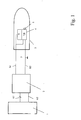
- Fig. 1 is a schematic representation of the general structure of a weapon system with a data-providing unit 1, an ammunition communication system (MKS) 2 and an ammunition unit 3 is shown.
- the ammunition unit 3 comprises a Tempier electronics 4, which is electrically connected to an igniter 5 of the ammunition unit 3.
- the data-providing unit 1 here is preferably a fire control computer.
- the Feuerleitrechner 1 is electrically connected via a data line A1, a CAN bus, and to provide a voltage and power supply U s , I s via a further line A2 to the MKS 2.
- the electrical connection between the MKS 2 and the ammunition unit 3 is provided via the lines B1 and B2, wherein the line B2 represents a ground line and the line B1 for the supply voltage and responsible for the data transfer to the ammunition unit 3.
- the Tempier electronics 4 comprises electrical modules 7 for the programming phase and electrical assemblies 8 for the flight phase.
- FIG. 1 A general structure of the MKS 2 is shown in FIG. 1
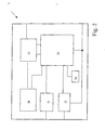
- the MKS 2 has, among other, for clarity, not shown assemblies a voltage supply with voltage modulation 20, a CAN bus interface 21 and a DC / DC converter 22. Outputs and inputs of these assemblies 20 -22 and a quartz oscillator 24 are connected to a microprocessor 25 with a quartz oscillator clock counter 25.1.
- the voltage supply 20 is furthermore connected on the output side to a current demodulator 23, which accesses the microprocessor 25 with two connections.
- a further, preferably bidirectionally operating line of the current demodulator 23 leads in extension as line B1 to the ammunition unit 3.
- the DC / DC converter and the microprocessor 25 each have a connection to a necessary mass, the ammunition unit via line B2 3 connects to the mass.
- Tempier electronics 4 is shown in more detail, with only the essential components are named here. These are a voltage demodulator 30, a current modulator 31 and a microprocessor 32 with an RC oscillator clock counter 32.1. These assemblies 30-32, which are summarized in Figure 1 by the reference numeral 7, are required for programming in the programming phase. For the flight phase, an RC oscillator 33, a tempier counter 34 and an actuator power stage 36 are responsible, which were summarized in Figure 1 by the reference numeral 8. Also shown is a firing sensor 35 which acts as a trigger of the programmed tempier time at the beginning of the flight phase. For the sake of functionality, a voltage regulator 37 is shown, which, however, will not be described in detail.
- the temping is as follows:
- the ammunition-specific data are automatically read out into the fire control computer 1. This determines the necessary temping time for the igniter 5. This information is forwarded to the MKS 2, in which these data are coded by means of microprocessor 25 and the voltage modulation module 20 (HBD-3 code), the coded tempier time pre-set a start byte and appending a stop byte different from the data word of the code.
- the coded signal (see FIG. 4) is transmitted at a baud rate derived from the frequency (clocks) of the quartz oscillator 24 of the MKS 2, counted in the quartz oscillator clock counter 25. 1, and thus precisely defined in time Tempier electronics 4 transmitted and read into the microprocessor 32.
- the clocks of the RC oscillator 33 between the start and stop bytes are measured with the RC oscillator clock counter 32.1. In principle, this would end the programming of the tempier data.
- T ÜB a transmission time T ÜB is calculated with the microprocessor 32 of the Tempier electronics 4. This results from the transmitted data bytes "number of transmitted bits” and "baud rate", which are written as information in the programming in the microprocessor 32 and in the data log of FIG. 4 are shown.
- T UB Number of transmitted bits / baud rate
- the specified baud rate is realized by the quartz-precise microprocessor control in the MKS 2.
- T SHOULD RC T ⁇ 1 - n / T UB ⁇ fuze-timing
- the programming of the tempier counter 34 with the time-corrected T SOLL then results in an almost quartz precision, since the clock frequency of the RC oscillator 32 in the short phase of flight does not appreciably change.
- the firing sensor 35 is a release for the tempier counter 34.
- This then counts with the RC oscillator clock from tempêtmpier setpoint T SOLL from the RC oscillator clock counter 32.1, for example, back to zero and triggers when reaching the actuator -End treat 36 the igniter 5 from.
- the accuracy of the temping can also be adjusted by a specific choice of the data transmission time T ÜB .
Landscapes
- Engineering & Computer Science (AREA)
- General Engineering & Computer Science (AREA)
- Selective Calling Equipment (AREA)
- Electrical Discharge Machining, Electrochemical Machining, And Combined Machining (AREA)
- Preliminary Treatment Of Fibers (AREA)
- Control Of Temperature (AREA)
- Digital Transmission Methods That Use Modulated Carrier Waves (AREA)
- Arrangements For Transmission Of Measured Signals (AREA)
- Synchronisation In Digital Transmission Systems (AREA)
Claims (19)
- Procédé pour régler le temps d'amorçage d'une unité de munition (3) comportant les étapes suivantes :- numérisation du temps de réglage d'amorçage au moyen d'une modulation,- transmission des données codées de réglage du temps d'amorçage dans l'unité de munition (3),- démodulation des données de réglage du temps d'amorçage dans un étage de démodulation (30) de l'unité de munition (3) et transmission des données de réglage du temps d'amorçage à un microprocesseur (32) pour un traitement ultérieur interne en combinaison avec un oscillateur (33) dans l'unité de munition (3), caractérisé en ce que le procédé comprend le fait de placer un multiplet de démarrage et un multiplet d'arrêt.
- Procédé selon la revendication 1, caractérisé en ce qu'une valeur de réglage du temps d'amorçage corrigée en temps (TSOLL) est destinée à l'oscillateur (33).
- Procédé selon la revendication 2, caractérisé en ce que la valeur de réglage du temps d'amorçage corrigée en temps (TSOLL) est déterminée à partir d'un temps de transmission (TÜB)et d'une fréquence d'horloge d'oscillateur (RCT1-n) déterminée.
- Procédé selon la revendication 2 ou 3,
caractérisé en ce que le temps de transmission (TÜB) peut être déterminé à partir du rapport du nombre de bits transmis au débit en bauds. - Procédé selon l'une quelconque des revendications 1 à 4, caractérisé en ce qu'un compteur de réglage du temps d'amorçage (34) de l'unité de munition (3) est programmé avec la valeur de réglage du temps d'amorçage (TSOLL) corrigée en temps.
- Procédé selon l'une quelconque des revendications 1 à 5, caractérisé en ce que les données de réglage du temps d'amorçage numérisées sont transmises par modulation de la tension d'alimentation.
- Procédé selon l'une quelconque des revendications 1 à 6, caractérisé en ce que le code de transmission est un code bipolaire et exempt de courant continu, par exemple un code HDB-3.
- Procédé selon l'une quelconque des revendications 1 à 7, caractérisé en ce que le temps de réglage d'amorçage est transmis numériquement comme multiplet de données entre le multiplet de démarrage et un multiplet d'arrêt.
- Procédé selon l'une quelconque des revendications 1 à 8, caractérisé en ce que le multiplet de démarrage commence par une impulsion de modulation positive et en ce que le multiplet d'arrêt se termine par une impulsion de modulation positive et en ce que le multiplet de démarrage et le multiplet d'arrêt ne sont pas conformes au code de transmission.
- Procédé selon l'une quelconque des revendications 1 à 9, caractérisé en ce qu'une transmission simultanée dans le temps des données de réglage du temps d'amorçage et également de la tension d'alimentation de l'unité de munition (3) est effectuée.
- Procédé selon l'une quelconque des revendications 1 à 10, caractérisé en ce que, en cas d'utilisation d'une puce inscriptible (9) pour données de munition à l'intérieur de l'unité de munition (3), une transmission simultanée des données et de la tension d'alimentation est utile pour la puce pour données de munition (9) et aussi pour l'amorce dont le temps d'amorçage peut être réglé.
- Procédé selon l'une quelconque des revendications 1 à 11, caractérisé en ce qu'une information en retour concernant les données de réglage du temps d'amorçage s'effectue par modulation numérique du courant d'alimentation.
- Dispositif de réglage du temps d'amorçage destiné à un procédé selon les revendications 1 à 12, comprenant une unité (1) fournissant des données de réglage du temps d'amorçage devant être numérisées, des moyens pour placer un multiplet de démarrage et un multiplet d'arrêt et une unité de munition (3) entre lesquelles est intercalé un système (2) faisant fonction également de dispositif extérieur d'alimentation en tension et en courant pour l'unité de munition (3) pendant la transmission de données de réglage du temps d'amorçage.
- Dispositif selon la revendication 13, caractérisé en ce que le système (2) est un système de communication pour munition.
- Dispositif selon la revendication 13 ou 14, caractérisé en ce que le système (2) présente une alimentation en tension avec modulation de tension (20), une interface à bus CAN (21) et un convertisseur CC/CC (22) dont les sorties ainsi que celle d'un oscillateur à quartz (24) sont guidées sur des entrées d'un microprocesseur (25) comportant un compteur d'horloge d'oscillateur à quartz (25.1), l'alimentation en tension (20) étant connectée du côté sortie à un démodulateur de courant (23) qui agit par deux connexions sur le microprocesseur (25).
- Dispositif selon l'une quelconque des revendications 13 à 15, caractérisé en ce que l'unité de munition (3) est connectée pendant la transmission des données de réglage du temps d'amorçage au système (2) connecté en amont et faisant en outre fonction de dispositif extérieur d'alimentation en tension et en courant.
- Unité de munition (3) dont le temps d'amorçage peut être réglé et qui est destinée à un dispositif selon les revendications 13 à 16, présentant- une électronique de réglage du temps d'amorçage (4) comportant des moyens de reconnaissance d'un multiplet de démarrage et d'un multiplet d'arrêt et des modules électriques (7) pour la phase de programmation et des modules électriques (8) pour la phase de vol.
- Unité de munition (3) dont le temps d'amorçage peut être réglé, selon la revendication 17, caractérisée en ce que l'électronique de réglage du temps d'amorçage (4) comportant un oscillateur (33) peut être connectée du côté entrée à un dispositif d'alimentation en tension et en courant et du côté sortie à une amorce (5),- un démodulateur (30) ainsi qu'un microprocesseur (32) étant intégrés dans l'électronique (4) de réglage du temps d'amorçage,- le microprocesseur (32) étant équipé d'un compteur d'horloge pour oscillateur (32.1) et- agissant sur l'oscillateur (33) auquel- sont connectés en aval un compteur de réglage du temps d'amorçage (34) ainsi qu'un étage final d'acteur (36).
- Unité de munition dont le temps d'amorçage peut être réglé, selon la revendication 18, caractérisée en ce que l'oscillateur (33) est un oscillateur RC.
Applications Claiming Priority (2)
| Application Number | Priority Date | Filing Date | Title |
|---|---|---|---|
| DE10152862A DE10152862A1 (de) | 2001-10-25 | 2001-10-25 | Verfahren zur Tempierung einer Munitionseinheit sowie tempierbare Munitionseinheit |
| DE10152862 | 2001-10-25 |
Publications (3)
| Publication Number | Publication Date |
|---|---|
| EP1306644A2 EP1306644A2 (fr) | 2003-05-02 |
| EP1306644A3 EP1306644A3 (fr) | 2003-07-16 |
| EP1306644B1 true EP1306644B1 (fr) | 2006-12-27 |
Family
ID=7703794
Family Applications (1)
| Application Number | Title | Priority Date | Filing Date |
|---|---|---|---|
| EP02020023A Expired - Lifetime EP1306644B1 (fr) | 2001-10-25 | 2002-09-06 | Procédé de programmation pour fusées de munitions et munition avec fusée programmable |
Country Status (5)
| Country | Link |
|---|---|
| EP (1) | EP1306644B1 (fr) |
| AT (1) | ATE349672T1 (fr) |
| DE (2) | DE10152862A1 (fr) |
| ES (1) | ES2277978T3 (fr) |
| IL (1) | IL152464A0 (fr) |
Families Citing this family (2)
| Publication number | Priority date | Publication date | Assignee | Title |
|---|---|---|---|---|
| DE102005030263B3 (de) | 2005-06-29 | 2006-11-30 | Rheinmetall Waffe Munition Gmbh | Sicherheitssystem für tempierbare Munition mit Selbstzerlegung |
| DE102007054382A1 (de) * | 2007-11-14 | 2009-05-20 | Diehl Bgt Defence Gmbh & Co. Kg | De-Letalisierbare Munition |
Family Cites Families (8)
| Publication number | Priority date | Publication date | Assignee | Title |
|---|---|---|---|---|
| US4577561A (en) * | 1982-04-19 | 1986-03-25 | Bei Electronics, Inc. | Digital time fuze method and apparatus |
| US4799429A (en) * | 1984-03-30 | 1989-01-24 | Isc Technologies, Inc. | Programming circuit for individual bomblets in a cluster bomb |
| US4633779A (en) * | 1984-06-29 | 1987-01-06 | Motorola, Inc. | Timing apparatus for a fuse |
| FR2574922B1 (fr) * | 1984-12-18 | 1987-11-13 | France Etat Armement | Fusee a retard programmable pour mise a feu d'elements pyrotechniques |
| CH676882A5 (fr) * | 1988-09-30 | 1991-03-15 | Eidgenoess Munitionsfab Thun | |
| FR2638922B1 (fr) * | 1988-11-07 | 1994-04-29 | Matra | Procede et dispositif de programmation, par voie aerienne, d'une charge externe ou integree a partir d'un vehicule porteur |
| US5894102A (en) * | 1997-12-31 | 1999-04-13 | Aai Corporation | Self-correcting inductive fuze setter |
| DE19827378A1 (de) * | 1998-06-19 | 1999-12-23 | Tzn Forschung & Entwicklung | Waffensystem |
-
2001
- 2001-10-25 DE DE10152862A patent/DE10152862A1/de not_active Ceased
-
2002
- 2002-09-06 DE DE50209063T patent/DE50209063D1/de not_active Expired - Lifetime
- 2002-09-06 ES ES02020023T patent/ES2277978T3/es not_active Expired - Lifetime
- 2002-09-06 AT AT02020023T patent/ATE349672T1/de not_active IP Right Cessation
- 2002-09-06 EP EP02020023A patent/EP1306644B1/fr not_active Expired - Lifetime
- 2002-10-24 IL IL15246402A patent/IL152464A0/xx unknown
Also Published As
| Publication number | Publication date |
|---|---|
| DE10152862A1 (de) | 2003-05-15 |
| ES2277978T3 (es) | 2007-08-01 |
| EP1306644A2 (fr) | 2003-05-02 |
| EP1306644A3 (fr) | 2003-07-16 |
| ATE349672T1 (de) | 2007-01-15 |
| DE50209063D1 (de) | 2007-02-08 |
| IL152464A0 (en) | 2003-05-29 |
Similar Documents
| Publication | Publication Date | Title |
|---|---|---|
| DE102005046350B4 (de) | Anordnung bei einer CAN-Verbindung in einem CAN-System | |
| DE69312609T2 (de) | Programmierbare integrierte Schaltung zur Detonationsverzögerung | |
| DE3103884C2 (fr) | ||
| DE602004003826T2 (de) | Zündbereitschaftsdiagnose einer pyrotechnischen vorrichtung wie eines elektronischen zünders | |
| DE19733748C2 (de) | Datenübertragungsvorrichtung | |
| DE19983678B4 (de) | Bohrloch-Aktivierungssystem | |
| DE2945122C2 (fr) | ||
| DE602004011616T2 (de) | Zünder welcher aufgrund gemessener spannungen zwischen logger- bzw. sprengmodus auswählt | |
| DE602004006439T2 (de) | Dynamische grundlinienbestimmung bei der auf strommodulation basierenden kommunikation | |
| DE2750175A1 (de) | Datenuebertragungssystem mit analog- impulsbreite-digitalumwandlung | |
| EP1574004B1 (fr) | Procede de transmission de donnees sur un bus | |
| DE2357218A1 (de) | Vorrichtung zum vorausberechnen der position eines bewegten teiles, beispielsweise in einem motor | |
| EP0265935A1 (fr) | Emetteur infrarouge de message codé à code fixe et grand nombre de combinaisons | |
| DE102005052578B4 (de) | Verfahren zum Einstellen einer Verzögerungszeit an einem elektronischen Sprengzeitzünder | |
| EP0965815B1 (fr) | Système d'arme | |
| DE3313749A1 (de) | Digitaler zeitgeber und verfahren zur abgabe eines signals | |
| DE3803019C2 (fr) | ||
| DE2552079A1 (de) | Schaltungsanordnung zur bestimmung des mittelwertes einer frequenz | |
| EP1306644A2 (fr) | Procédé de programmation pour fusées de munitions et munition avec fusée programmable | |
| EP3329481B1 (fr) | Procédé de transmission de données d'un capteur à un récepteur | |
| EP1421336B1 (fr) | Systeme de mesure comportant une sortie de frequence ratiometrique | |
| DE102004049084A1 (de) | Sensorschnittstelle mit integrierter Strommessung | |
| US20030136250A1 (en) | Method for fuze-timing an ammunition unit, and fuze-timable ammunition unit | |
| EP1573921A1 (fr) | Oscillateur a commande numerique | |
| WO1991010108A1 (fr) | Detonateur a retard electronique en temps reel |
Legal Events
| Date | Code | Title | Description |
|---|---|---|---|
| PUAI | Public reference made under article 153(3) epc to a published international application that has entered the european phase |
Free format text: ORIGINAL CODE: 0009012 |
|
| AK | Designated contracting states |
Designated state(s): AT BE BG CH CY CZ DE DK EE ES FI FR GB GR IE IT LI LU MC NL PT SE SK TR |
|
| AX | Request for extension of the european patent |
Extension state: AL LT LV MK RO SI |
|
| PUAL | Search report despatched |
Free format text: ORIGINAL CODE: 0009013 |
|
| RIC1 | Information provided on ipc code assigned before grant |
Ipc: 7F 42C 17/04 A Ipc: 7F 42C 11/06 B |
|
| AK | Designated contracting states |
Designated state(s): AT BE BG CH CY CZ DE DK EE ES FI FR GB GR IE IT LI LU MC NL PT SE SK TR |
|
| AX | Request for extension of the european patent |
Extension state: AL LT LV MK RO SI |
|
| 17P | Request for examination filed |
Effective date: 20030606 |
|
| AKX | Designation fees paid |
Designated state(s): AT BE BG CH CY CZ DE DK EE ES FI FR GB GR IE IT LI LU MC NL PT SE SK TR |
|
| 17Q | First examination report despatched |
Effective date: 20040713 |
|
| RAP1 | Party data changed (applicant data changed or rights of an application transferred) |
Owner name: RHEINMETALL LANDSYSTEME GMBH |
|
| GRAP | Despatch of communication of intention to grant a patent |
Free format text: ORIGINAL CODE: EPIDOSNIGR1 |
|
| GRAS | Grant fee paid |
Free format text: ORIGINAL CODE: EPIDOSNIGR3 |
|
| GRAA | (expected) grant |
Free format text: ORIGINAL CODE: 0009210 |
|
| AK | Designated contracting states |
Kind code of ref document: B1 Designated state(s): AT BE BG CH CY CZ DE DK EE ES FI FR GB GR IE IT LI LU MC NL PT SE SK TR |
|
| PG25 | Lapsed in a contracting state [announced via postgrant information from national office to epo] |
Ref country code: FI Free format text: LAPSE BECAUSE OF FAILURE TO SUBMIT A TRANSLATION OF THE DESCRIPTION OR TO PAY THE FEE WITHIN THE PRESCRIBED TIME-LIMIT Effective date: 20061227 Ref country code: IE Free format text: LAPSE BECAUSE OF FAILURE TO SUBMIT A TRANSLATION OF THE DESCRIPTION OR TO PAY THE FEE WITHIN THE PRESCRIBED TIME-LIMIT Effective date: 20061227 Ref country code: CZ Free format text: LAPSE BECAUSE OF FAILURE TO SUBMIT A TRANSLATION OF THE DESCRIPTION OR TO PAY THE FEE WITHIN THE PRESCRIBED TIME-LIMIT Effective date: 20061227 Ref country code: DK Free format text: LAPSE BECAUSE OF FAILURE TO SUBMIT A TRANSLATION OF THE DESCRIPTION OR TO PAY THE FEE WITHIN THE PRESCRIBED TIME-LIMIT Effective date: 20061227 Ref country code: SK Free format text: LAPSE BECAUSE OF FAILURE TO SUBMIT A TRANSLATION OF THE DESCRIPTION OR TO PAY THE FEE WITHIN THE PRESCRIBED TIME-LIMIT Effective date: 20061227 |
|
| REG | Reference to a national code |
Ref country code: GB Ref legal event code: FG4D Free format text: NOT ENGLISH |
|
| REG | Reference to a national code |
Ref country code: IE Ref legal event code: FG4D Free format text: LANGUAGE OF EP DOCUMENT: GERMAN |
|
| REF | Corresponds to: |
Ref document number: 50209063 Country of ref document: DE Date of ref document: 20070208 Kind code of ref document: P |
|
| REG | Reference to a national code |
Ref country code: SE Ref legal event code: TRGR |
|
| REG | Reference to a national code |
Ref country code: CH Ref legal event code: NV Representative=s name: OK PAT AG PATENTE MARKEN LIZENZEN |
|
| PG25 | Lapsed in a contracting state [announced via postgrant information from national office to epo] |
Ref country code: BG Free format text: LAPSE BECAUSE OF FAILURE TO SUBMIT A TRANSLATION OF THE DESCRIPTION OR TO PAY THE FEE WITHIN THE PRESCRIBED TIME-LIMIT Effective date: 20070327 |
|
| ET | Fr: translation filed | ||
| PG25 | Lapsed in a contracting state [announced via postgrant information from national office to epo] |
Ref country code: PT Free format text: LAPSE BECAUSE OF FAILURE TO SUBMIT A TRANSLATION OF THE DESCRIPTION OR TO PAY THE FEE WITHIN THE PRESCRIBED TIME-LIMIT Effective date: 20070528 |
|
| GBV | Gb: ep patent (uk) treated as always having been void in accordance with gb section 77(7)/1977 [no translation filed] |
Effective date: 20061227 |
|
| REG | Reference to a national code |
Ref country code: ES Ref legal event code: FG2A Ref document number: 2277978 Country of ref document: ES Kind code of ref document: T3 |
|
| PLBE | No opposition filed within time limit |
Free format text: ORIGINAL CODE: 0009261 |
|
| STAA | Information on the status of an ep patent application or granted ep patent |
Free format text: STATUS: NO OPPOSITION FILED WITHIN TIME LIMIT |
|
| PG25 | Lapsed in a contracting state [announced via postgrant information from national office to epo] |
Ref country code: GB Free format text: LAPSE BECAUSE OF FAILURE TO SUBMIT A TRANSLATION OF THE DESCRIPTION OR TO PAY THE FEE WITHIN THE PRESCRIBED TIME-LIMIT Effective date: 20061227 |
|
| 26N | No opposition filed |
Effective date: 20070928 |
|
| BERE | Be: lapsed |
Owner name: RHEINMETALL LANDSYSTEME G.M.B.H. Effective date: 20070930 |
|
| PG25 | Lapsed in a contracting state [announced via postgrant information from national office to epo] |
Ref country code: MC Free format text: LAPSE BECAUSE OF NON-PAYMENT OF DUE FEES Effective date: 20070930 Ref country code: GR Free format text: LAPSE BECAUSE OF FAILURE TO SUBMIT A TRANSLATION OF THE DESCRIPTION OR TO PAY THE FEE WITHIN THE PRESCRIBED TIME-LIMIT Effective date: 20070328 |
|
| PG25 | Lapsed in a contracting state [announced via postgrant information from national office to epo] |
Ref country code: BE Free format text: LAPSE BECAUSE OF NON-PAYMENT OF DUE FEES Effective date: 20070930 |
|
| PG25 | Lapsed in a contracting state [announced via postgrant information from national office to epo] |
Ref country code: AT Free format text: LAPSE BECAUSE OF NON-PAYMENT OF DUE FEES Effective date: 20070906 |
|
| PG25 | Lapsed in a contracting state [announced via postgrant information from national office to epo] |
Ref country code: EE Free format text: LAPSE BECAUSE OF FAILURE TO SUBMIT A TRANSLATION OF THE DESCRIPTION OR TO PAY THE FEE WITHIN THE PRESCRIBED TIME-LIMIT Effective date: 20061227 |
|
| PG25 | Lapsed in a contracting state [announced via postgrant information from national office to epo] |
Ref country code: LU Free format text: LAPSE BECAUSE OF NON-PAYMENT OF DUE FEES Effective date: 20070906 Ref country code: CY Free format text: LAPSE BECAUSE OF FAILURE TO SUBMIT A TRANSLATION OF THE DESCRIPTION OR TO PAY THE FEE WITHIN THE PRESCRIBED TIME-LIMIT Effective date: 20061227 |
|
| PG25 | Lapsed in a contracting state [announced via postgrant information from national office to epo] |
Ref country code: TR Free format text: LAPSE BECAUSE OF FAILURE TO SUBMIT A TRANSLATION OF THE DESCRIPTION OR TO PAY THE FEE WITHIN THE PRESCRIBED TIME-LIMIT Effective date: 20061227 |
|
| PGFP | Annual fee paid to national office [announced via postgrant information from national office to epo] |
Ref country code: ES Payment date: 20090922 Year of fee payment: 8 |
|
| PGFP | Annual fee paid to national office [announced via postgrant information from national office to epo] |
Ref country code: NL Payment date: 20090915 Year of fee payment: 8 |
|
| PGFP | Annual fee paid to national office [announced via postgrant information from national office to epo] |
Ref country code: IT Payment date: 20090926 Year of fee payment: 8 |
|
| REG | Reference to a national code |
Ref country code: NL Ref legal event code: V1 Effective date: 20110401 |
|
| PG25 | Lapsed in a contracting state [announced via postgrant information from national office to epo] |
Ref country code: IT Free format text: LAPSE BECAUSE OF NON-PAYMENT OF DUE FEES Effective date: 20100906 |
|
| PG25 | Lapsed in a contracting state [announced via postgrant information from national office to epo] |
Ref country code: NL Free format text: LAPSE BECAUSE OF NON-PAYMENT OF DUE FEES Effective date: 20110401 |
|
| REG | Reference to a national code |
Ref country code: ES Ref legal event code: FD2A Effective date: 20111019 |
|
| PG25 | Lapsed in a contracting state [announced via postgrant information from national office to epo] |
Ref country code: ES Free format text: LAPSE BECAUSE OF NON-PAYMENT OF DUE FEES Effective date: 20100907 |
|
| REG | Reference to a national code |
Ref country code: FR Ref legal event code: PLFP Year of fee payment: 15 |
|
| REG | Reference to a national code |
Ref country code: FR Ref legal event code: PLFP Year of fee payment: 16 |
|
| REG | Reference to a national code |
Ref country code: DE Ref legal event code: R081 Ref document number: 50209063 Country of ref document: DE Owner name: RHEINMETALL WAFFE MUNITION GMBH, DE Free format text: FORMER OWNER: RHEINMETALL LANDSYSTEME GMBH, 24107 KIEL, DE |
|
| REG | Reference to a national code |
Ref country code: FR Ref legal event code: PLFP Year of fee payment: 17 |
|
| REG | Reference to a national code |
Ref country code: CH Ref legal event code: PFUS Owner name: RHEINMETALL LANDSYSTEME GMBH, DE Free format text: FORMER OWNER: RHEINMETALL LANDSYSTEME GMBH, DE |
|
| PGFP | Annual fee paid to national office [announced via postgrant information from national office to epo] |
Ref country code: FR Payment date: 20210921 Year of fee payment: 20 Ref country code: CH Payment date: 20210920 Year of fee payment: 20 |
|
| PGFP | Annual fee paid to national office [announced via postgrant information from national office to epo] |
Ref country code: SE Payment date: 20210920 Year of fee payment: 20 Ref country code: DE Payment date: 20210920 Year of fee payment: 20 |
|
| REG | Reference to a national code |
Ref country code: DE Ref legal event code: R082 Ref document number: 50209063 Country of ref document: DE Representative=s name: DREISS PATENTANWAELTE PARTG MBB, DE |
|
| REG | Reference to a national code |
Ref country code: DE Ref legal event code: R082 Ref document number: 50209063 Country of ref document: DE Representative=s name: DREISS PATENTANWAELTE PARTG MBB, DE |
|
| REG | Reference to a national code |
Ref country code: DE Ref legal event code: R071 Ref document number: 50209063 Country of ref document: DE |
|
| REG | Reference to a national code |
Ref country code: CH Ref legal event code: PL |