EP1306545A2 - Solenoid valve for controlling an injection valve - Google Patents
Solenoid valve for controlling an injection valve Download PDFInfo
- Publication number
- EP1306545A2 EP1306545A2 EP02022596A EP02022596A EP1306545A2 EP 1306545 A2 EP1306545 A2 EP 1306545A2 EP 02022596 A EP02022596 A EP 02022596A EP 02022596 A EP02022596 A EP 02022596A EP 1306545 A2 EP1306545 A2 EP 1306545A2
- Authority
- EP
- European Patent Office
- Prior art keywords
- bore
- section
- valve
- solenoid valve
- sections
- Prior art date
- Legal status (The legal status is an assumption and is not a legal conclusion. Google has not performed a legal analysis and makes no representation as to the accuracy of the status listed.)
- Withdrawn
Links
Images
Classifications
-
- F—MECHANICAL ENGINEERING; LIGHTING; HEATING; WEAPONS; BLASTING
- F02—COMBUSTION ENGINES; HOT-GAS OR COMBUSTION-PRODUCT ENGINE PLANTS
- F02M—SUPPLYING COMBUSTION ENGINES IN GENERAL WITH COMBUSTIBLE MIXTURES OR CONSTITUENTS THEREOF
- F02M47/00—Fuel-injection apparatus operated cyclically with fuel-injection valves actuated by fluid pressure
- F02M47/02—Fuel-injection apparatus operated cyclically with fuel-injection valves actuated by fluid pressure of accumulator-injector type, i.e. having fuel pressure of accumulator tending to open, and fuel pressure in other chamber tending to close, injection valves and having means for periodically releasing that closing pressure
- F02M47/027—Electrically actuated valves draining the chamber to release the closing pressure
-
- F—MECHANICAL ENGINEERING; LIGHTING; HEATING; WEAPONS; BLASTING
- F02—COMBUSTION ENGINES; HOT-GAS OR COMBUSTION-PRODUCT ENGINE PLANTS
- F02M—SUPPLYING COMBUSTION ENGINES IN GENERAL WITH COMBUSTIBLE MIXTURES OR CONSTITUENTS THEREOF
- F02M61/00—Fuel-injectors not provided for in groups F02M39/00 - F02M57/00 or F02M67/00
- F02M61/16—Details not provided for in, or of interest apart from, the apparatus of groups F02M61/02 - F02M61/14
- F02M61/168—Assembling; Disassembling; Manufacturing; Adjusting
-
- F—MECHANICAL ENGINEERING; LIGHTING; HEATING; WEAPONS; BLASTING
- F02—COMBUSTION ENGINES; HOT-GAS OR COMBUSTION-PRODUCT ENGINE PLANTS
- F02M—SUPPLYING COMBUSTION ENGINES IN GENERAL WITH COMBUSTIBLE MIXTURES OR CONSTITUENTS THEREOF
- F02M2200/00—Details of fuel-injection apparatus, not otherwise provided for
- F02M2200/04—Fuel-injection apparatus having means for avoiding effect of cavitation, e.g. erosion
-
- F—MECHANICAL ENGINEERING; LIGHTING; HEATING; WEAPONS; BLASTING
- F02—COMBUSTION ENGINES; HOT-GAS OR COMBUSTION-PRODUCT ENGINE PLANTS
- F02M—SUPPLYING COMBUSTION ENGINES IN GENERAL WITH COMBUSTIBLE MIXTURES OR CONSTITUENTS THEREOF
- F02M2200/00—Details of fuel-injection apparatus, not otherwise provided for
- F02M2200/28—Details of throttles in fuel-injection apparatus
-
- F—MECHANICAL ENGINEERING; LIGHTING; HEATING; WEAPONS; BLASTING
- F02—COMBUSTION ENGINES; HOT-GAS OR COMBUSTION-PRODUCT ENGINE PLANTS
- F02M—SUPPLYING COMBUSTION ENGINES IN GENERAL WITH COMBUSTIBLE MIXTURES OR CONSTITUENTS THEREOF
- F02M63/00—Other fuel-injection apparatus having pertinent characteristics not provided for in groups F02M39/00 - F02M57/00 or F02M67/00; Details, component parts, or accessories of fuel-injection apparatus, not provided for in, or of interest apart from, the apparatus of groups F02M39/00 - F02M61/00 or F02M67/00; Combination of fuel pump with other devices, e.g. lubricating oil pump
- F02M63/0012—Valves
- F02M63/0014—Valves characterised by the valve actuating means
- F02M63/0015—Valves characterised by the valve actuating means electrical, e.g. using solenoid
-
- F—MECHANICAL ENGINEERING; LIGHTING; HEATING; WEAPONS; BLASTING
- F02—COMBUSTION ENGINES; HOT-GAS OR COMBUSTION-PRODUCT ENGINE PLANTS
- F02M—SUPPLYING COMBUSTION ENGINES IN GENERAL WITH COMBUSTIBLE MIXTURES OR CONSTITUENTS THEREOF
- F02M63/00—Other fuel-injection apparatus having pertinent characteristics not provided for in groups F02M39/00 - F02M57/00 or F02M67/00; Details, component parts, or accessories of fuel-injection apparatus, not provided for in, or of interest apart from, the apparatus of groups F02M39/00 - F02M61/00 or F02M67/00; Combination of fuel pump with other devices, e.g. lubricating oil pump
- F02M63/0012—Valves
- F02M63/0031—Valves characterized by the type of valves, e.g. special valve member details, valve seat details, valve housing details
- F02M63/0043—Two-way valves
Definitions
- the invention relates to a solenoid valve for Control of an injection valve according to the preamble of Main claim.
- Such solenoid valves are used for Control of an injector Fuel injection device with a valve needle, the Opening and closing position by the solenoid valve are controllable.
- the solenoid valve has a valve ball, which at Current supply to the solenoid group of the solenoid valve takes off and opens a valve seat.
- This valve seat is above a Bore in fluid communication with the control pressure chamber of the Injector.
- Opening the valve seat builds the pressure in the pressure chamber of the injection valve decreases, whereby Fluid (pressure medium) through the bore towards the valve seat and flows further into a relief room. As a result it to open the valve needle or open the injector.
- the common rail injector works according to this known method of operation (CRI), one main and one Pre-injection realized with very short injection times can be.
- CRI common rail injector
- Such a solenoid valve is known for example from DE 196 50 865 A1.
- the solenoid valve according to the invention has the main claim a bore that is at least partially one or more in the direction of the valve seat continuously in cross section includes widening sections. This will sharp-edged transitions within the bore, in particular in the transition area from the A throttle to the diffuser bore, avoided.
- a conical geometry of the itself is favorable spreading section.
- Valve seat preceding bore several, in particular conically widening towards the valve seat Sections on.
- the conical adjoining the cylindrical bores Sections prevent one, as already mentioned Stall and thus the cause of the formation of Cavitation bubbles.
- the opening angle of the valve seat take successive conical sections suitably too, so that a gradual transition to the opening angle of the valve seat can take place. This causes an extremely favorable flow pattern.
- the continuously widening in cross section Sections can be done in a simple mechanical way generated that the transition between the holes, like A throttle and diffuser bore, is rounded in each case. This makes the existing sharp edge of a Transition already processed in the production so that an optimal flow channel can be created.
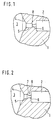
- FIG. 1 is the previous version of a valve piece 1 of a solenoid valve for controlling an injection valve shown.
- the bore 2 leads to the control pressure chamber of the Injector and stands over another throttle bore with the valve seat 4 of the relief chamber 3 of the Solenoid valve in fluid connection.
- the throttle bore is from the so-called A-choke 6 and the following Diffuser bore 5 formed, at the transition point an abrupt one between the cylindrical bores Cross-sectional change occurs.
- valve ball When the solenoid valve is energized, one does not lift shown valve ball in the relief chamber 3 from Valve seat 4, which causes the pressure in the valve chamber Towards the valve ball by using a pressure medium, mostly fuel under high pressure, from hole 2 over the throttle bore flows into the relief chamber 3. The this causes pressure drop in the bore 2 itself upstream control pressure chamber leads to that the valve needle of the injection valve opens and Fuel is injected under high pressure.
- a pressure medium mostly fuel under high pressure
- FIG. 2 shows an embodiment of the invention Solenoid valve in the area of the valve seat 4. Same parts from Figure 1 are in Figure 2 with the same reference numerals Mistake.
- a section 7 is involved continuously expanding cross section in the Throttle bore between the one leading to the control pressure chamber Bore 2 and the relief chamber 3 are provided.
- the exemplary embodiment is section 7 by a method for rounding the hole transition between A throttle 6 and diffuser bore 5 made.
- both the A throttle 6 and the diffuser bore 5 in comparison significantly shortened to the known embodiment according to FIG. 1.
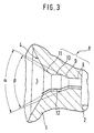
- FIG. 3 Another embodiment of the invention 3 shows the solenoid valve in the area of the valve seat 4.
- this embodiment follows the Control pressure chamber of injector leading bore 2 again the so-called A-choke 6 as cylindrical Bore with a significantly reduced cross section.
- a first conical section 9 follows according to the invention Opening angle ⁇ .
- the diffuser bore 10 is also in this embodiment of a conically widening cross section Section 11 followed, which opens into valve seat 4.
- the conical section 11 has an opening angle ⁇ .
- the opening angle ⁇ is too 50 °, the angle ⁇ selected to 60 °. Overall this will the opening angle of the flow channel successively expanded to then pass into the valve seat. By this measure can make the flow course extremely favorable to be influenced.
- the combination with the strong shortened diffuser bore 10 avoids too strong Pressure increases, the cavitation bubbles that may be present could implode.
- the complete contour of the Flow channel of the bore 8 is schematic in Fig. 3 shown and designated by reference numeral 12.
- the present invention is in any Bore cross-sections can be used, of course also more than two widening in cross section Sections within the bore 8 may be appropriate. In practice it has been shown that the one shown in FIG Is sufficient to prevent the occurrence of To prevent cavitation damage and thus the Functional reliability, in particular of common rail injectors to increase.
Landscapes
- Engineering & Computer Science (AREA)
- Chemical & Material Sciences (AREA)
- Combustion & Propulsion (AREA)
- Mechanical Engineering (AREA)
- General Engineering & Computer Science (AREA)
- Manufacturing & Machinery (AREA)
- Physics & Mathematics (AREA)
- Fluid Mechanics (AREA)
- Fuel-Injection Apparatus (AREA)
- Lift Valve (AREA)
- Details Of Valves (AREA)
- Magnetically Actuated Valves (AREA)
Abstract
Description
Die Erfindung bezieht sich auf ein Magnetventil zur Steuerung eines Einspritzventils gemäß Oberbegriff des Hauptanspruchs. Derartige Magnetventile dienen zur Steuerung eines Einspritzventils einer Kraftstoffeinspritzeinrichtung mit einer Ventilnadel, deren Öffnungs- und Schließstellung durch das Magnetventil steuerbar sind.The invention relates to a solenoid valve for Control of an injection valve according to the preamble of Main claim. Such solenoid valves are used for Control of an injector Fuel injection device with a valve needle, the Opening and closing position by the solenoid valve are controllable.
Das Magnetventil weist eine Ventilkugel auf, die bei Bestromung der Magnetgruppe des Magnetventils abhebt und einen Ventilsitz öffnet. Dieser Ventilsitz steht über eine Bohrung in Fluidverbindung mit dem Steuerdruckraum des Einspritzventils. Bei einem Öffnen des Ventilsitzes baut sich der Druck im Druckraum des Einspritzventils ab, wobei Fluid (Druckmedium) über die Bohrung in Richtung Ventilsitz und weiter in einen Entlastungsraum strömt. In Folge kommt es zum Öffnen der Ventilnadel bzw. Öffnen des Injektors.The solenoid valve has a valve ball, which at Current supply to the solenoid group of the solenoid valve takes off and opens a valve seat. This valve seat is above a Bore in fluid communication with the control pressure chamber of the Injector. When opening the valve seat builds the pressure in the pressure chamber of the injection valve decreases, whereby Fluid (pressure medium) through the bore towards the valve seat and flows further into a relief room. As a result it to open the valve needle or open the injector.
Nach dieser bekannten Arbeitsweise arbeitet der Common-Rail-Injektor (CRI), wobei eine Haupt- und eine Voreinspritzung bei sehr kurzen Einspritzzeiten realisiert werden können. Ein derartiges Magnetventil ist beispielsweise aus der DE 196 50 865 A1 bekannt.The common rail injector works according to this known method of operation (CRI), one main and one Pre-injection realized with very short injection times can be. Such a solenoid valve is known for example from DE 196 50 865 A1.
Es hat sich gezeigt, daß am Ventilsitz des Ventilstücks bei Testläufen z.T. massive Schäden auftreten können, die durch Kavitation verursacht sind. Die im Ventilstück verlaufende Bohrung besteht zunächst aus einer sogenannten zylindrischen A-Drossel, die sich über eine Vorbohrung an den Steuerdruckraum des Einspritzventils anschließt, und aus der darauffolgenden zylindrischen Diffusorbohrung, die zum Ventilsitz führt. Die Kavitationsschäden treten im Bereich des abrupten Übergangs Diffusorbohrung/Ventilsitz auf. Durch diese Schädigungen kommt es zu einem "Unterspülen" der Sitzkante. Mit zunehmendem Schädigungsgrad kommt es zum Ausbrechen dieser Kante und damit zum Totalausfall des Injektors. Damit verbunden ist das Liegenbleiben des Fahrzeugs. Um das beschriebene Problem zu lösen, muß die Bildung der Kavitationsblasen vermindert und der Ort der Implosion etwaiger verbleibender Blasen an eine Stelle verlagert werden, an der diese keinen Einfluß mehr auf die korrekte Injektor-Funktion haben.It has been shown that at the valve seat of the valve piece Test runs partly massive damage can occur through Cavitation are caused. The one running in the valve piece The bore initially consists of a so-called cylindrical A-throttle, which is attached via a pilot hole connects the control pressure chamber of the injection valve, and from the subsequent cylindrical diffuser bore, the leads to the valve seat. The cavitation damage occurs in the Abrupt transition area diffuser bore / valve seat on. This damage leads to "Rinsing" the edge of the seat. With increasing Degree of damage, this edge breaks out and thus the total failure of the injector. Connected with it the vehicle stopping. To the described To solve the problem, the formation of cavitation bubbles diminished and the location of the implosion of any remaining Bubbles are moved to a place where they do not Influence the correct injector function.
Das erfindungsgemäße Magnetventil gemäß Hauptanspruch weist eine Bohrung auf, die zumindest zum Teil einen oder mehrere in Richtung Ventilsitz sich kontinuierlich im Querschnitt verbreiternde Abschnitte beinhaltet. Hierdurch werden scharfkantige Übergänge innerhalb der Bohrung, insbesondere im Übergangsbereich von A-Drossel zur Diffusorbohrung, vermieden. Günstig ist eine konische Geometrie des sich verbreitenden Abschnitts. The solenoid valve according to the invention has the main claim a bore that is at least partially one or more in the direction of the valve seat continuously in cross section includes widening sections. This will sharp-edged transitions within the bore, in particular in the transition area from the A throttle to the diffuser bore, avoided. A conical geometry of the itself is favorable spreading section.
Es hat sich nämlich gezeigt, daß beim Durchströmen des Fluids (Druckmedium) durch die sogenannte A-Drossel an der stromabwärts befindlichen, fertigungstechnisch bedingten, scharfkantigen Austrittskante zur Diffusorbohrung ein starker Strömungsabriß erfolgt. Dort können sich dann Totwasser- und Rezirkulationsgebiete ausbilden. Diese führen unter Umständen zu Schwankungen in der Reproduzierbarkeit der durchströmenden Menge des Fluids sowie zur Bildung von Unterdruckzonen und Kavitationsblasen.It has been shown that when flowing through the Fluids (pressure medium) through the so-called A throttle on the downstream, production-related, sharp-edged trailing edge for diffuser drilling strong stall occurs. There can then Form dead water and recirculation areas. This may lead to fluctuations in the Reproducibility of the amount of fluid flowing through as well as the formation of negative pressure zones and Cavitation bubbles.
Im weiteren Verlauf der Bohrung legt sich die Strömung wieder an die Bohrungswandung an. Kurz vor der im weiteren Verlauf stromabwärts folgenden Drosselstelle am Ventilsitz steigt der Druck im Medium wieder an und die im Flüssigkeitsstrom schwimmenden Kavitationsblasen implodieren und rufen, sofern dies an der Wand des Strömungskanals geschieht, die genannten Kavitationsschäden hervor.In the further course of the drilling, the flow subsides back to the wall of the hole. Shortly before that Course downstream of the throttle at the valve seat the pressure in the medium rises again and that in the Liquid flow floating cavitation bubbles implode and call if this is on the wall of the Flow channel happens, the cavitation damage mentioned out.
Durch die erfindungsgemäß ausgestaltete Bohrung des Magnetventils wird die Strömungsgeometrie im Ventilstück derart geändert, daß ein nahezu turbulenzfreier Übergang des Mediums von der A-Drossel zum Ventilsitz ohne die beschriebenen negativen Auswirkungen erreicht werden kann.Through the inventive bore of the Solenoid valve is the flow geometry in the valve piece changed so that an almost turbulence-free transition of the medium from the A throttle to the valve seat without the described negative effects can be achieved.
Besonders vorteilhaft ist, wenn der Übergang von der A-Drossel zur Diffusorbohrung mit kontinuierlich sich erweiternden Querschnitt ausgebildet wird, so daß die Bohrung insgesamt aus drei ineinander übergehenden Abschnitten besteht. Es kann durch diese Maßnahme ein Abreißen der Strömung an der bisher vorhandenen scharfkantigen Austrittskante verhindert werden. It is particularly advantageous if the transition from the A throttle to the diffuser drilling with continuous itself expanding cross-section is formed so that the A total of three intersecting holes Sections exists. It can be done by this measure Breaking of the flow on the existing one sharp-edged trailing edge can be prevented.
Es hat sich weiterhin gezeigt, daß es vorteilhaft ist, wenn die Bohrung in drei Abschnitte, nämlich A-Drossel und Diffusorbohrung anschließend den im Querschnitt verbreiternden Abschnitt und die Diffusorbohrung, unterteilt wird, wobei A-Drossel und Diffusorbohrung im wesentlichen die gleiche Länge aufweisen. Bei bisherigen Ausgestaltungen schließt sich die A-Drossel unmittelbar an die Diffusorbohrung an, wobei letztere eine größere Länge als erstere aufweist. In der vorliegenden Ausgestaltung können sowohl die A-Drossel als auch die Diffusorbohrung deutlich verkürzt werden, wodurch der Druck insbesondere in der Diffusorbohrung erniedrigt wird. Zusammen mit dem im Querschnitt sich kontinuierlich verbreiternden beispielsweise konischen Übergangsbereich zwischen A-Drossel und Diffusorbohrung erhält man eine optimale Form des Strömungskanals, in dem keine Kavitationsblasen ausgebildet oder Implosionen dieser Blasen beobachtet werden.It has also been shown that it is advantageous if the bore into three sections, namely A throttle and Then the diffuser bore in cross section widening section and the diffuser bore, is divided, with A throttle and diffuser bore in have substantially the same length. With previous ones Refinements immediately follow the A throttle the diffuser bore, the latter being longer as the former. In the present embodiment can use both the A throttle and the diffuser bore can be significantly shortened, which increases the pressure especially in the diffuser hole is lowered. Together with the im Cross section widening continuously for example conical transition area between A-choke and diffuser drilling you get an optimal shape the flow channel in which there are no cavitation bubbles trained or implosions of these bubbles observed become.
In einer anderen vorteilhaften Ausgestaltung weist die dem Ventilsitz vorangehende Bohrung mehrere, insbesondere konisch sich in Richtung Ventilsitz verbreiternde Abschnitte auf. Einen guten Strömungsverlauf kann man erhalten, wenn den beiden zylindrischen Bohrungen, nämlich A-Drossel und Diffusorbohrung, jeweils ein konisch ausgebildeter Abschnitt folgt. Hierdurch kann insbesondere die Länge der (zylindrischen) Diffusorbohrung herabgesetzt werden, so dass der Druckanstieg innerhalb der Diffusorbohrung nicht mehr ausreicht, um etwaige entstandene Kavitationsblasen implodieren zu lassen. Die sich den zylindrischen Bohrungen anschließenden konischen Abschnitte verhindern, wie bereits erwähnt, einen Strömungsabriß und damit die Ursache der Ausbildung von Kavitationsblasen. In another advantageous embodiment, the Valve seat preceding bore several, in particular conically widening towards the valve seat Sections on. You can have a good flow obtained when the two cylindrical holes, namely A throttle and diffuser bore, each one conical trained section follows. This can in particular the length of the (cylindrical) diffuser bore is reduced so that the pressure increase within the Diffuser hole is no longer sufficient to cover any to have implanted cavitation bubbles implode. The conical adjoining the cylindrical bores Sections prevent one, as already mentioned Stall and thus the cause of the formation of Cavitation bubbles.
Die Öffnungswinkel der in Richtung Ventilsitz aufeinanderfolgenden konischen Abschnitte nehmen geeigneterweise zu, so dass ein schrittweiser Übergang auf den Öffnungswinkel des Ventilsitzes erfolgen kann. Dies bewirkt einen äußerst günstigen Strömungsverlauf.The opening angle of the valve seat take successive conical sections suitably too, so that a gradual transition to the opening angle of the valve seat can take place. This causes an extremely favorable flow pattern.
Die sich im Querschnitt kontinuierlich verbreiternden Abschnitte können auf einfache mechanische Weise dadurch erzeugt werden, daß der Übergang zwischen den Bohrungen, wie A-Drossel und Diffusorbohrung, jeweils verrundet wird. Dadurch wird die bisher existierende scharfen Kante eines Übergangs bereits bei der Herstellung so bearbeitet, daß ein optimaler Strömungskanal geschaffen werden kann.The continuously widening in cross section Sections can be done in a simple mechanical way generated that the transition between the holes, like A throttle and diffuser bore, is rounded in each case. This makes the existing sharp edge of a Transition already processed in the production so that an optimal flow channel can be created.
Anhand eines Ausführungsbeispiels soll die Erfindung nachfolgend zusammen mit den beigefügten Figuren erläutert werden.Using an exemplary embodiment, the invention explained below together with the accompanying figures become.
Es zeigen:
Figur 1- einen Schnitt durch das Ventilstück eines Magnetventils in der bisherigen Ausführungsform,
Figur 2- den Schnitt durch das Ventilstück eines erfindungsgemäßen Magnetventils und
Figur 3- den Schnitt durch eine weitere Ausführungsform eines Ventilstücks eines erfindungsgemäßen Magnetventils.
- Figure 1
- 2 shows a section through the valve piece of a solenoid valve in the previous embodiment,
- Figure 2
- the section through the valve piece of a solenoid valve according to the invention and
- Figure 3
- the section through a further embodiment of a valve piece of a solenoid valve according to the invention.
In Figur 1 ist die bisherige Ausführung eines Ventilstücks
1 eines Magnetventils zur Steuerung eines Einspritzventils
dargestellt. Die Bohrung 2 führt zum Steuerdruckraum des
Einspritzventils und steht über eine weitere Drosselbohrung
mit dem Ventilsitz 4 des Entlastungsraumes 3 des
Magnetventils in Fluidverbindung. Die Drosselbohrung ist
aus der sogenannten A-Drossel 6 und der darauffolgenden
Diffusorbohrung 5 gebildet, wobei an der Übergangsstelle
zwischen den zylindrischen Bohrungen eine abrupte
Querschnittsänderung auftritt.In Figure 1 is the previous version of a
Bei Bestromung des Magnetventils hebt eine nicht
dargestellte Ventilkugel im Entlastungsraum 3 vom
Ventilsitz 4 ab, wodurch sich der Druck im Ventilraum in
Richtung Ventilkugel abbauen kann, indem ein Druckmedium,
zumeist Kraftstoff unter Hochdruck, von der Bohrung 2 über
die Drosselbohrung in den Entlastungsraum 3 strömt. Der
hierdurch verursachte Druckabfall in der Bohrung 2 sich
stromaufwärts anschließenden Steuerdruckraum führt dazu,
daß die Ventilnadel des Einspritzventils sich öffnet und
Kraftstoff unter Hochdruck eingespritzt wird.When the solenoid valve is energized, one does not lift
shown valve ball in the
In Figur 1 wird das Gebilde aus A-Drossel 6 und
Diffusorbohrung 5 hier als Drosselbohrung bezeichnet. Bei
einem Hindurchströmen von Fluid (Druckmedium wie Kraftstoff
unter Hochdruck) durch diese Drosselbohrung findet an der
scharfen Kannte des Übergangs von A-Drossel 6 zur
Diffusorbohrung 5 ein Abreißen der Strömung statt. Dies
führt zu Turbulenzen mit sich ausbildenden Totwasser- und
Rezirkulationsgebieten. Das Auseinanderreißen der Strömung
läßt Kavitationsblasen entstehen, die in Hochdruckgebieten
stark verdichtet werden, woraus die Gefahr der Implosion
resultiert. In der Nähe des Ventilsitzes implodierende
Kavitationsblasen können Beschädigungen verursachen, die im
weiteren Verlauf zu einem "Unterspülen" des Ventilsitzes 4
führen können, mit der Folge, daß das ordnungsgemäße Öffnen
und Schließen des Magnetventils und damit des Injektors
nicht mehr garantiert werden können.In Figure 1, the structure of
Figur 2 zeigt eine Ausgestaltung des erfindungsgemäßen
Magnetventils im Bereich des Ventilsitzes 4. Gleiche Teile
aus der Figur 1 sind in Figur 2 mit denselben Bezugszeichen
versehen. Erfindungsgemäß ist ein Abschnitt 7 mit sich
kontinuierlich erweiterndem Querschnitt in der
Drosselbohrung zwischen der zum Steuerdruckraum führenden
Bohrung 2 und dem Entlastungsraum 3 vorgesehen. In diesem
Ausführungsbeispiel ist der Abschnitt 7 durch ein Verfahren
zum Verrunden des Bohrungsübergangs zwischen A-Drossel 6
und Diffusorbohrung 5 hergestellt. Gleichzeitig sind sowohl
die A-Drossel 6 als auch die Diffusorbohrung 5 im Vergleich
zur bekannten Ausführung gemäß Figur 1 deutlich verkürzt.
Die Strömungsgeometrie kann durch diese Maßnahmen in einer
Weise verbessert werden, daß Kavitationsschäden
weitestgehend vermieden werden. Dadurch trägt die Erfindung
erheblich zur Ausfallsicherheit derartiger Ventile, wie sie
für Common-Rail-Injektoren verwendet werden, bei.Figure 2 shows an embodiment of the invention
Solenoid valve in the area of the valve seat 4. Same parts
from Figure 1 are in Figure 2 with the same reference numerals
Mistake. According to the invention, a section 7 is involved
continuously expanding cross section in the
Throttle bore between the one leading to the control
Eine andere Ausführungsform des erfindungsgemäßen
Magnetventils im Bereich des Ventilsitzes 4 zeigt Fig. 3.
Bei dieser Ausgestaltung schließt sich an die zum
Steuerdruckraum des Einspritzventils führende Bohrung 2
wiederum die sogenannte A-Drossel 6 als zylindrische
Bohrung mit deutlich vermindertem Querschnitt an. Hier
folgt erfindungsgemäß ein erster konischer Abschnitt 9 mit
Öffnungswinkel α. Daran schließt sich eine im Vergleich zu
früheren Ausführungsformen (siehe Fig. 1) deutlich
verkürzte Diffusorbohrung 10 von zylindrischer Gestalt an.
Bei dieser Ausführungsform ist auch die Diffusorbohrung 10
von einem sich im Querschnitt konisch erweiternden
Abschnitt 11 gefolgt, der im Ventilsitz 4 mündet. Der
konische Abschnitt 11 weist einen Öffnungswinkel β auf.Another embodiment of the
Bei dem vorliegenden Beispiel ist der Öffnungswinkel α zu
50°, der Winkel β zu 60° gewählt. Insgesamt wird hierdurch
der Öffnungswinkel des Strömungskanals sukzessive
erweitert, um dann in den Ventilsitz überzugehen. Durch
diese Maßnahme kann der Strömungsverlauf äußerst günstig
beeinflusst werden. Die Kombination mit der stark
verkürzten Diffusorbohrung 10 vermeidet zu starke
Druckanstiege, die eventuell vorhandene Kavitationsblasen
implodieren lassen könnten. Die komplette Kontur des
Strömungskanals der Bohrung 8 ist in Fig. 3 schematisch
dargestellt und mit dem Bezugszeichen 12 bezeichnet.In the present example, the opening angle α is too
50 °, the angle β selected to 60 °. Overall this will
the opening angle of the flow channel successively
expanded to then pass into the valve seat. By
this measure can make the flow course extremely favorable
to be influenced. The combination with the strong
shortened diffuser bore 10 avoids too strong
Pressure increases, the cavitation bubbles that may be present
could implode. The complete contour of the
Flow channel of the
Vorliegende Erfindung ist bei beliebigen
Bohrungsquerschnitten einsetzbar, wobei selbstverständlich
auch mehr als zwei sich im Querschnitt verbreiternde
Abschnitte innerhalb der Bohrung 8 zweckmäßig sein können.
In der Praxis hat sich gezeigt, dass der in Fig. 3 gezeigte
Aufbau ausreichend ist, um das Auftreten von
Kavitationsschäden zu verhindern und somit die
Funktionssicherheit insbesondere von Common-Rail-Injektoren
zu erhöhen.The present invention is in any
Bore cross-sections can be used, of course
also more than two widening in cross section
Sections within the
Claims (7)
dadurch gekennzeichnet, daß
die Bohrung (8) zumindest zum Teil einen oder mehrere in Richtung Ventilsitz (4) sich kontinuierlich im Querschnitt verbreiternde Abschnitte (7; 9, 11) aufweist.Solenoid valve for controlling an injection valve of a fuel injection device, the solenoid valve having a valve ball which can be attached to a valve seat (4) of a relief chamber (3) which is in fluid communication with the control pressure chamber of the injection valve via a bore (8),
characterized in that
the bore (8) has at least in part one or more sections (7; 9, 11) which widen continuously in cross section in the direction of the valve seat (4).
Applications Claiming Priority (2)
| Application Number | Priority Date | Filing Date | Title |
|---|---|---|---|
| DE10152173A DE10152173A1 (en) | 2001-10-23 | 2001-10-23 | Solenoid valve for controlling an injection valve |
| DE10152173 | 2001-10-23 |
Publications (2)
| Publication Number | Publication Date |
|---|---|
| EP1306545A2 true EP1306545A2 (en) | 2003-05-02 |
| EP1306545A3 EP1306545A3 (en) | 2005-04-06 |
Family
ID=7703365
Family Applications (1)
| Application Number | Title | Priority Date | Filing Date |
|---|---|---|---|
| EP02022596A Withdrawn EP1306545A3 (en) | 2001-10-23 | 2002-10-09 | Solenoid valve for controlling an injection valve |
Country Status (4)
| Country | Link |
|---|---|
| US (1) | US6834845B2 (en) |
| EP (1) | EP1306545A3 (en) |
| JP (1) | JP2003139018A (en) |
| DE (1) | DE10152173A1 (en) |
Cited By (2)
| Publication number | Priority date | Publication date | Assignee | Title |
|---|---|---|---|---|
| EP2292918A1 (en) * | 2009-07-23 | 2011-03-09 | C.R.F. Società Consortile per Azioni | Fuel injector equipped with a metering servovalve for an internal-combustion engine |
| WO2013016745A1 (en) * | 2011-07-29 | 2013-02-07 | Robert Bosch Gmbh | Throttle bores optimised with respect to cavitation |
Families Citing this family (18)
| Publication number | Priority date | Publication date | Assignee | Title |
|---|---|---|---|---|
| US7832661B2 (en) * | 2003-09-29 | 2010-11-16 | Continental Automotive Systems Us, Inc. | Injector seat that includes a coined seal band with radius |
| JP4519134B2 (en) * | 2003-09-29 | 2010-08-04 | シーメンス ヴィディーオー オートモティヴ コーポレイション | Injector seal with coin seal band |
| DE10355030A1 (en) * | 2003-11-25 | 2005-06-23 | Robert Bosch Gmbh | Valve, in particular for a high-pressure pump of a fuel injection device for an internal combustion engine |
| JP4570149B2 (en) * | 2005-04-05 | 2010-10-27 | 株式会社デンソー | Gas density ratio detection device, concentration detection device, and fuel vapor processing device |
| EP2039802A1 (en) * | 2006-06-21 | 2009-03-25 | Bosch Corporation | Surface treating method by electric discharge, and dressing method |
| DE102007004553A1 (en) | 2007-01-30 | 2008-07-31 | Robert Bosch Gmbh | Ball seat valve for use in injecting device, has diffuser arranged between choke valve and valve seat, and side turned towards seat is provided with narrowing that includes narrowing section turned away from seat |
| US8333336B2 (en) * | 2007-03-06 | 2012-12-18 | Caterpillar Inc. | Cavitation erosion reduction strategy for valve member and fuel injector utilizing same |
| DE102008044096A1 (en) | 2008-11-27 | 2010-06-02 | Robert Bosch Gmbh | Method for producing throttle bores with a low caviation transfer point |
| DE102009045894A1 (en) | 2009-10-21 | 2011-04-28 | Robert Bosch Gmbh | Metal swing frame, has floor anchor attached to frame upper portion, pipe provided on plate for holding swing, and rod obliquely fixed to plate, where rod lies on barrel |
| JP5051279B2 (en) * | 2009-12-21 | 2012-10-17 | 株式会社デンソー | Constant residual pressure valve |
| DE102010028844A1 (en) | 2010-05-11 | 2011-11-17 | Robert Bosch Gmbh | switching valve |
| JP5198511B2 (en) * | 2010-06-29 | 2013-05-15 | 株式会社デンソー | Constant residual pressure valve |
| US9079281B2 (en) * | 2012-03-29 | 2015-07-14 | North American Fuel Systems Remanufacturing, LLC | Common rail valve seat refurbishing |
| DE102013214589A1 (en) * | 2013-07-25 | 2015-01-29 | Robert Bosch Gmbh | Switching valve for a fuel injector |
| DE102015204255A1 (en) * | 2015-03-10 | 2016-09-15 | Robert Bosch Gmbh | Fuel injector for a fuel injection system |
| US10180106B2 (en) | 2016-05-17 | 2019-01-15 | Hamilton Sundstrand Corporation | Solenoids for gas turbine engine bleed valves |
| CN107461271B (en) * | 2017-09-12 | 2023-03-24 | 重庆潍柴发动机有限公司 | Cylinder head |
| RU197666U1 (en) * | 2020-01-27 | 2020-05-21 | Общество с ограниченной ответственностью Управляющая компания "Алтайский завод прецизионных изделий" | FUEL BURNER |
Citations (1)
| Publication number | Priority date | Publication date | Assignee | Title |
|---|---|---|---|---|
| DE19650865A1 (en) | 1996-12-07 | 1998-06-10 | Bosch Gmbh Robert | magnetic valve |
Family Cites Families (11)
| Publication number | Priority date | Publication date | Assignee | Title |
|---|---|---|---|---|
| US3804557A (en) * | 1972-05-26 | 1974-04-16 | A Bentley | Surface operated single tube pump |
| US4640304A (en) * | 1985-03-22 | 1987-02-03 | Baird Manufacturing Company | Overflow vent valve |
| US4946107A (en) * | 1988-11-29 | 1990-08-07 | Pacer Industries, Inc. | Electromagnetic fuel injection valve |
| DE19708104A1 (en) * | 1997-02-28 | 1998-09-03 | Bosch Gmbh Robert | magnetic valve |
| DE19710353A1 (en) * | 1997-03-13 | 1998-09-17 | Bosch Gmbh Robert | Solenoid valve with integrated check valve |
| DE19820341C2 (en) * | 1998-05-07 | 2000-04-06 | Daimler Chrysler Ag | Actuator for a high pressure injector for liquid injection media |
| DE19827267A1 (en) * | 1998-06-18 | 1999-12-23 | Bosch Gmbh Robert | Fuel injection valve for high pressure injection with improved control of the fuel supply |
| DE19859537A1 (en) * | 1998-12-22 | 2000-07-06 | Bosch Gmbh Robert | Fuel injector |
| DE19936667A1 (en) * | 1999-08-04 | 2001-02-22 | Bosch Gmbh Robert | Common rail injector |
| DE19936943A1 (en) * | 1999-08-05 | 2001-02-08 | Bosch Gmbh Robert | Fuel injection valve for internal combustion engine, in which valve closing body is partly spherical |
| DE10007175B9 (en) * | 2000-02-17 | 2004-11-04 | Siemens Ag | Injection valve for injecting fuel into an internal combustion engine |
-
2001
- 2001-10-23 DE DE10152173A patent/DE10152173A1/en not_active Withdrawn
-
2002
- 2002-10-09 EP EP02022596A patent/EP1306545A3/en not_active Withdrawn
- 2002-10-22 JP JP2002307233A patent/JP2003139018A/en not_active Abandoned
- 2002-10-22 US US10/278,596 patent/US6834845B2/en not_active Expired - Fee Related
Patent Citations (1)
| Publication number | Priority date | Publication date | Assignee | Title |
|---|---|---|---|---|
| DE19650865A1 (en) | 1996-12-07 | 1998-06-10 | Bosch Gmbh Robert | magnetic valve |
Cited By (2)
| Publication number | Priority date | Publication date | Assignee | Title |
|---|---|---|---|---|
| EP2292918A1 (en) * | 2009-07-23 | 2011-03-09 | C.R.F. Società Consortile per Azioni | Fuel injector equipped with a metering servovalve for an internal-combustion engine |
| WO2013016745A1 (en) * | 2011-07-29 | 2013-02-07 | Robert Bosch Gmbh | Throttle bores optimised with respect to cavitation |
Also Published As
| Publication number | Publication date |
|---|---|
| JP2003139018A (en) | 2003-05-14 |
| US20030087487A1 (en) | 2003-05-08 |
| EP1306545A3 (en) | 2005-04-06 |
| US6834845B2 (en) | 2004-12-28 |
| DE10152173A1 (en) | 2003-04-30 |
Similar Documents
| Publication | Publication Date | Title |
|---|---|---|
| EP1306545A2 (en) | Solenoid valve for controlling an injection valve | |
| DE69636585T2 (en) | fuel Injector | |
| DE10336223B4 (en) | Filter for insertion into a bore of a fluid channel body | |
| DE19612738C2 (en) | Accumulator injection system for internal combustion engines | |
| DE4243665C2 (en) | Fuel injection device, in particular pump nozzle for internal combustion engines | |
| EP1123461B1 (en) | Compact-size injector for a common-rail-injection system utilized in internal combustion engines | |
| WO2015078629A1 (en) | Fuel injector | |
| DE10245151B4 (en) | Fuel injector | |
| CH686845A5 (en) | Control arrangement for an injection valve for internal combustion engines. | |
| EP1623108A1 (en) | Fuel injection valve for internal combustion engines | |
| EP1574701A1 (en) | Common rail injector | |
| DE102005000639A1 (en) | Pressure modulated common rail injector and injection system | |
| DE19727074B4 (en) | Fuel injection valve for cylinder injection | |
| DE19726099A1 (en) | Fuel injection nozzle | |
| EP1599670B1 (en) | Blind hole and seat hole injection nozzle for an internal combustion engine, comprising a transition cone between the blind hole and the nozzle needle seat | |
| DE102005023179B3 (en) | Injection valve for common rail fuel injection system has drain chamber connected to leakage drilling via restrictor which creates back-pressure to reduce flow of fuel via sealing gaps into drain chamber | |
| DE19843912B4 (en) | fuel Injector | |
| DE102006000187A1 (en) | Fuel injection valve for automotive diesel engine common rail system has plate with a series of apertures | |
| DE10319535A1 (en) | Flow control element for fuel injector, has fluid flowing routes with orifice formed at position separated from route connection portion | |
| EP1176306A2 (en) | Fuel injection system for internal combustion engine | |
| DE10160490B4 (en) | Fuel injection device, fuel system and internal combustion engine | |
| WO2002016760A1 (en) | Fuel injection device for internal combustion engines | |
| DE102007018005A1 (en) | injector | |
| WO2017182298A1 (en) | Valve for opening and closing a line system | |
| DE102019220072A1 (en) | Injector nozzle for injecting fuel under high pressure |
Legal Events
| Date | Code | Title | Description |
|---|---|---|---|
| PUAI | Public reference made under article 153(3) epc to a published international application that has entered the european phase |
Free format text: ORIGINAL CODE: 0009012 |
|
| AK | Designated contracting states |
Designated state(s): AT BE BG CH CY CZ DE DK EE ES FI FR GB GR IE IT LI LU MC NL PT SE SK TR |
|
| AX | Request for extension of the european patent |
Extension state: AL LT LV MK RO SI |
|
| PUAL | Search report despatched |
Free format text: ORIGINAL CODE: 0009013 |
|
| AK | Designated contracting states |
Kind code of ref document: A3 Designated state(s): AT BE BG CH CY CZ DE DK EE ES FI FR GB GR IE IT LI LU MC NL PT SE SK TR |
|
| AX | Request for extension of the european patent |
Extension state: AL LT LV MK RO SI |
|
| AKX | Designation fees paid | ||
| REG | Reference to a national code |
Ref country code: DE Ref legal event code: 8566 |
|
| STAA | Information on the status of an ep patent application or granted ep patent |
Free format text: STATUS: THE APPLICATION IS DEEMED TO BE WITHDRAWN |
|
| 18D | Application deemed to be withdrawn |
Effective date: 20051007 |