EP1306250A1 - Vorrichtung zum Klimatisieren eines Kraftfahrzeugs mit einem Filtergehäuse - Google Patents
Vorrichtung zum Klimatisieren eines Kraftfahrzeugs mit einem Filtergehäuse Download PDFInfo
- Publication number
- EP1306250A1 EP1306250A1 EP02023354A EP02023354A EP1306250A1 EP 1306250 A1 EP1306250 A1 EP 1306250A1 EP 02023354 A EP02023354 A EP 02023354A EP 02023354 A EP02023354 A EP 02023354A EP 1306250 A1 EP1306250 A1 EP 1306250A1
- Authority
- EP
- European Patent Office
- Prior art keywords
- air
- cover
- filter
- filter housing
- opening
- Prior art date
- Legal status (The legal status is an assumption and is not a legal conclusion. Google has not performed a legal analysis and makes no representation as to the accuracy of the status listed.)
- Granted
Links
- 238000004378 air conditioning Methods 0.000 title claims description 35
- 238000009434 installation Methods 0.000 claims description 3
- 238000009423 ventilation Methods 0.000 claims description 3
- 238000007599 discharging Methods 0.000 claims description 2
- 241001417534 Lutjanidae Species 0.000 abstract 1
- 230000000694 effects Effects 0.000 description 3
- 238000010521 absorption reaction Methods 0.000 description 1
- 230000001133 acceleration Effects 0.000 description 1
- 238000009825 accumulation Methods 0.000 description 1
- 230000009286 beneficial effect Effects 0.000 description 1
- 238000010276 construction Methods 0.000 description 1
- 230000001419 dependent effect Effects 0.000 description 1
- 238000009795 derivation Methods 0.000 description 1
- 230000009977 dual effect Effects 0.000 description 1
- 239000000428 dust Substances 0.000 description 1
- 238000001914 filtration Methods 0.000 description 1
- 239000012535 impurity Substances 0.000 description 1
- 238000000034 method Methods 0.000 description 1
- 239000004033 plastic Substances 0.000 description 1
- 238000003672 processing method Methods 0.000 description 1
Images


Classifications
-
- B—PERFORMING OPERATIONS; TRANSPORTING
- B60—VEHICLES IN GENERAL
- B60H—ARRANGEMENTS OF HEATING, COOLING, VENTILATING OR OTHER AIR-TREATING DEVICES SPECIALLY ADAPTED FOR PASSENGER OR GOODS SPACES OF VEHICLES
- B60H3/00—Other air-treating devices
- B60H3/06—Filtering
- B60H3/0608—Filter arrangements in the air stream
- B60H3/0616—Filter arrangements in the air stream with provisions for replacing the filter element
Definitions
- the invention relates to a device for air conditioning a motor vehicle an air conditioning system, a fresh air supply through which the air conditioning system with Fresh air is supplied, an air filter that filters fresh air supplied, one Filter housing for receiving the air filter, an opening in the filter housing for inserting or removing the air filter and a removable one Lid for closing the opening in the filter housing.
- the invention further relates to a filter housing with a cover.
- Generic devices and generic filter housings come for example in front air conditioning systems of motor vehicles, in particular of Trucks, for use.
- Front air conditioners are often installed below the dashboard.
- the air conditioner is generally bolted to the cabin bulkhead and sucks Fresh air through an opening in the front wall.
- To the fresh air of impurities How to clean dust or pollen is on the outside of the cabin bulkhead an air filter is often installed.
- This air filter is inside a filter housing arranged.
- the invention has for its object the disadvantages of the prior art to eliminate and in particular a device for air conditioning a motor vehicle or to provide a filter housing so that in particular, changing the filter insert is made easier.
- the invention builds on the generic device in that the Lid is pivotable about a pivot axis and that the lid is outgoing from its position closing the opening during a pivoting movement is removable when reaching a certain position. In this way access to the filter insert within the filter housing is facilitated because it is no longer necessary to unscrew a lid for this purpose.
- the lid can initially be conveniently moved around a pivot axis swing. In this way, one access or, for example, one Checking the filter insert enables. In the following, the lid can be opened more easily Decrease way as soon as it has reached a predetermined position.
- the device according to the invention is thereby particularly advantageous trained that the installation position of the air filter is selected so that a Air inlet surface is arranged substantially vertically.
- the air generally enters the air filter from below. This also limits the filter area due to the limited overall depth of a vehicle and thus the filter effect.
- the cover in its position closing the opening is substantially parallel to that Air inlet surface of the air filter is arranged.
- the lid thus covers the closed Condition the air inlet area of the air filter. In the open Condition, the air filter is released almost completely, making it a good one Access to the air filter is provided.
- the invention is developed in a particularly advantageous manner in that the lid can be swiveled by approximately 90 ° and that the lid is in its position at the latest fully pivoted position is removable.
- the area of the lid in the closed position is aligned substantially vertically. If you swivel the cover towards the horizontal, it is at the latest when it reaches its end position, i.e. for example the horizontal, removable. But it is also possible to use the hinge respectively to design the hinges of the lid so that it swings out of the Vertical into the horizontal is already removable at an earlier point in time.
- the cover by means of a locking or Snap into place on the filter housing to close the opening can and that the snap or snap connection on the pivot axis opposite side of the lid is arranged.
- a rest or Snap connection is particularly advantageous because the lid is simple can be closed or opened without tools would be required.
- the lid be a Has air inlet opening on the side of the snap or snap connection is arranged that in the area of the air inlet opening, air guiding means for Guiding air into the air inlet opening are provided and that the air guiding means at the same time as a handle for opening or closing the Serve lid.
- the air inlet opening thus allows the air into the air inlet area of the air filter to enter.
- the invention is further advantageously developed in that a condensate drain chamber is formed integrally with the filter housing.
- a condensate drain chamber can with respect to an undisturbed Condensate drain can be optimized.
- the condensate drain chamber can be advantageous Way together with the filter housing by common plastic processing methods to be provided.
- means for removing condensate the condensate drain chamber without any additional aids with the condensate drain chamber are connectable.
- Prior art systems have been commonly used a rubber grommet used to connect a drain hose to the condensate drain connect to.
- the means for removal of condensate are formed as a hose, which on one at the condensate drain chamber arranged nozzle is attachable.
- a neck can be realized in one piece with the condensate drain chamber, so that a particularly simple, yet reliable connection between Hose and condensate drain chamber exist. This can still be improved by placing the hose seat on the neck by a clamp is secured.
- a web is provided in the condensate drain chamber which divides a flow area of the condensate so that a ventilation area is made available. This can result in flooding the condensate drain chamber can be avoided. Avoiding such Flooding is a well-known task related to the expiry of Condensate. For example, the cross section of the To enlarge the condensate drain or to provide tear-off edges that cause a swirl of the condensate and thus an acceleration of the Condensate drain.
- none of these solutions lead to satisfactory results Results while based on the present invention however, a particularly reliable condensate drain through the provision simple means, namely a web in the condensate drain chamber for Is made available.
- the invention is further developed particularly advantageously in such a way that the Filter housing on the motor vehicle is sealed with a first seal, that the condensate drain chamber on the motor vehicle with a second seal is sealed and that the first seal and the second seal in one piece are trained.
- a seal to seal the filter housing is also present in systems of the prior art. It is particularly beneficial to modify this seal in such a way that it is also able to Seal the condensate drain chamber. It is required both air and air to use liquid-tight seals, so that the seal is said can perform dual tasks.
- the invention also consists in a filter housing with a lid for use in a device according to the invention.
- the invention is based on the finding that by providing a pivoting lid makes access to the air filter insert much easier a truck air conditioning system can be made possible.
- a standing arrangement of the Filter insert also allows the use of a significantly larger filter insert and thus reducing the pressure drop in the air conditioning system.
- the hose by dividing the bore of the drain socket with a Provide ventilation so that even if there is a surge of condensate the hole is not flooded. There will always be an even condensate drain guaranteed.
- FIG. 1 shows a sectional view of a device of the prior art. It A part of an air conditioning system 110 is shown schematically as a front air conditioning system below the dashboard of a truck for air conditioning a truck cabin is installed.
- the air conditioner 110 is with the truck bulkhead 144 screwed.
- a fresh air supply 112 is provided, through which the air conditioning system 110 is supplied with fresh air 114.
- An essential component the fresh air supply 112 is a filter housing 118, in which a filter insert 116 is arranged.
- the filter insert 116 has an air inlet surface 124 through which Air 114 can enter the filter insert 116.
- the air is in the filter insert 116 filtered and then enters the air conditioning system 110 as filtered air 140.
- the Filter housing 118 is sealed to the outside by means of a seal 150.
- Condensate accumulating in the air conditioning system 110 passes through a condensate drain 142 from the air conditioning system 110.
- a condensate drain 142 For receiving and removing the condensate is a hose 134 by means of a rubber grommet 152 on the condensate drain 142 connected.
- this special Purpose-dedicated component is required. This is a disadvantage.
- FIG. 1 Disadvantage in the arrangement of the filter insert 116.
- the filter insert 116 is lying arranged, the air inlet surface being positioned horizontally.
- the filter housing 118 is through to allow access to the filter cartridge 116 a cover (not shown) completed by means of screw connections 154 is attached to the filter housing 118.
- the filter insert 116 taken down in the prior art device be, this by additional components 156, which are below the filter housing 118 are located, for example pipes or lines can.
- FIG. 2 shows a sectional view of a device according to the invention. It is a Part of an air conditioning system 10 is shown schematically as a front air conditioning system below the dashboard of a truck for air conditioning one Truck cabin is installed.
- the air conditioning system 10 is screwed to the truck bulkhead 44.
- a fresh air supply 12 is provided through which the air conditioning system 10 fresh air 14 is supplied.
- An essential part of the fresh air supply 12 is a filter housing 18 in which a filter insert 16 is arranged is.
- the filter insert 16 has an air inlet surface 24 through which air 14 enters the Filter insert 16 can occur.
- the air is filtered in the filter insert 16 and then enters the air conditioning system 10 as filtered air 40.
- the filter housing 18 is sealed to the outside by means of a seal 50.
- Condensate accumulating in the air conditioning system 10 passes through a condensate drain 42 from the air conditioning system 10.
- a condensate drain chamber 32 is provided, which is integrally formed with the filter housing 18.
- condensate drain chamber 32 condensate escaping from the air conditioning system 10.
- the condensate drain chamber 32 is equipped with a nozzle 36 on the A hose 34 can easily be plugged on, as shown here is.
- the hose 34 can be further secured by a clamp 46 become.
- there is an uncomplicated connection of the hose 34 for the purpose of condensate absorption, in particular without further Aids can be provided, for example without a rubber grommet (152, Figure 1), as described here in connection with the prior art has been.
- the condensate drain chamber 32 has another remarkable feature , namely a web 38 arranged in the condensate drain chamber 32. In this way, the condensate drain is ventilated, so that also at large amounts of condensate can run off, even with a surge-like Accumulation of condensate.
- the filter insert 16 is covered by a cover 22 which is about a pivot axis 48 arranged in the vicinity of the upper end region of the filter insert 16 is.
- the cover 22 has an air inlet opening 28 in the lower region, into which Fresh air 14 can flow.
- a seal 50 is provided, which is preferably molded in one piece is. This seal 50 seals both the filter housing 18 and the condensate drain chamber 32 to the outside.
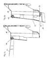
- FIG. 3a shows a sectional view of a filter housing 18 according to the invention with the lid 22 folded up.
- FIG. 3b shows a sectional view of an inventive one Filter housing 18 with the lid 22 closed State of the cover 22 is this via the hinge 48, which the Pivots for the cover 22 forms, as well as via a snap or snap connection 26 firmly connected to the filter housing 18.
- the hinge 48 which the Pivots for the cover 22 forms, as well as via a snap or snap connection 26 firmly connected to the filter housing 18.
- two hinges 48 or a single elongated hinge 48 are provided are or is.
- Different configurations of the locking or Snap connection 26 conceivable, for example several lugs, with the cooperate lower part of the lid 22, or one designed for this purpose elongated lead.
- the cover 22 has an air inlet opening 28.
- the air guide means 30 also serve as a handle to operate, in particular to open the lid 22. It is a robust construction, so that by simply pulling on the lid 22 in the area of the air guiding means 30 overcoming the latching or snap connection 26 is possible, which is also due to the special shape of the air guiding means is stabilized. After opening the lid 22, this can be in the present example, pivot approximately into the horizontal by approximately 90 °.
Landscapes
- Engineering & Computer Science (AREA)
- Mechanical Engineering (AREA)
- Air-Conditioning For Vehicles (AREA)
- Filtering Of Dispersed Particles In Gases (AREA)
Abstract
Description
- Figur 1
- eine Schnittansicht einer Vorrichtung des Standes der Technik;
- Figur 2
- eine Schnittansicht einer erfindungsgemäßen Vorrichtung;
- Figur 3a
- eine Schnittansicht eines erfindungsgemäßen Filtergehäuses mit hochgeklapptem Deckel; und
- Figur 3b
- eine Schnittansicht eines erfindungsgemäßen Filtergehäuses mit geschlossenem Deckel.
- 10
- Klimaanlage
- 12
- Frischluftzuführung
- 14
- Frischluft
- 16
- Filtereinsatz
- 18
- Filtergehäuse
- 20
- Öffnung
- 22
- Deckel
- 24
- Lufteintrittsfläche
- 26
- Rast- oder Schnappverbindung
- 28
- Lufteintrittsöffnung
- 30
- Luftführungsmittel
- 32
- Kondensatablaufkammer
- 34
- Schlauch
- 36
- Stutzen
- 38
- Steg
- 40
- gefilterte Luft
- 42
- Kondensatablauf
- 44
- LKW-Stirnwand
- 46
- Halteschelle
- 48
- Schwenkachse, Scharnier
- 50
- Dichtung
- 110
- Klimaanlage
- 112
- Frischluftzuführung
- 114
- Frischluft
- 116
- Filtereinsatz
- 118
- Filtergehäuse
- 124
- Lufteintrittsfläche
- 134
- Schlauch
- 140
- gefilterte Luft
- 142
- Kondensatablauf
- 144
- LKW-Stirnwand
- 150
- Dichtung
- 152
- Gummitülle
- 154
- Verschraubung
- 156
- weitere Komponenten
Claims (12)
- Vorrichtung zum Klimatisieren eines Kraftfahrzeugs mitdadurch gekennzeichnet,einer Klimaanlage (10),einer Frischluftzuführung (12), durch die die Klimaanlage (10) mit Frischluft (14) versorgt wird,einem Luftfilter (16), der zugeführte Frischluft (14) filtert,einem Filtergehäuse (18) zur Aufnahme des Luftfilters (16),einer Öffnung (20) in dem Filtergehäuse (18) zum Einbringen beziehungsweise Entnehmen des Luftfilters (16) undeinem abnehmbaren Deckel (22) zum Verschließen der Öffnung (20) in dem Filtergehäuse (18),dass der Deckel (22) um eine Schwenkachse (48) schwenkbar ist unddass der Deckel (22), ausgehend von seiner die Öffnung (20) verschließenden Position, während einer Schwenkbewegung beim Erreichen einer bestimmten Position abnehmbar ist.
- Vorrichtung nach Anspruch 1, dadurch gekennzeichnet, dass die Einbaulage des Luftfilters (16) so gewählt ist, dass eine Lufteintrittsfläche (24) im Wesentlichen vertikal angeordnet ist.
- Vorrichtung nach Anspruch 1 oder 2, dadurch gekennzeichnet, dass der Deckel (22) in seiner die Öffnung (20) verschließenden Position im Wesentlichen parallel zu der Lufteintrittsfläche (24) des Luftfilters (16) angeordnet ist.
- Vorrichtung nach einem der vorhergehenden Ansprüche, dadurch gekennzeichnet,dass der Deckel (22) um zirka 90° schwenkbar ist unddass der Deckel (22) spätestens in seiner vollständig ausgeschwenkten Position abnehmbar ist.
- Vorrichtung nach einem der vorhergehenden Ansprüche, dadurch gekennzeichnet,dass der Deckel (22) mittels einer Rast- oder Schnappverbindung (26) an dem Filtergehäuse (18) zum Verschließen der Öffnung (20) einrasten kann unddass die Rast- oder Schnappverbindung (26) an der der Schwenkachse (48) abgewandten Seite des Deckels (22) angeordnet ist.
- Vorrichtung nach einem der vorhergehenden Ansprüche, dadurch gekennzeichnet,dass der Deckel (22) eine Lufteintrittsöffnung (28) aufweist, die auf der Seite der Rast- oder Schnappverbindung (26) angeordnet ist,dass im Bereich der Lufteintrittsöffnung (28) Luftführungsmittel (30) zum Führen von Luft in die Lufteintrittsöffnung (28) vorgesehen sind unddass die Luftführungsmittel (30) gleichzeitig als Griff zum Öffnen beziehungsweise Schließen des Deckels (22) dienen.
- Vorrichtung nach einem der vorhergehenden Ansprüche, dadurch gekennzeichnet, dass einstückig mit dem Filtergehäuse (18) eine Kondensatablaufkammer (32) ausgebildet ist.
- Vorrichtung nach einem der vorhergehenden Ansprüche, dadurch gekennzeichnet, dass Mittel (34) zum Abführen von Kondensat aus der Kondensatablaufkammer (32) ohne weitere Hilfsmittel mit der Kondensatablaufkammer (32) verbindbar sind.
- Vorrichtung nach einem der vorhergehenden Ansprüche, dadurch gekennzeichnet, dass die Mittel zum Abführen von Kondensat als Schlauch (34) ausgebildet sind, der auf einen an der Kondensatablaufkammer (32) angeordneten Stutzen (36) aufsteckbar ist.
- Vorrichtung nach einem der vorhergehenden Ansprüche, dadurch gekennzeichnet, dass in der Kondensatablaufkammer (32) ein Steg (38) vorgesehen ist, der einen Strömungsbereich des Kondensats unterteilt, so dass ein Belüftungsbereich zur Verfügung gestellt wird.
- Vorrichtung nach einem der vorhergehenden Ansprüche, dadurch gekennzeichnet,dass das Filtergehäuse (18) an dem Kraftfahrzeug mit einer ersten Dichtung (50) abgedichtet ist,dass die Kondensatablaufkammer (32) an dem Kraftfahrzeug mit einer zweiten Dichtung (50) abgedichtet ist unddass die erste Dichtung (50) und die zweite Dichtung (50) einstückig ausgebildet sind.
- Filtergehäuse (18) mit Deckel (22) zur Verwendung in einer erfindungsgemäßen Vorrichtung nach einem der Ansprüche 1 bis 11.
Applications Claiming Priority (2)
| Application Number | Priority Date | Filing Date | Title |
|---|---|---|---|
| DE10151618 | 2001-10-23 | ||
| DE10151618A DE10151618C1 (de) | 2001-10-23 | 2001-10-23 | Vorrichtung zum Klimatisieren eines Kraftfahrzeugs und Filtergehäuse |
Publications (2)
| Publication Number | Publication Date |
|---|---|
| EP1306250A1 true EP1306250A1 (de) | 2003-05-02 |
| EP1306250B1 EP1306250B1 (de) | 2005-12-07 |
Family
ID=7703032
Family Applications (1)
| Application Number | Title | Priority Date | Filing Date |
|---|---|---|---|
| EP02023354A Expired - Lifetime EP1306250B1 (de) | 2001-10-23 | 2002-10-18 | Vorrichtung zum Klimatisieren eines Kraftfahrzeugs mit einem Filtergehäuse |
Country Status (3)
| Country | Link |
|---|---|
| EP (1) | EP1306250B1 (de) |
| AT (1) | ATE311995T1 (de) |
| DE (2) | DE10151618C1 (de) |
Cited By (1)
| Publication number | Priority date | Publication date | Assignee | Title |
|---|---|---|---|---|
| EP2532542A1 (de) * | 2011-06-10 | 2012-12-12 | AGCO International GmbH | Luftleitung |
Citations (3)
| Publication number | Priority date | Publication date | Assignee | Title |
|---|---|---|---|---|
| DE19628111C1 (de) * | 1996-07-12 | 1997-07-10 | Mc Micro Compact Car Ag | Fahrzeug |
| FR2769264A1 (fr) * | 1997-10-02 | 1999-04-09 | Valeo Climatisation | Dispositif de chauffage-climatisation pour vehicule automobile, avec groupe moto-ventilateur a filtre a air extractible integre |
| EP1184268A2 (de) * | 2000-08-30 | 2002-03-06 | Deere & Company | Arbeitsfahrzeug, Fahrerkabine und Tür mit einem Frischluftfilter |
Family Cites Families (2)
| Publication number | Priority date | Publication date | Assignee | Title |
|---|---|---|---|---|
| DE4021460A1 (de) * | 1990-07-05 | 1992-01-16 | Behr Gmbh & Co | Gehaeuse mit einem deckel |
| DE19616436C1 (de) * | 1996-04-25 | 1997-04-30 | Daimler Benz Ag | Heizungs- und/oder Klimaanlage für einen Nutzkraftwagen |
-
2001
- 2001-10-23 DE DE10151618A patent/DE10151618C1/de not_active Revoked
-
2002
- 2002-10-18 DE DE50205179T patent/DE50205179D1/de not_active Expired - Fee Related
- 2002-10-18 AT AT02023354T patent/ATE311995T1/de not_active IP Right Cessation
- 2002-10-18 EP EP02023354A patent/EP1306250B1/de not_active Expired - Lifetime
Patent Citations (3)
| Publication number | Priority date | Publication date | Assignee | Title |
|---|---|---|---|---|
| DE19628111C1 (de) * | 1996-07-12 | 1997-07-10 | Mc Micro Compact Car Ag | Fahrzeug |
| FR2769264A1 (fr) * | 1997-10-02 | 1999-04-09 | Valeo Climatisation | Dispositif de chauffage-climatisation pour vehicule automobile, avec groupe moto-ventilateur a filtre a air extractible integre |
| EP1184268A2 (de) * | 2000-08-30 | 2002-03-06 | Deere & Company | Arbeitsfahrzeug, Fahrerkabine und Tür mit einem Frischluftfilter |
Cited By (1)
| Publication number | Priority date | Publication date | Assignee | Title |
|---|---|---|---|---|
| EP2532542A1 (de) * | 2011-06-10 | 2012-12-12 | AGCO International GmbH | Luftleitung |
Also Published As
| Publication number | Publication date |
|---|---|
| EP1306250B1 (de) | 2005-12-07 |
| DE50205179D1 (de) | 2006-01-12 |
| DE10151618C1 (de) | 2003-04-24 |
| ATE311995T1 (de) | 2005-12-15 |
Similar Documents
| Publication | Publication Date | Title |
|---|---|---|
| DE19628089C2 (de) | Belüftungseinrichtung für eine Fahrzeugkabine und Filtergehäuse | |
| DE102011051489C5 (de) | Gebläse-Luftansaugungsvorrichtung | |
| DE19609120C2 (de) | Schneidspan-Absaugeinrichtung zur Verwendung bei einem Schneidwerkzeug | |
| EP1715936B1 (de) | Filtervorrichtung | |
| DE2642083A1 (de) | Luftreiniger | |
| DE102004004197A1 (de) | Zweiteilig ausgebildete Dachstruktur | |
| DE102005012169A1 (de) | Unterhaubenansaugsystem für Motorluft | |
| DE69508186T2 (de) | Fahrzeuggasfühler | |
| DE102007017427A1 (de) | Wasserkastenabdeckung für ein Kraftfahrzeug | |
| WO2018137813A1 (de) | Filterelement mit optimierter strömungsführung | |
| WO2021004827A1 (de) | Kamerasystem mit passivem reinigungssystem für ein kraftfahrzeug | |
| DE19628111C2 (de) | Fahrzeug | |
| WO2020074317A1 (de) | Anbauteil für einen wischerarm | |
| DE10151620B4 (de) | Vorrichtung zum Klimatisieren eines Kraftfahrzeugs und Filtergehäuse | |
| DE102011011975A1 (de) | Luftansaugvorrichtung einer Fahrzeuginnenraumbelüftungsanlage und Fahrzeuginnenraumbelüftungsanlage | |
| DE102007013690A1 (de) | Gehäuseteil für eine Heizungs- und/oder Klimaanlage | |
| DE102014112535B4 (de) | Kraftfahrzeugklimaanlage mit lösbar verbundenem Filterdeckel | |
| WO2002010575A1 (de) | Luftfilter, insbesondere für die ansaugluft einer brennkraftmaschine | |
| EP1306250B1 (de) | Vorrichtung zum Klimatisieren eines Kraftfahrzeugs mit einem Filtergehäuse | |
| DE202018100866U1 (de) | Integrierte Schiebedachentwässerungsleitung | |
| DE10209132B4 (de) | Ansaugvorrichtung für Kaltluft | |
| WO2008148443A1 (de) | Gebläse für ein kraftfahrzeug | |
| DE102019207800A1 (de) | Kondenswasserablaufeinrichtung | |
| DE3142484C1 (de) | "Durch einen Mantel abgedecktes, ein Gebläse aufweisendes Aggregateteil" | |
| EP2698497B1 (de) | Fensteranordnung mit einem Innenfutter |
Legal Events
| Date | Code | Title | Description |
|---|---|---|---|
| PUAI | Public reference made under article 153(3) epc to a published international application that has entered the european phase |
Free format text: ORIGINAL CODE: 0009012 |
|
| AK | Designated contracting states |
Designated state(s): AT BE BG CH CY CZ DE DK EE ES FI FR GB GR IE IT LI LU MC NL PT SE SK TR |
|
| AX | Request for extension of the european patent |
Extension state: AL LT LV MK RO SI |
|
| 17P | Request for examination filed |
Effective date: 20031002 |
|
| AKX | Designation fees paid |
Designated state(s): AT BE BG CH CY CZ DE DK EE ES FI FR GB GR IE IT LI LU MC NL PT SE SK TR |
|
| 17Q | First examination report despatched |
Effective date: 20040212 |
|
| GRAP | Despatch of communication of intention to grant a patent |
Free format text: ORIGINAL CODE: EPIDOSNIGR1 |
|
| GRAS | Grant fee paid |
Free format text: ORIGINAL CODE: EPIDOSNIGR3 |
|
| GRAA | (expected) grant |
Free format text: ORIGINAL CODE: 0009210 |
|
| AK | Designated contracting states |
Kind code of ref document: B1 Designated state(s): AT BE BG CH CY CZ DE DK EE ES FI FR GB GR IE IT LI LU MC NL PT SE SK TR |
|
| PG25 | Lapsed in a contracting state [announced via postgrant information from national office to epo] |
Ref country code: IT Free format text: LAPSE BECAUSE OF FAILURE TO SUBMIT A TRANSLATION OF THE DESCRIPTION OR TO PAY THE FEE WITHIN THE PRESCRIBED TIME-LIMIT;WARNING: LAPSES OF ITALIAN PATENTS WITH EFFECTIVE DATE BEFORE 2007 MAY HAVE OCCURRED AT ANY TIME BEFORE 2007. THE CORRECT EFFECTIVE DATE MAY BE DIFFERENT FROM THE ONE RECORDED. Effective date: 20051207 Ref country code: SK Free format text: LAPSE BECAUSE OF FAILURE TO SUBMIT A TRANSLATION OF THE DESCRIPTION OR TO PAY THE FEE WITHIN THE PRESCRIBED TIME-LIMIT Effective date: 20051207 Ref country code: CZ Free format text: LAPSE BECAUSE OF FAILURE TO SUBMIT A TRANSLATION OF THE DESCRIPTION OR TO PAY THE FEE WITHIN THE PRESCRIBED TIME-LIMIT Effective date: 20051207 Ref country code: NL Free format text: LAPSE BECAUSE OF FAILURE TO SUBMIT A TRANSLATION OF THE DESCRIPTION OR TO PAY THE FEE WITHIN THE PRESCRIBED TIME-LIMIT Effective date: 20051207 Ref country code: GB Free format text: LAPSE BECAUSE OF FAILURE TO SUBMIT A TRANSLATION OF THE DESCRIPTION OR TO PAY THE FEE WITHIN THE PRESCRIBED TIME-LIMIT Effective date: 20051207 Ref country code: IE Free format text: LAPSE BECAUSE OF FAILURE TO SUBMIT A TRANSLATION OF THE DESCRIPTION OR TO PAY THE FEE WITHIN THE PRESCRIBED TIME-LIMIT Effective date: 20051207 Ref country code: FI Free format text: LAPSE BECAUSE OF FAILURE TO SUBMIT A TRANSLATION OF THE DESCRIPTION OR TO PAY THE FEE WITHIN THE PRESCRIBED TIME-LIMIT Effective date: 20051207 |
|
| REG | Reference to a national code |
Ref country code: GB Ref legal event code: FG4D Free format text: NOT ENGLISH |
|
| REG | Reference to a national code |
Ref country code: CH Ref legal event code: EP |
|
| REG | Reference to a national code |
Ref country code: IE Ref legal event code: FG4D Free format text: LANGUAGE OF EP DOCUMENT: GERMAN |
|
| REF | Corresponds to: |
Ref document number: 50205179 Country of ref document: DE Date of ref document: 20060112 Kind code of ref document: P |
|
| PG25 | Lapsed in a contracting state [announced via postgrant information from national office to epo] |
Ref country code: SE Free format text: LAPSE BECAUSE OF FAILURE TO SUBMIT A TRANSLATION OF THE DESCRIPTION OR TO PAY THE FEE WITHIN THE PRESCRIBED TIME-LIMIT Effective date: 20060307 Ref country code: GR Free format text: LAPSE BECAUSE OF FAILURE TO SUBMIT A TRANSLATION OF THE DESCRIPTION OR TO PAY THE FEE WITHIN THE PRESCRIBED TIME-LIMIT Effective date: 20060307 Ref country code: DK Free format text: LAPSE BECAUSE OF FAILURE TO SUBMIT A TRANSLATION OF THE DESCRIPTION OR TO PAY THE FEE WITHIN THE PRESCRIBED TIME-LIMIT Effective date: 20060307 Ref country code: BG Free format text: LAPSE BECAUSE OF FAILURE TO SUBMIT A TRANSLATION OF THE DESCRIPTION OR TO PAY THE FEE WITHIN THE PRESCRIBED TIME-LIMIT Effective date: 20060307 |
|
| PG25 | Lapsed in a contracting state [announced via postgrant information from national office to epo] |
Ref country code: ES Free format text: LAPSE BECAUSE OF FAILURE TO SUBMIT A TRANSLATION OF THE DESCRIPTION OR TO PAY THE FEE WITHIN THE PRESCRIBED TIME-LIMIT Effective date: 20060318 |
|
| PG25 | Lapsed in a contracting state [announced via postgrant information from national office to epo] |
Ref country code: PT Free format text: LAPSE BECAUSE OF FAILURE TO SUBMIT A TRANSLATION OF THE DESCRIPTION OR TO PAY THE FEE WITHIN THE PRESCRIBED TIME-LIMIT Effective date: 20060508 |
|
| NLV1 | Nl: lapsed or annulled due to failure to fulfill the requirements of art. 29p and 29m of the patents act | ||
| GBV | Gb: ep patent (uk) treated as always having been void in accordance with gb section 77(7)/1977 [no translation filed] |
Effective date: 20051207 |
|
| ET | Fr: translation filed | ||
| REG | Reference to a national code |
Ref country code: IE Ref legal event code: FD4D |
|
| PLBE | No opposition filed within time limit |
Free format text: ORIGINAL CODE: 0009261 |
|
| STAA | Information on the status of an ep patent application or granted ep patent |
Free format text: STATUS: NO OPPOSITION FILED WITHIN TIME LIMIT |
|
| PG25 | Lapsed in a contracting state [announced via postgrant information from national office to epo] |
Ref country code: CH Free format text: LAPSE BECAUSE OF NON-PAYMENT OF DUE FEES Effective date: 20061031 Ref country code: LI Free format text: LAPSE BECAUSE OF NON-PAYMENT OF DUE FEES Effective date: 20061031 Ref country code: MC Free format text: LAPSE BECAUSE OF NON-PAYMENT OF DUE FEES Effective date: 20061031 |
|
| 26N | No opposition filed |
Effective date: 20060908 |
|
| REG | Reference to a national code |
Ref country code: CH Ref legal event code: PL |
|
| BERE | Be: lapsed |
Owner name: WEBASTO THERMOSYSTEME INTERNATIONAL G.M.B.H. Effective date: 20061031 |
|
| PG25 | Lapsed in a contracting state [announced via postgrant information from national office to epo] |
Ref country code: AT Free format text: LAPSE BECAUSE OF NON-PAYMENT OF DUE FEES Effective date: 20061018 |
|
| PG25 | Lapsed in a contracting state [announced via postgrant information from national office to epo] |
Ref country code: EE Free format text: LAPSE BECAUSE OF FAILURE TO SUBMIT A TRANSLATION OF THE DESCRIPTION OR TO PAY THE FEE WITHIN THE PRESCRIBED TIME-LIMIT Effective date: 20051207 |
|
| PG25 | Lapsed in a contracting state [announced via postgrant information from national office to epo] |
Ref country code: LU Free format text: LAPSE BECAUSE OF NON-PAYMENT OF DUE FEES Effective date: 20061018 Ref country code: TR Free format text: LAPSE BECAUSE OF FAILURE TO SUBMIT A TRANSLATION OF THE DESCRIPTION OR TO PAY THE FEE WITHIN THE PRESCRIBED TIME-LIMIT Effective date: 20051207 |
|
| REG | Reference to a national code |
Ref country code: FR Ref legal event code: TP |
|
| PG25 | Lapsed in a contracting state [announced via postgrant information from national office to epo] |
Ref country code: CY Free format text: LAPSE BECAUSE OF FAILURE TO SUBMIT A TRANSLATION OF THE DESCRIPTION OR TO PAY THE FEE WITHIN THE PRESCRIBED TIME-LIMIT Effective date: 20051207 |
|
| PGFP | Annual fee paid to national office [announced via postgrant information from national office to epo] |
Ref country code: DE Payment date: 20081016 Year of fee payment: 7 |
|
| PGFP | Annual fee paid to national office [announced via postgrant information from national office to epo] |
Ref country code: IT Payment date: 20081025 Year of fee payment: 7 |
|
| PGFP | Annual fee paid to national office [announced via postgrant information from national office to epo] |
Ref country code: FR Payment date: 20081014 Year of fee payment: 7 |
|
| PG25 | Lapsed in a contracting state [announced via postgrant information from national office to epo] |
Ref country code: BE Free format text: LAPSE BECAUSE OF FAILURE TO SUBMIT A TRANSLATION OF THE DESCRIPTION OR TO PAY THE FEE WITHIN THE PRESCRIBED TIME-LIMIT Effective date: 20061031 |
|
| REG | Reference to a national code |
Ref country code: FR Ref legal event code: ST Effective date: 20100630 |
|
| PG25 | Lapsed in a contracting state [announced via postgrant information from national office to epo] |
Ref country code: FR Free format text: LAPSE BECAUSE OF NON-PAYMENT OF DUE FEES Effective date: 20091102 Ref country code: DE Free format text: LAPSE BECAUSE OF NON-PAYMENT OF DUE FEES Effective date: 20100501 |
|
| PG25 | Lapsed in a contracting state [announced via postgrant information from national office to epo] |
Ref country code: IT Free format text: LAPSE BECAUSE OF NON-PAYMENT OF DUE FEES Effective date: 20091018 |