EP1306249B1 - Air conditioning filter - Google Patents
Air conditioning filter Download PDFInfo
- Publication number
- EP1306249B1 EP1306249B1 EP02023367A EP02023367A EP1306249B1 EP 1306249 B1 EP1306249 B1 EP 1306249B1 EP 02023367 A EP02023367 A EP 02023367A EP 02023367 A EP02023367 A EP 02023367A EP 1306249 B1 EP1306249 B1 EP 1306249B1
- Authority
- EP
- European Patent Office
- Prior art keywords
- container
- filter
- chamber
- cab
- air
- Prior art date
- Legal status (The legal status is an assumption and is not a legal conclusion. Google has not performed a legal analysis and makes no representation as to the accuracy of the status listed.)
- Expired - Lifetime
Links
Images
Classifications
-
- B—PERFORMING OPERATIONS; TRANSPORTING
- B60—VEHICLES IN GENERAL
- B60H—ARRANGEMENTS OF HEATING, COOLING, VENTILATING OR OTHER AIR-TREATING DEVICES SPECIALLY ADAPTED FOR PASSENGER OR GOODS SPACES OF VEHICLES
- B60H3/00—Other air-treating devices
- B60H3/06—Filtering
- B60H3/0608—Filter arrangements in the air stream
- B60H3/0616—Filter arrangements in the air stream with provisions for replacing the filter element
-
- B—PERFORMING OPERATIONS; TRANSPORTING
- B60—VEHICLES IN GENERAL
- B60H—ARRANGEMENTS OF HEATING, COOLING, VENTILATING OR OTHER AIR-TREATING DEVICES SPECIALLY ADAPTED FOR PASSENGER OR GOODS SPACES OF VEHICLES
- B60H1/00—Heating, cooling or ventilating devices
- B60H1/00357—Air-conditioning arrangements specially adapted for particular vehicles
- B60H1/00378—Air-conditioning arrangements specially adapted for particular vehicles for tractor or load vehicle cabins
Definitions
- This invention relates to air conditioning for vehicles, and in particular to the housing of the filter of an air conditioning unit.
- Vehicles such as agricultural tractors and combine harvesters work in dusty environments.
- vehicles are often fitted with air conditioning to maintain the temperature of the operator's cab at an acceptable level.
- the air filtering elements of the air conditioning unit are located in the roof of the cab. They are accessed by removing a hatch on the top of the roof. In order to complete this task it is necessary for the person removing the filter elements to stand on the seat in the tractor cab with his upper body passing through the hatch.
- the filtering element is held in the side of the roof canopy.
- One problem associated with this arrangement is that the filter element is long, flexible and difficult to manipulate. During the procedure of removing the filter from its housing dust may fall out of the filter element.
- USA patent US-5,860,856 discloses a vehicle cab ventilation system according to the preamble of claim 1 which comprises a removable filter housing which houses a filter.
- the filter and filter housing can be extracted as a complete unit downward out of the ventilation system and then removed from the cab for the purpose of cleaning the filters.
- the object of the invention is therefore to provide an improved arrangement for housing the filter element of an air conditioning system for a vehicle having a cab.
- the invention provides a vehicle's operator's cab comprising an enclosed space for the operator, the cab having an air filtration system comprising a chamber located over the enclosed space and housing a removable filter container having a base, four sides, and at least one air inlet opening and at least one air outlet opening, wherein the or each of the air inlet openings are located in the sides of the container, the chamber having an air inlet and an air outlet, a filter housed in the filter container, wherein the filter is slid out of the chamber in the container from a filtering position in the chamber to an emptying position, wherein when the container is in the emptying position the filter element may be removed from the container and the container emptied of debris, and wherein when the container is in the filtering position the said openings are positioned between the air inlet and air outlet of the chamber such that the air may be drawn through the filter into the cab, the system being characterised in that the emptying position is outside the cab and a hatch attached to the exterior of a roof structure of the cab is provided
- FIG. 1 there is shown a cab 1 having a roof 2.
- a filter container 3 is removably mounted in the roof 2, access to the container being provided by hatch 10.
- Hatch 10 is pivotally attached to the structure of roof 2 of the cab 1, and can be moved from a closed position, as shown in Figure 2 , to an open position as shown in Figure 3 .
- the hatch 10 comprises a suitable fastener to fasten the hatch 10 in the position shown in Fig 2 .
- the container 3 consists of five sides, the top being completely open in order that the filter 7 may be freely placed in and removed from the container 3.
- the base and one side of the container are continuous, whilst the continuity of one side and one of the ends are interrupted by openings 6.
- the openings 6 provide pathways for air to be drawn from outside through the elements 8 of the filter 7 and into the cab. Also, air from the cab may be re-circulated from the cab, through the filter and back to the cab.
- FIGs 2 and 5 illustrate the path taken by fresh air drawn in from outside the cab.
- the roof 2 of the cab 1 comprises an air inlet 12. Air is drawn through the inlet and through the elements 8 of the filter 7, the filtered air egressing the filter through the top 9, which comprises suitable apertures. The filtered air passes through ducting and, if required, the air conditioning unit before entering the cab 1 through vents 13 and 14.
- the cab comprises a recirculation door 15. When the driver wishes to recirculate the air in the cab, rather than drawing in fresh air from outside the cab, air is drawn through the grille 15 and via filter 7 back into the cab through vents 13, 14.
- Rails 11 are mounted inside the roof. As can be seen from Figure 3 , the ends of the upper and lower rails 11 are bent in order to facilitate insertion and removal of the filter container 3 from the roof.
- the filter container 3 comprises bosses 5 on opposite sides of the container.
- the bosses 5 are substantially circular and are of diameter slightly less than the distance between the upper and lower rails 11 measured in the vertical direction, thereby providing a sliding fit between the bosses 5 and the rails 11.
- the rails 11 may be formed by plastics mouldings.
- the ends of the rail 11 proximal the hatch 10 comprise indents 17 into which the bosses 5 may drop, thereby permitting the container 3 to brought into a position where the end of the container distal from the bosses 5 is lower than said bosses, without the container being detached from the cab (see Figure 4 ).
- This feature facilitates emptying because the operator does not need to hold both ends of the container whilst removing and/or replacing the filter cartridge.
- Figure 2 shows that when the container 3 complete with the filter 7 is inserted into the roof of the cab, the filter 7 is held in place by frame members 16 which press down on the top 9 of the filter thereby preventing upward movement of the filter 7. This ensures that air entering the container 3 via the fresh air inlet and air intake holes 6 in the container 3 may only pass into the cab through the top 9 of the filter 7 as shown by the arrow "a" in Figure 2 . Absent a seal between the container 3 and the top 9 of the filter 7 air could pass into the cab without passing through the filter.
- the height x of the end of container 3 closest to the hatch 10 is greater than the height y of the end of the container 3 distal from the hatch. Hence, the base of the container 3 is at a slight angle to the horizontal, falling towards the hatch 10.
- the vibrations are transmitted, albeit in attenuated form, to the driver's cab 1.
- the vibrations cause the dust filtered from air passing through the filter element 8 to move towards the end of the container closest to the hatch 10.
- the rails 11 may be mounted in the roof 2 of the cab such that they are at a slight angle to the horizontal, thereby disposing the container 3 at a slight angle to the horizontal.
- the recess into which the container 3 slides is located just above the door which gives access to the operator's cab. Placing the filter in this position renders changing and/or cleaning the element an easy task.
- the operator opens the hatch 10, grips the handle 4 and pulls the container 3, with the filter 7, out of the recess.
- the bosses 5 locate in indents in the slides, and the container 3 is allowed to pivot downwards into the position shown in Figure 4 .
- the operator may then remove the filter 7 for cleaning or replacement. Dust accumulated in the container will fall out of the container through the opening 6 in the end of the container.
- the container 3 may be completely removed from the recess by lifting it out of the indents.
- FIG. 6 A second embodiment of the invention is illustrated in Figures 6 to 10 . Where appropriate, like numerals are used to reference like parts.
- the filter container 3 is similar to that of the first embodiment. However, it is of simpler design, insofar as the sides 20 do not comprise bosses or wheels extending therefrom.
- the roof 2 of the operator's cab comprises a chamber defined by an end wall 22, a floor 23, and sides 24.
- the chamber includes frame members 16 extending across the upper part of the chamber.
- the top 9 of the filter element presses upwardly against the frame members 16, which resist the upward force to securely fasten the filter element in position in the filter container 3.
- the frame members could be replaced by other structures against which the filter element may be pressed, for example the chamber may comprise a substantially flat ceiling formed for a material having sufficient stiffness to resist the upward force exerted by the filter element.
- a locking arrangement comprises a cam member 25 rotatably mounted on to the filter container 3 by a pin 26.
- a handle 26 is attached to the cam member 25. By gripping the handle 26 an operator can rotate the cam member 25 in the direction indicated by the arrow "z". The operator can also grip the handle to withdraw the container 3 from or insert the container 3 into the chamber.
- the hatch 10 shown in Figures 6 to 8 functions in the same manner as the hatch 10 shown in Figures 1 to 3 .
- the floor of the filter container 3 is set a slight angle below the horizontal so the dust and debris settles towards the end of the filter container 3 proximal the hatch 10.
- the invention provides for easy access to the filter, and for the filter to be held in the container as it is extended from the cab.
- the container collects any dust falling from the filter both prior to and during removal of the filter element.
- the potential for exposure of the vehicle operator to dust during the cleaning and/or replacement of the filter is much reduced by this invention.
Landscapes
- Engineering & Computer Science (AREA)
- Mechanical Engineering (AREA)
- Physics & Mathematics (AREA)
- Thermal Sciences (AREA)
- Air-Conditioning For Vehicles (AREA)
- Filtering Of Dispersed Particles In Gases (AREA)
- Air Filters, Heat-Exchange Apparatuses, And Housings Of Air-Conditioning Units (AREA)
Abstract
Description
- This invention relates to air conditioning for vehicles, and in particular to the housing of the filter of an air conditioning unit.
- Vehicles such as agricultural tractors and combine harvesters work in dusty environments. A requirement exists for air entering the operator's cab of such vehicles to be filtered in order to remove dust particles. Furthermore, such vehicles are often fitted with air conditioning to maintain the temperature of the operator's cab at an acceptable level. There is a requirement to filter out dust particles from the air entering an air conditioning system in order to prevent the condenser from becoming blocked. It is necessary to clean or change air filter elements relatively frequently.
- In a current system, the air filtering elements of the air conditioning unit are located in the roof of the cab. They are accessed by removing a hatch on the top of the roof. In order to complete this task it is necessary for the person removing the filter elements to stand on the seat in the tractor cab with his upper body passing through the hatch.
- In another system currently on the market, the filtering element is held in the side of the roof canopy. One problem associated with this arrangement is that the filter element is long, flexible and difficult to manipulate. During the procedure of removing the filter from its housing dust may fall out of the filter element.
- USA patent
US-5,860,856 discloses a vehicle cab ventilation system according to the preamble ofclaim 1 which comprises a removable filter housing which houses a filter. The filter and filter housing can be extracted as a complete unit downward out of the ventilation system and then removed from the cab for the purpose of cleaning the filters. - The object of the invention is therefore to provide an improved arrangement for housing the filter element of an air conditioning system for a vehicle having a cab.
- The invention provides a vehicle's operator's cab comprising an enclosed space for the operator, the cab having an air filtration system comprising a chamber located over the enclosed space and housing a removable filter container having a base, four sides, and at least one air inlet opening and at least one air outlet opening, wherein the or each of the air inlet openings are located in the sides of the container, the chamber having an air inlet and an air outlet, a filter housed in the filter container, wherein the filter is slid out of the chamber in the container from a filtering position in the chamber to an emptying position, wherein when the container is in the emptying position the filter element may be removed from the container and the container emptied of debris, and wherein when the container is in the filtering position the said openings are positioned between the air inlet and air outlet of the chamber such that the air may be drawn through the filter into the cab, the system being characterised in that the emptying position is outside the cab and a hatch attached to the exterior of a roof structure of the cab is provided to close the chamber.
- Further preferable features are set out in the claims dependent on
Claim 1 and appended hereto. - In the drawings, which illustrate an exemplary embodiment of the air conditioning filter housing according to the invention:
-
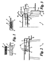
Figure 1 is a schematic representation of the filter and filter housing; -
Figure 2 is a front view of a cab comprising an air conditioning filter housing according to the invention; -
Figure 3 is a front view of the cab shown inFigure 2 , and illustrating access to the filter; -
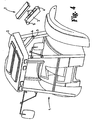
Figure 4 is a schematic representation of a cab comprising an air conditioning filter housing according to the invention; and -
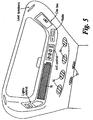
Figure 5 is a schematic representation of the interior of a cab comprising an air conditioning filter housing according to the invention; -
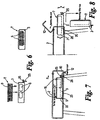
Figure 6 is a schematic representation of the filter and filter housing according to a second embodiment of the invention; -
Figure 7 is a front view of a cab comprising an air conditioning filter housing according to a second embodiment of the invention; -
Figure 8 is a front view of the cab shown inFigure 7 , and illustrating access to the filter; -
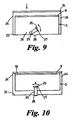
Figure 9 is front view of the filter container with the locking arrangement in the releasing position; and -
Figure 10 is a front view of the filter container with the locking arrangement in the locking position. - Referring now to
Figures 1 to 4 , there is shown acab 1 having a roof 2. A filter container 3 is removably mounted in the roof 2, access to the container being provided byhatch 10. Hatch 10 is pivotally attached to the structure of roof 2 of thecab 1, and can be moved from a closed position, as shown inFigure 2 , to an open position as shown inFigure 3 . Thehatch 10 comprises a suitable fastener to fasten thehatch 10 in the position shown inFig 2 . - The container 3 consists of five sides, the top being completely open in order that the filter 7 may be freely placed in and removed from the container 3. The base and one side of the container are continuous, whilst the continuity of one side and one of the ends are interrupted by openings 6. The openings 6 provide pathways for air to be drawn from outside through the elements 8 of the filter 7 and into the cab. Also, air from the cab may be re-circulated from the cab, through the filter and back to the cab.
-
Figures 2 and5 illustrate the path taken by fresh air drawn in from outside the cab. The roof 2 of thecab 1 comprises anair inlet 12. Air is drawn through the inlet and through the elements 8 of the filter 7, the filtered air egressing the filter through the top 9, which comprises suitable apertures. The filtered air passes through ducting and, if required, the air conditioning unit before entering thecab 1 throughvents recirculation door 15. When the driver wishes to recirculate the air in the cab, rather than drawing in fresh air from outside the cab, air is drawn through thegrille 15 and via filter 7 back into the cab throughvents - Rails 11 are mounted inside the roof. As can be seen from
Figure 3 , the ends of the upper and lower rails 11 are bent in order to facilitate insertion and removal of the filter container 3 from the roof. The filter container 3 comprisesbosses 5 on opposite sides of the container. Thebosses 5 are substantially circular and are of diameter slightly less than the distance between the upper and lower rails 11 measured in the vertical direction, thereby providing a sliding fit between thebosses 5 and the rails 11. The rails 11 may be formed by plastics mouldings. In one embodiment, the ends of the rail 11 proximal thehatch 10 compriseindents 17 into which thebosses 5 may drop, thereby permitting the container 3 to brought into a position where the end of the container distal from thebosses 5 is lower than said bosses, without the container being detached from the cab (seeFigure 4 ). This feature facilitates emptying because the operator does not need to hold both ends of the container whilst removing and/or replacing the filter cartridge. -
Figure 2 shows that when the container 3 complete with the filter 7 is inserted into the roof of the cab, the filter 7 is held in place byframe members 16 which press down on the top 9 of the filter thereby preventing upward movement of the filter 7. This ensures that air entering the container 3 via the fresh air inlet and air intake holes 6 in the container 3 may only pass into the cab through the top 9 of the filter 7 as shown by the arrow "a" inFigure 2 . Absent a seal between the container 3 and the top 9 of the filter 7 air could pass into the cab without passing through the filter. - The height x of the end of container 3 closest to the
hatch 10 is greater than the height y of the end of the container 3 distal from the hatch. Hence, the base of the container 3 is at a slight angle to the horizontal, falling towards thehatch 10. With the engine of the vehicle running small vibrations are induced in the vehicle's chassis. These vibrations are transmitted, albeit in attenuated form, to the driver'scab 1. The vibrations cause the dust filtered from air passing through the filter element 8 to move towards the end of the container closest to thehatch 10. Equally, the rails 11 may be mounted in the roof 2 of the cab such that they are at a slight angle to the horizontal, thereby disposing the container 3 at a slight angle to the horizontal. - As can be seen from
Figure 4 , the recess into which the container 3 slides is located just above the door which gives access to the operator's cab. Placing the filter in this position renders changing and/or cleaning the element an easy task. To change or clean the filter, the operator opens thehatch 10, grips the handle 4 and pulls the container 3, with the filter 7, out of the recess. Thebosses 5 locate in indents in the slides, and the container 3 is allowed to pivot downwards into the position shown inFigure 4 . The operator may then remove the filter 7 for cleaning or replacement. Dust accumulated in the container will fall out of the container through the opening 6 in the end of the container. - The container 3 may be completely removed from the recess by lifting it out of the indents.
- A second embodiment of the invention is illustrated in
Figures 6 to 10 . Where appropriate, like numerals are used to reference like parts. The filter container 3 is similar to that of the first embodiment. However, it is of simpler design, insofar as thesides 20 do not comprise bosses or wheels extending therefrom. The roof 2 of the operator's cab comprises a chamber defined by anend wall 22, afloor 23, and sides 24. As with the first embodiment, the chamber includesframe members 16 extending across the upper part of the chamber. As shown inFigure 7 , with the filter container in the filtering position, the top 9 of the filter element presses upwardly against theframe members 16, which resist the upward force to securely fasten the filter element in position in the filter container 3. The frame members could be replaced by other structures against which the filter element may be pressed, for example the chamber may comprise a substantially flat ceiling formed for a material having sufficient stiffness to resist the upward force exerted by the filter element. - In order to install the filter container in the filtering position, an operator slides it into the chamber until the container comes to rest against a stop, which in this case is the
end wall 22 of the chamber. A locking arrangement comprises acam member 25 rotatably mounted on to the filter container 3 by apin 26. Ahandle 26 is attached to thecam member 25. By gripping thehandle 26 an operator can rotate thecam member 25 in the direction indicated by the arrow "z". The operator can also grip the handle to withdraw the container 3 from or insert the container 3 into the chamber. - It is desirable to lock the container 3 in the position shown in
Figure 7 . This is done by rotating thecam member 25 from the position shown inFigure 9 to that shown inFigure 10 , where thecam member 25 is substantially vertical, and is engaged with anindent 28. Engagement of thecam member 25 with theindent 28 serves two purposes. First, movement of the container in the direction indicated by arrow "m" inFigure 7 is prevented. Second, the filter container is lifted upwardly so the top of the filter 9 engages with theframe members 16 to hold the filter element in place in the container 3. - The
hatch 10 shown inFigures 6 to 8 functions in the same manner as thehatch 10 shown inFigures 1 to 3 . - As with the first embodiment, the floor of the filter container 3 is set a slight angle below the horizontal so the dust and debris settles towards the end of the filter container 3 proximal the
hatch 10. - The invention provides for easy access to the filter, and for the filter to be held in the container as it is extended from the cab. The container collects any dust falling from the filter both prior to and during removal of the filter element. The potential for exposure of the vehicle operator to dust during the cleaning and/or replacement of the filter is much reduced by this invention.
Claims (13)
- A vehicle's operator's cab (1) comprising an enclosed space for the operator, the cab having an air filtration system comprising a chamber located over the enclosed space and housing a removable filter container (3) having a base, four sides, and at least one air inlet opening and at least one air outlet opening (6), wherein the or each of the air inlet openings (6) are located in the sides of the container, the chamber having an air inlet and an air outlet, a filter (7) housed in the filter container, wherein the filter (7) is slid out of the chamber in the container (3) from a filtering position in the chamber to an emptying position, wherein when the container (3) is in the emptying position the filter element (7) may be removed from the container and the container emptied of debris, and wherein when the container (3) is in the filtering position the said openings are positioned between the air inlet and air outlet of the chamber such that the air may be drawn through the filter into the cab, the system being characterised in that
the emptying position is outside the cab and a hatch (10) attached to the exterior of a roof structure of the cab is provided to close the chamber. - A cab according to Claim 1, which includes a locking arrangement for the locking the filter container (3) in the filter position.
- A cab according to Claim 2, wherein the locking arrangement comprises a cam (23) pivotally mounted on the container (3) and pivotable between a filter container locking position in which the cam engages with the chamber (28) and a filter container releasing position in which the cam is disengaged from the chamber.
- A cab according to Claim 3, wherein the chamber (3) has an indent (28), the cam (25) engaging with the indent in the locking position.
- A cab according to any preceding claim, wherein the container (3) comprises a handle (4,26) for easy removal from the chamber.
- A cab according to Claim 5 when dependent on Claim 3 or 4, wherein said handle (26) is attached to said cam (25).
- A cab according to Claim 1, wherein the chamber includes a pair of horizontally spaced slides (11), each slide comprising a pair of vertically spaced rails with a respective boss member (5) on the container which slides between each respective pair of rails.
- A cab according to any preceding claim, wherein the upper part of the chamber comprises at least one element (16) arranged to exert a downward force on the upper part of the filter element (7) when the container (3) is in its filtering position.
- A cab according to Claim 8, wherein the chamber comprises a pair of spaced apart members (16) spaced and located such that with the container (3) and filter element (7) in the filtering position the members (16) exert a downward force on the upper surface of the filter element, substantially on the perimeter of thereof.
- A cab according to any preceding claim, wherein the chamber extends into the roof (2) of the operator's cab (1) in a direction substantially perpendicular to the longitudinal direction of the vehicle.
- A cab according to any preceding claim, wherein the base of the filter container (3) slopes downward towards the end of the chamber nearest the hatch (10).
- A cab according to Claim 7, wherein the slide (5) includes pivot means, which enable the container (3) to pivot downwardly when withdrawn from the chamber.
- A cab according to Claim 12, wherein the pivot means comprises indents (17) in the slides (11), and wherein each boss member (5) locates in its respective slide indent (17) when the container is withdrawn from the chamber to allow the container to pivot downwardly.
Applications Claiming Priority (2)
| Application Number | Priority Date | Filing Date | Title |
|---|---|---|---|
| GB0125694A GB2381216B (en) | 2001-10-26 | 2001-10-26 | Air conditioning filter |
| GB0125694 | 2001-10-26 |
Publications (3)
| Publication Number | Publication Date |
|---|---|
| EP1306249A2 EP1306249A2 (en) | 2003-05-02 |
| EP1306249A3 EP1306249A3 (en) | 2004-01-07 |
| EP1306249B1 true EP1306249B1 (en) | 2012-05-02 |
Family
ID=9924556
Family Applications (1)
| Application Number | Title | Priority Date | Filing Date |
|---|---|---|---|
| EP02023367A Expired - Lifetime EP1306249B1 (en) | 2001-10-26 | 2002-10-18 | Air conditioning filter |
Country Status (4)
| Country | Link |
|---|---|
| US (1) | US6878176B2 (en) |
| EP (1) | EP1306249B1 (en) |
| AT (1) | ATE555931T1 (en) |
| GB (1) | GB2381216B (en) |
Families Citing this family (8)
| Publication number | Priority date | Publication date | Assignee | Title |
|---|---|---|---|---|
| US7258715B2 (en) * | 2004-07-22 | 2007-08-21 | Kaz, Incorporated | Air cleaner |
| US8376820B2 (en) * | 2004-08-26 | 2013-02-19 | Caterpillar Inc. | Fender-accessible air filter |
| FR2908159B1 (en) * | 2006-11-07 | 2009-01-23 | Mark Iv Systemes Moteurs Soc P | DRAWER AIR FILTER DEVICE AND ADMISSION ASSEMBLY COMPRISING SUCH A DEVICE |
| BR102015015456B1 (en) * | 2015-06-25 | 2023-02-28 | Marcopolo S.A | RETURN SYSTEM OF FILTERING ELEMENT RETURN FROM VENTILATION SYSTEMS, AIR CONDITIONING APPLIANCE PROVIDED WITH SAID FILTERING ELEMENT REPLACEMENT SYSTEM AND VEHICLE INCLUDING THE SAME |
| KR101734734B1 (en) * | 2015-12-31 | 2017-05-11 | 현대자동차주식회사 | Intake System of Drawer type Air Cleaner For Improving Maintenance Convenience and Vehicle thereby |
| KR102249595B1 (en) * | 2017-05-16 | 2021-05-10 | 현대자동차 주식회사 | Air cleaner unit for vehicles |
| DE102017115125A1 (en) * | 2017-07-06 | 2019-01-10 | Claas Selbstfahrende Erntemaschinen Gmbh | Canopy of a cabin for an agricultural work vehicle |
| US12491460B2 (en) * | 2021-09-30 | 2025-12-09 | Carrier Corporation | Duct mounted filtering apparatus |
Family Cites Families (15)
| Publication number | Priority date | Publication date | Assignee | Title |
|---|---|---|---|---|
| US3823532A (en) * | 1973-11-14 | 1974-07-16 | Combustion Eng | Filter |
| US4002443A (en) | 1975-03-31 | 1977-01-11 | Massey-Ferguson Inc. | Air filter clamping mechanism for cab |
| US4292060A (en) * | 1978-01-17 | 1981-09-29 | Aisin Sieki Kabushiki Kaisha | Air-filter assembly |
| US4140047A (en) * | 1978-04-07 | 1979-02-20 | Sperry Rand Corporation | Mobile cab with air filter |
| US4242951A (en) * | 1979-08-06 | 1981-01-06 | Cadillac Gage Company | Air intake vent for armored vehicle |
| US4251246A (en) * | 1980-01-24 | 1981-02-17 | Mine Safety Appliances Company | Safety device for side loading filtering apparatus |
| CA1176907A (en) * | 1980-12-08 | 1984-10-30 | Allis-Chalmers Corporation | Downwardly swinging replaceable air filter for a vehicle cab |
| IT1179369B (en) * | 1984-05-15 | 1987-09-16 | Ital Idee Srl | MULTIPLE FILTER GROUP, ESPECIALLY FOR VENTILATION AND AIR CONDITIONING SYSTEMS FOR MOTOR VEHICLES AND CLOSED ENVIRONMENTS, EQUIPPED WITH MEANS OF CONTROL OF EFFICIENCY |
| US4587890A (en) * | 1985-04-15 | 1986-05-13 | Sperry Corporation | Air filtration system for harvester operator cab |
| JP2528288B2 (en) * | 1986-08-21 | 1996-08-28 | 本田技研工業株式会社 | Air cleaner device for motorcycles |
| DE3643478A1 (en) * | 1986-12-19 | 1988-07-07 | Kloeckner Humboldt Deutz Ag | AIR FILTER BOX FOR A DRIVER'S CAB |
| DE19543699C2 (en) * | 1995-11-23 | 1998-07-02 | Daimler Benz Ag | Ventilation device for vehicles |
| DE19628089C2 (en) * | 1996-07-12 | 1998-12-03 | Deere & Co | Ventilation device for a vehicle cabin and filter housing |
| DE19638790A1 (en) * | 1996-09-21 | 1998-03-26 | Mann & Hummel Filter | Air filter |
| DE10034487A1 (en) * | 2000-07-15 | 2002-01-24 | Mhb Filtration Gmbh & Co Kg | in filter |
-
2001
- 2001-10-26 GB GB0125694A patent/GB2381216B/en not_active Expired - Lifetime
-
2002
- 2002-10-18 AT AT02023367T patent/ATE555931T1/en active
- 2002-10-18 EP EP02023367A patent/EP1306249B1/en not_active Expired - Lifetime
- 2002-10-21 US US10/277,168 patent/US6878176B2/en not_active Expired - Lifetime
Also Published As
| Publication number | Publication date |
|---|---|
| GB2381216B (en) | 2005-05-11 |
| GB0125694D0 (en) | 2001-12-19 |
| US20030131572A1 (en) | 2003-07-17 |
| GB2381216A (en) | 2003-04-30 |
| US6878176B2 (en) | 2005-04-12 |
| ATE555931T1 (en) | 2012-05-15 |
| EP1306249A3 (en) | 2004-01-07 |
| EP1306249A2 (en) | 2003-05-02 |
Similar Documents
| Publication | Publication Date | Title |
|---|---|---|
| EP1100650B1 (en) | Hand-held machine tool with dust extraction | |
| DE69721271T2 (en) | Handstaubsauger | |
| CN1705451B (en) | Removable dust collector | |
| EP2897513B1 (en) | Vacuum cleaner with battery lid | |
| EP2637542B1 (en) | Suction cleaner | |
| CA2450058C (en) | Bagless vacuum cleaner | |
| JPH04212619A (en) | Ventilating device for tractor driver's seat | |
| WO1995027634A2 (en) | Stowage compartment, in particular for an umbrella, designed to be fitted in a motor vehicle | |
| US6878176B2 (en) | Air conditioning filter | |
| EP2825083B1 (en) | Suction cleaner with water bath | |
| US4140047A (en) | Mobile cab with air filter | |
| JPH04215519A (en) | Heating apparatus or air conditioner for internal space of automobile | |
| CN114699028B (en) | Cleaning base station | |
| EP4258965B1 (en) | Vacuum apparatus with battery device and filter cleaning device | |
| US5302153A (en) | Air filtering device for a motor vehicle | |
| EP0198543A2 (en) | Air filtration system for operator's cab | |
| DE19942483C1 (en) | Electric vacuum cleaner has dust collection space accessed via hinged cover provided with pivoted dust bag holder for facilitating replacement of dust filter bag | |
| US11684048B2 (en) | Water filter for an aquarium | |
| AU2004202719B2 (en) | Vacuum cleaner | |
| EP0140234B1 (en) | Suction cleaner | |
| DE3537937C2 (en) | Vacuum cleaners, in particular canister vacuum cleaners | |
| CN221044882U (en) | Movable dust suction device | |
| DE3723148A1 (en) | DIRT CLEANER DISPOSAL | |
| JPH061764U (en) | Air cleaner for engine | |
| EP4072389B1 (en) | Suction device, in particular a vacuum cleaner |
Legal Events
| Date | Code | Title | Description |
|---|---|---|---|
| PUAI | Public reference made under article 153(3) epc to a published international application that has entered the european phase |
Free format text: ORIGINAL CODE: 0009012 |
|
| AK | Designated contracting states |
Designated state(s): AT BE BG CH CY CZ DE DK EE ES FI FR GB GR IE IT LI LU MC NL PT SE SK TR |
|
| AX | Request for extension of the european patent |
Extension state: AL LT LV MK RO SI |
|
| PUAL | Search report despatched |
Free format text: ORIGINAL CODE: 0009013 |
|
| AK | Designated contracting states |
Kind code of ref document: A3 Designated state(s): AT BE BG CH CY CZ DE DK EE ES FI FR GB GR IE IT LI LU MC NL PT SE SK TR |
|
| AX | Request for extension of the european patent |
Extension state: AL LT LV MK RO SI |
|
| RIC1 | Information provided on ipc code assigned before grant |
Ipc: 7B 60H 3/00 A Ipc: 7B 60H 3/06 B Ipc: 7B 60H 1/00 B |
|
| 17P | Request for examination filed |
Effective date: 20040130 |
|
| AKX | Designation fees paid |
Designated state(s): AT DE FI FR GB IT |
|
| 17Q | First examination report despatched |
Effective date: 20071102 |
|
| GRAP | Despatch of communication of intention to grant a patent |
Free format text: ORIGINAL CODE: EPIDOSNIGR1 |
|
| GRAS | Grant fee paid |
Free format text: ORIGINAL CODE: EPIDOSNIGR3 |
|
| GRAA | (expected) grant |
Free format text: ORIGINAL CODE: 0009210 |
|
| AK | Designated contracting states |
Kind code of ref document: B1 Designated state(s): AT DE FI FR GB IT |
|
| REG | Reference to a national code |
Ref country code: GB Ref legal event code: FG4D |
|
| REG | Reference to a national code |
Ref country code: AT Ref legal event code: REF Ref document number: 555931 Country of ref document: AT Kind code of ref document: T Effective date: 20120515 |
|
| REG | Reference to a national code |
Ref country code: DE Ref legal event code: R096 Ref document number: 60242785 Country of ref document: DE Effective date: 20120621 |
|
| PG25 | Lapsed in a contracting state [announced via postgrant information from national office to epo] |
Ref country code: FI Free format text: LAPSE BECAUSE OF FAILURE TO SUBMIT A TRANSLATION OF THE DESCRIPTION OR TO PAY THE FEE WITHIN THE PRESCRIBED TIME-LIMIT Effective date: 20120502 |
|
| REG | Reference to a national code |
Ref country code: AT Ref legal event code: MK05 Ref document number: 555931 Country of ref document: AT Kind code of ref document: T Effective date: 20120502 |
|
| PLBE | No opposition filed within time limit |
Free format text: ORIGINAL CODE: 0009261 |
|
| STAA | Information on the status of an ep patent application or granted ep patent |
Free format text: STATUS: NO OPPOSITION FILED WITHIN TIME LIMIT |
|
| PGFP | Annual fee paid to national office [announced via postgrant information from national office to epo] |
Ref country code: AT Payment date: 20121011 Year of fee payment: 11 |
|
| 26N | No opposition filed |
Effective date: 20130205 |
|
| REG | Reference to a national code |
Ref country code: DE Ref legal event code: R097 Ref document number: 60242785 Country of ref document: DE Effective date: 20130205 |
|
| PGFP | Annual fee paid to national office [announced via postgrant information from national office to epo] |
Ref country code: GB Payment date: 20141021 Year of fee payment: 13 |
|
| PGFP | Annual fee paid to national office [announced via postgrant information from national office to epo] |
Ref country code: IT Payment date: 20141028 Year of fee payment: 13 |
|
| REG | Reference to a national code |
Ref country code: FR Ref legal event code: PLFP Year of fee payment: 14 |
|
| GBPC | Gb: european patent ceased through non-payment of renewal fee |
Effective date: 20151018 |
|
| PG25 | Lapsed in a contracting state [announced via postgrant information from national office to epo] |
Ref country code: GB Free format text: LAPSE BECAUSE OF NON-PAYMENT OF DUE FEES Effective date: 20151018 Ref country code: IT Free format text: LAPSE BECAUSE OF NON-PAYMENT OF DUE FEES Effective date: 20151018 |
|
| PG25 | Lapsed in a contracting state [announced via postgrant information from national office to epo] |
Ref country code: AT Free format text: THE PATENT HAS BEEN ANNULLED BY A DECISION OF A NATIONAL AUTHORITY Effective date: 20120502 |
|
| REG | Reference to a national code |
Ref country code: FR Ref legal event code: PLFP Year of fee payment: 15 |
|
| REG | Reference to a national code |
Ref country code: FR Ref legal event code: PLFP Year of fee payment: 16 |
|
| REG | Reference to a national code |
Ref country code: FR Ref legal event code: PLFP Year of fee payment: 17 |
|
| PGFP | Annual fee paid to national office [announced via postgrant information from national office to epo] |
Ref country code: DE Payment date: 20211020 Year of fee payment: 20 |
|
| PGFP | Annual fee paid to national office [announced via postgrant information from national office to epo] |
Ref country code: FR Payment date: 20211021 Year of fee payment: 20 |
|
| REG | Reference to a national code |
Ref country code: DE Ref legal event code: R071 Ref document number: 60242785 Country of ref document: DE |