EP1306246B1 - Verdampfereinheit für eine Transportkälteanlage - Google Patents
Verdampfereinheit für eine Transportkälteanlage Download PDFInfo
- Publication number
- EP1306246B1 EP1306246B1 EP02257385A EP02257385A EP1306246B1 EP 1306246 B1 EP1306246 B1 EP 1306246B1 EP 02257385 A EP02257385 A EP 02257385A EP 02257385 A EP02257385 A EP 02257385A EP 1306246 B1 EP1306246 B1 EP 1306246B1
- Authority
- EP
- European Patent Office
- Prior art keywords
- outer covering
- assembly
- evaporator
- drain pan
- plastic outer
- Prior art date
- Legal status (The legal status is an assumption and is not a legal conclusion. Google has not performed a legal analysis and makes no representation as to the accuracy of the status listed.)
- Expired - Lifetime
Links
Images

Classifications
-
- B—PERFORMING OPERATIONS; TRANSPORTING
- B60—VEHICLES IN GENERAL
- B60H—ARRANGEMENTS OF HEATING, COOLING, VENTILATING OR OTHER AIR-TREATING DEVICES SPECIALLY ADAPTED FOR PASSENGER OR GOODS SPACES OF VEHICLES
- B60H1/00—Heating, cooling or ventilating [HVAC] devices
- B60H1/00507—Details, e.g. mounting arrangements, desaeration devices
- B60H1/00514—Details of air conditioning housings
-
- B—PERFORMING OPERATIONS; TRANSPORTING
- B60—VEHICLES IN GENERAL
- B60H—ARRANGEMENTS OF HEATING, COOLING, VENTILATING OR OTHER AIR-TREATING DEVICES SPECIALLY ADAPTED FOR PASSENGER OR GOODS SPACES OF VEHICLES
- B60H1/00—Heating, cooling or ventilating [HVAC] devices
- B60H1/32—Cooling devices
- B60H1/3233—Cooling devices characterised by condensed liquid drainage means
-
- F—MECHANICAL ENGINEERING; LIGHTING; HEATING; WEAPONS; BLASTING
- F24—HEATING; RANGES; VENTILATING
- F24F—AIR-CONDITIONING; AIR-HUMIDIFICATION; VENTILATION; USE OF AIR CURRENTS FOR SCREENING
- F24F13/00—Details common to, or for air-conditioning, air-humidification, ventilation or use of air currents for screening
- F24F13/22—Means for preventing condensation or evacuating condensate
- F24F13/222—Means for preventing condensation or evacuating condensate for evacuating condensate
Definitions
- This invention relates to a remotely located evaporator assembly including a heating system for a truck climate control system and specifically to construction of a plastic outer covering compatible with the heating system of the evaporator assembly.
- a truck refrigeration system includes a motor and a compressor mounted outside of a cargo area. Refrigerant flows from the compressor into the cargo area to at least one remotely located evaporator unit. The refrigerant flows through an evaporator coil in the evaporator and back to the compressor. Cooling fans mounted within the evaporator blow air across the evaporator coils such that the air is cooled and expelled into the cargo area to maintain a desired temperature.
- One type of evaporator includes a heating system for heating of the compartment and for defrost of the evaporator coils.
- Typical heating systems utilize a hot gas or fluid that is flowed into a separate coil adjacent the evaporator coil.
- Another type of heating system includes electric heating strips positioned below the evaporator coil.
- Evaporators mounted within the cargo area are typically composed of a support housing mounted to an interior surface of the cargo area.
- the evaporator coils and the cooling fans are mounted to the support housing.
- An outer skin conceals and protects the cooling fans and the evaporator coils.
- the outer skin is formed from aluminum.
- One type of evaporator disclosed in co-pending patent application titled “EVAPORATOR WITH PLASTIC OUTER COVERING", serial number 10/003,549, filed October 24, 2001, (published as US-B-6 523 363) and assigned to the applicant of this invention includes a plastic outer covering.
- the plastic outer covering provides design advantages by reducing overall evaporator weight and by simplifying manufacture and assembly.
- the plastic outer cover is not compatible with evaporators having heating system because the plastic material is susceptible to damage from exposure to the heating system.
- US 5295531 is directed towards an evaporator assembly comprising a heater for defrosting the evaporator and a continuous heat shield for protecting the plastic drip tray from heat radiation.
- the present invention provides an evaporator assembly as claimed in claim 1.
- An embodiment of this invention is an evaporator assembly having a heating system and a plastic outer covering protected from damage from radiant heat by a heat shield positioned between the heating system and the plastic outer covering.
- the evaporator assembly includes a support housing for mounting to an internal compartment of a delivery truck or trailer. At least one evaporator coil mounts to the support housing along with at least one cooling fan.
- a heating system is provided, such as a plurality of electric heating strips positioned below the evaporator.
- a plastic outer cover encloses and protects the evaporator coil and cooling fans.
- a drain pan integrally formed within the plastic outer skin collects condensation and moisture dripping from the evaporator coils.
- a heat shield attached between the drain pan and the heating strips attenuates radiant heat that may otherwise damage the plastic outer covering.
- the heat shield includes a plurality of openings to allow moisture to flow through the drain pan.
- An embodiment of the heat shield covers the entire drain pan section of the plastic outer covering. Water and moisture within the drain pan may be sprayed from the interior of the evaporator assembly by the blowing cooling fans causing undesirable dripping of water from the evaporator into the cargo and storage area.
- the heat shield covering the entire drain pan buffets airflow across water within the drain pan to prevent spraying.
- the heat shield attenuates the radiation of heat onto a plastic outer covering to prevent damage and allow the use of a plastic outer covering in evaporator assemblies including heating systems to realize of cost and weight benefits associated with the use of plastic outer coverings.
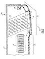
- the evaporator 10 includes a support housing 12 mounted within climate controlled space.
- the support housing 12 includes first and second sides 11, 13 that include inlet an outlet tubing 22 from a compressor (not shown).
- At least one evaporator coil 14 (Figure 2) attaches to the support housing 12 and is connected by way of the inlet and outlet tubing 22 to the compressor.
- Evaporator assemblies 10 including two evaporator coils 14 are known as dual discharge and those having only one evaporator coil 14 are signal discharge evaporators.
- At least one electric fan 16 mounts 16 to the support housing 12 to circulate and force airflow over the evaporator coils 14.
- the evaporator assembly 10 shown in Figure 1 is a dual discharge evaporator including two evaporator coils 14 with the electric fans 16 mounted between the evaporator coils 14.
- the number of electric fans 16 is dependent on the specific configuration of the evaporator assembly 10.
- the electric fans 16 can be of any type known in the art.
- the evaporator coils 14 include electric heating elements 36 to defrost the evaporator coils 14 and/or provide heat for controlling the climate in a specific storage area.
- the heating elements 36 are preferably attached to a bottom side of the evaporator coil 14.
- the plastic outer covering 18 includes a hinge portion 28 that engages a portion of the support housing 12 to form a hinge connection to allow access to the interior of the evaporator assembly 10 without the need to completely remove the outer covering 18.
- the outer cover 18 is further attached to the support housing 12 on a side opposite the hinge 28 by way of fasteners 35 extending through mounting openings 34.
- the outer covering 18 includes an integrally formed drain pan section 24 and panel section 26.
- the panel section 26 extends over a center section of the evaporator assembly 10 where the electric fans 16 are mounted.
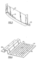
- the drain pan section 24 is formed as part of a profile 38 of the outer covering 18.
- the outer covering 18 is formed in a plastic extrusion process known in the art as pultrusion. In this process, plastic material is pushed through a die having the desired profile. This process produces lengths of plastic outer coverings 18 with the desired profile 38. The lengths are then cut to the proper length for assembly to the evaporator assembly 10.
- the use of the plastic outer covering 18 provides numerous cost and assembly efficiencies and is therefore desirable for use in constructing evaporator assemblies 10.
- end caps 20 are attached to form sides of the drain pan 24.
- the end caps 20 are preferably fabricated from plastic material that is adhered to the sides of the outer covering 18 by an industrial adhesive to forms a watertight joint.
- the end caps 20 include a series of tabs 40 that form a channel into which the outer covering 18 fits to hold and align the end cap 20 to the outer covering 18.
- At least one of the end caps 20 includes a drain tube 30 for attachment to a drain hose (not shown) to carry water and moisture from the drain pan 24.
- the fabrication of the outer covering 18 from plastic provides many benefits to the production of evaporators. These include, as discussed hereinabove, reduced cost and ease of manufacture, along with the favorable thermal properties of the plastic material that eliminates the need for a layer of insulation to prevent condensation built up on the outside of the cover.
- the plastic outer covering 18 is a problem.
- the heat from the electric heaters 36 can cause deformation of the plastic outer covering 18.
- the evaporator 10 of this invention includes a heat shield 44 disposed between the plastic outer covering 18 and the electric heater 36 to attenuate heat radiated onto the plastic outer covering 18.
- the heat shield 44 is fabricated from a material unaffected by the heat produced by the electric heaters 36.
- the heat shield 44 is fabricated from metal formed to fit over the drain pan section of the outer covering.
- the heat shield 44 attaches to the drain pan section 24 to diffuse the amount of heat radiated from the electric heaters 36 such that the plastic outer covering 18 is not damaged.
- a plurality of openings 46 are disposed in the heat shield 44 to allow for the flow of water from the evaporator coils 14 through the heat shield 44 and into the drain pan 24. Airflow from the fans 16 not only flows through the evaporator coils 14 but also over water within the drain pan 24.
- the heat shield 44 includes a spray shield section 48 that prevents airflow from spraying water in the drain pan 24 from the interior of the evaporator assembly 10.
Landscapes
- Physics & Mathematics (AREA)
- Thermal Sciences (AREA)
- Engineering & Computer Science (AREA)
- Mechanical Engineering (AREA)
- Removal Of Water From Condensation And Defrosting (AREA)
- Devices For Blowing Cold Air, Devices For Blowing Warm Air, And Means For Preventing Water Condensation In Air Conditioning Units (AREA)
- Defrosting Systems (AREA)
- Devices That Are Associated With Refrigeration Equipment (AREA)
Claims (10)
- Verdampferanordnung (10), aufweisend:dadurch gekennzeichnet, dass ein Wärmeschild (44) zwischen der Kunststoffaußenabdeckung (18) und der Heizeinrichtung (36) angeordnet ist, um die an die Kunststoffaußenabdeckung (18) abgestrahlte Wärme abzuschwächen; und dadurch,eine Verdampferwindung (14), die an einem Stützgehäuse (12) angebracht ist;ein Gebläse (16), das an dem Stützgehäuse (12) angebracht ist;eine Heizeinrichtung (36), die der Verdampferwindung (14) benachbart angeordnet ist;eine Kunststoffaußenabdeckung (18), die einen integral gebildeten Ablaufwannenabschnitt (24) aufweist;
dass das Wärmeschild (44) über der Ablaufwanne (24) angeordnet ist und eine Mehrzahl von Öffnungen (46) aufweist, um es Feuchtigkeit zu ermöglichen, durch das Wärmeschild (44) und in die Ablaufwanne (24) zu fließen. - Anordnung nach Anspruch 1, ferner aufweisend Abschlusskappen (20), die an der Kunststoffaußenabdeckung (18) an dem Ablaufwannenabschnitt (24) angebracht sind, wobei eine der Abschlusskappen (20) ein Ablaufrohr (30) aufweist, das positioniert ist, um Feuchtigkeit von der integral gebildeten Ablaufwanne (24) abzuleiten.
- Anordnung nach Anspruch 2, wobei die Abschlusskappen (20) mittels eines Klebstoffs an der Außenabdeckung (18) angebracht sind.
- Anordnung nach Anspruch 1, 2 oder 3, wobei das Wärmeschild (44) an der Kunststoffaußenabdeckung (18) angebracht ist.
- Anordnung nach einem der vorangehenden Ansprüche, wobei die Außenabdeckung (18) ein Scharnierelement (28) aufweist, das in das Stützgehäuse (12) eingreift.
- Anordnung nach einem der vorangehenden Ansprüche, wobei die Außenabdeckung (18) einen Mittelabschnitt (26) und einen Ablaufwannenabschnitt (24) aufweist.
- Anordnung nach einem der vorangehenden Ansprüche, wobei das Gebläse (16) durch einen elektrischen Wechselstrommotor angetrieben ist.
- Anordnung nach einem der vorangehenden Ansprüche, wobei die Kunststoffaußenabdeckung (18) in einem Pultrusionsprozess gebildet wird.
- Anordnung nach einem der vorangehenden Ansprüche, wobei die Heizeinrichtung (36) eine elektrische Heizeinrichtung ist.
- Anordnung nach einem der vorangehenden Ansprüche, wobei das Wärmeschild (44) einen Sprühschildabschnitt (48) aufweist, die die Luftströmung davon abhält, Wasser in die Ablaufwanne (24) aus dem Inneren der Verdampferanordnung (10) zu sprühen.
Applications Claiming Priority (2)
| Application Number | Priority Date | Filing Date | Title |
|---|---|---|---|
| US10/004,288 US6729152B2 (en) | 2001-10-24 | 2001-10-24 | Thermal shield for evaporator with plastic outer covering |
| US4288 | 2001-10-24 |
Publications (2)
| Publication Number | Publication Date |
|---|---|
| EP1306246A1 EP1306246A1 (de) | 2003-05-02 |
| EP1306246B1 true EP1306246B1 (de) | 2004-10-06 |
Family
ID=21710041
Family Applications (1)
| Application Number | Title | Priority Date | Filing Date |
|---|---|---|---|
| EP02257385A Expired - Lifetime EP1306246B1 (de) | 2001-10-24 | 2002-10-24 | Verdampfereinheit für eine Transportkälteanlage |
Country Status (5)
| Country | Link |
|---|---|
| US (1) | US6729152B2 (de) |
| EP (1) | EP1306246B1 (de) |
| AT (1) | ATE278567T1 (de) |
| DE (1) | DE60201484T2 (de) |
| ES (1) | ES2230450T3 (de) |
Cited By (1)
| Publication number | Priority date | Publication date | Assignee | Title |
|---|---|---|---|---|
| EP3186099A1 (de) * | 2014-08-28 | 2017-07-05 | MAHLE International GmbH | Klimaanlage |
Families Citing this family (13)
| Publication number | Priority date | Publication date | Assignee | Title |
|---|---|---|---|---|
| US6931870B2 (en) * | 2002-12-04 | 2005-08-23 | Samsung Electronics Co., Ltd. | Time division multi-cycle type cooling apparatus and method for controlling the same |
| DE10351241A1 (de) * | 2003-11-03 | 2005-06-16 | J. Eberspächer GmbH & Co. KG | Temperiersystem für ein Fahrzeug und Verfahren zum Trocknen eines in einem derartigen Temperiersystem vorgesehenen Verdampfers einer Klimaanlage |
| JP2006046694A (ja) * | 2004-07-30 | 2006-02-16 | Daikin Ind Ltd | 冷凍装置 |
| US20070169493A1 (en) * | 2006-01-20 | 2007-07-26 | United Technologies Corporation | Condensate shield with fastener-free attachment for multi-poise furnace coils |
| US7669641B2 (en) * | 2006-01-20 | 2010-03-02 | Carrier Corporation | Method and system for vertical coil condensate disposal |
| US7793514B2 (en) * | 2006-01-20 | 2010-09-14 | Carrier Corporation | Method and system for horizontal coil condensate disposal |
| JP2008202913A (ja) * | 2007-02-22 | 2008-09-04 | Mitsubishi Heavy Ind Ltd | 冷凍ユニット |
| US7997096B2 (en) * | 2007-09-07 | 2011-08-16 | Behr America, Inc. | Baffle for HVAC systems |
| US9874403B2 (en) | 2009-02-27 | 2018-01-23 | Electrolux Home Products, Inc. | Evaporator fins in contact with end bracket |
| US9970696B2 (en) | 2011-07-20 | 2018-05-15 | Thermo King Corporation | Defrost for transcritical vapor compression system |
| PL2938943T3 (pl) * | 2012-12-28 | 2022-05-16 | Arçelik Anonim Sirketi | Urządzenie chłodzące z połączoną nagrzewnicą do zapobiegania powstawaniu rosy i szronu |
| EP4004471B1 (de) * | 2019-07-29 | 2023-10-25 | Carrier Corporation | Kondensatsammler mit hitzeschild für einen vertikal montierten v-spiralwärmetauscher |
| US20230383991A1 (en) * | 2022-05-26 | 2023-11-30 | Rheem Manufacturing Company | Drain assembly for heat exchanger system |
Family Cites Families (12)
| Publication number | Priority date | Publication date | Assignee | Title |
|---|---|---|---|---|
| US2592394A (en) * | 1950-07-28 | 1952-04-08 | Avco Mfg Corp | Refrigerator defrost product disposal system |
| US2694297A (en) * | 1951-11-01 | 1954-11-16 | Philco Corp | Refrigeration apparatus with means for maintaining food in frozen condition during defrosting |
| US3280581A (en) * | 1965-05-12 | 1966-10-25 | Gen Electric | Evaporator including radiant heater defrost means |
| US3451226A (en) * | 1967-11-29 | 1969-06-24 | Frick Co | Drip pan having defrosting means |
| US3884048A (en) * | 1974-07-15 | 1975-05-20 | Caterpillar Tractor Co | Air conditioning evaporator modular support and lowering means |
| US4907420A (en) * | 1988-06-13 | 1990-03-13 | Snyder General Corporation | Dual wall evaporator pan |
| JPH0772624B2 (ja) * | 1989-12-29 | 1995-08-02 | 三洋電機株式会社 | 空気調和機 |
| GB2251295B (en) * | 1990-12-31 | 1994-09-28 | Samsung Electronics Co Ltd | Defrost assembly |
| US5071027A (en) * | 1991-04-05 | 1991-12-10 | Sullivan John T | Convector tray for a fan coil unit |
| KR930006392A (ko) * | 1991-09-02 | 1993-04-21 | 이우에 사또시 | 공기 조화기 |
| KR0123022B1 (ko) * | 1995-03-20 | 1997-12-01 | 구자홍 | 창문형 공기조화기의 조립구조 |
| US5878592A (en) * | 1998-05-20 | 1999-03-09 | Carrier Corporation | Evaporator housing |
-
2001
- 2001-10-24 US US10/004,288 patent/US6729152B2/en not_active Expired - Lifetime
-
2002
- 2002-10-24 EP EP02257385A patent/EP1306246B1/de not_active Expired - Lifetime
- 2002-10-24 ES ES02257385T patent/ES2230450T3/es not_active Expired - Lifetime
- 2002-10-24 DE DE60201484T patent/DE60201484T2/de not_active Expired - Lifetime
- 2002-10-24 AT AT02257385T patent/ATE278567T1/de not_active IP Right Cessation
Cited By (1)
| Publication number | Priority date | Publication date | Assignee | Title |
|---|---|---|---|---|
| EP3186099A1 (de) * | 2014-08-28 | 2017-07-05 | MAHLE International GmbH | Klimaanlage |
Also Published As
| Publication number | Publication date |
|---|---|
| ATE278567T1 (de) | 2004-10-15 |
| US6729152B2 (en) | 2004-05-04 |
| EP1306246A1 (de) | 2003-05-02 |
| DE60201484D1 (de) | 2004-11-11 |
| DE60201484T2 (de) | 2006-02-23 |
| US20030213265A1 (en) | 2003-11-20 |
| ES2230450T3 (es) | 2005-05-01 |
Similar Documents
| Publication | Publication Date | Title |
|---|---|---|
| EP1306246B1 (de) | Verdampfereinheit für eine Transportkälteanlage | |
| JP3425442B2 (ja) | 自動車のダッシュボード | |
| KR101582698B1 (ko) | 차량 캐빈용 공조시스템과 이를 수용하는 모듈 | |
| US6780097B2 (en) | Two piece vehicle roof structure having an integrated HVAC system | |
| US6694765B1 (en) | Method and apparatus for moving air through a heat exchanger | |
| CA2039997A1 (en) | Air conditioner unit for mounting on or in the roof of a vehicle | |
| EP1793186B1 (de) | Kältegerät | |
| WO2006115824A2 (en) | Air curtain system for a refrigerated case | |
| US6523363B1 (en) | Evaporator with plastic outer covering | |
| US20090133427A1 (en) | No-Frost Cooling Device | |
| US6168248B1 (en) | Containment system for packaged air conditioning unit | |
| US8443618B2 (en) | Refrigerating and/or freezing appliance | |
| US8881547B2 (en) | Heat exchanger for a refrigerating device | |
| EP1310392B1 (de) | Klimaanlage für einen Transportcontainer | |
| EP2861460B1 (de) | Transportkühlungsschott | |
| KR100534299B1 (ko) | 버스용 에어콘 설치구조 | |
| US3999599A (en) | Condensate pan for evaporator core in vehicle air conditioning system | |
| JP3970587B2 (ja) | 冷凍機 | |
| CN223204619U (zh) | 风道系统及冰箱 | |
| KR101193637B1 (ko) | 버스 사이드 글래스 성애 제거 시스템 | |
| KR102695830B1 (ko) | 차량용 공조장치 | |
| CN118960300A (zh) | 风道系统及冰箱 | |
| JPS6218941Y2 (de) | ||
| JPS6138822Y2 (de) | ||
| KR19990000004U (ko) | 냉장고 및 온장고 겸용 중장비차량용 에어콘의 실내기 |
Legal Events
| Date | Code | Title | Description |
|---|---|---|---|
| PUAI | Public reference made under article 153(3) epc to a published international application that has entered the european phase |
Free format text: ORIGINAL CODE: 0009012 |
|
| AK | Designated contracting states |
Designated state(s): AT BE BG CH CY CZ DE DK EE ES FI FR GB GR IE IT LI LU MC NL PT SE SK TR |
|
| AX | Request for extension of the european patent |
Extension state: AL LT LV MK RO SI |
|
| 17P | Request for examination filed |
Effective date: 20030314 |
|
| 17Q | First examination report despatched |
Effective date: 20030610 |
|
| AKX | Designation fees paid |
Designated state(s): AT BE BG CH CY CZ DE DK EE ES FI FR GB GR IE IT LI LU MC NL PT SE SK TR |
|
| GRAP | Despatch of communication of intention to grant a patent |
Free format text: ORIGINAL CODE: EPIDOSNIGR1 |
|
| GRAS | Grant fee paid |
Free format text: ORIGINAL CODE: EPIDOSNIGR3 |
|
| GRAA | (expected) grant |
Free format text: ORIGINAL CODE: 0009210 |
|
| AK | Designated contracting states |
Kind code of ref document: B1 Designated state(s): AT BE BG CH CY CZ DE DK EE ES FI FR GB GR IE IT LI LU MC NL PT SE SK TR |
|
| PG25 | Lapsed in a contracting state [announced via postgrant information from national office to epo] |
Ref country code: CY Free format text: LAPSE BECAUSE OF FAILURE TO SUBMIT A TRANSLATION OF THE DESCRIPTION OR TO PAY THE FEE WITHIN THE PRESCRIBED TIME-LIMIT Effective date: 20041006 Ref country code: TR Free format text: LAPSE BECAUSE OF FAILURE TO SUBMIT A TRANSLATION OF THE DESCRIPTION OR TO PAY THE FEE WITHIN THE PRESCRIBED TIME-LIMIT Effective date: 20041006 Ref country code: BG Free format text: LAPSE BECAUSE OF FAILURE TO SUBMIT A TRANSLATION OF THE DESCRIPTION OR TO PAY THE FEE WITHIN THE PRESCRIBED TIME-LIMIT Effective date: 20041006 Ref country code: FI Free format text: LAPSE BECAUSE OF FAILURE TO SUBMIT A TRANSLATION OF THE DESCRIPTION OR TO PAY THE FEE WITHIN THE PRESCRIBED TIME-LIMIT Effective date: 20041006 Ref country code: SE Free format text: LAPSE BECAUSE OF FAILURE TO SUBMIT A TRANSLATION OF THE DESCRIPTION OR TO PAY THE FEE WITHIN THE PRESCRIBED TIME-LIMIT Effective date: 20041006 Ref country code: AT Free format text: LAPSE BECAUSE OF FAILURE TO SUBMIT A TRANSLATION OF THE DESCRIPTION OR TO PAY THE FEE WITHIN THE PRESCRIBED TIME-LIMIT Effective date: 20041006 Ref country code: EE Free format text: LAPSE BECAUSE OF FAILURE TO SUBMIT A TRANSLATION OF THE DESCRIPTION OR TO PAY THE FEE WITHIN THE PRESCRIBED TIME-LIMIT Effective date: 20041006 Ref country code: SK Free format text: LAPSE BECAUSE OF FAILURE TO SUBMIT A TRANSLATION OF THE DESCRIPTION OR TO PAY THE FEE WITHIN THE PRESCRIBED TIME-LIMIT Effective date: 20041006 Ref country code: CH Free format text: LAPSE BECAUSE OF FAILURE TO SUBMIT A TRANSLATION OF THE DESCRIPTION OR TO PAY THE FEE WITHIN THE PRESCRIBED TIME-LIMIT Effective date: 20041006 Ref country code: LI Free format text: LAPSE BECAUSE OF FAILURE TO SUBMIT A TRANSLATION OF THE DESCRIPTION OR TO PAY THE FEE WITHIN THE PRESCRIBED TIME-LIMIT Effective date: 20041006 |
|
| REG | Reference to a national code |
Ref country code: GB Ref legal event code: FG4D |
|
| REG | Reference to a national code |
Ref country code: CH Ref legal event code: EP |
|
| PG25 | Lapsed in a contracting state [announced via postgrant information from national office to epo] |
Ref country code: LU Free format text: LAPSE BECAUSE OF NON-PAYMENT OF DUE FEES Effective date: 20041024 Ref country code: CZ Free format text: LAPSE BECAUSE OF NON-PAYMENT OF DUE FEES Effective date: 20041024 |
|
| PG25 | Lapsed in a contracting state [announced via postgrant information from national office to epo] |
Ref country code: MC Free format text: LAPSE BECAUSE OF NON-PAYMENT OF DUE FEES Effective date: 20041031 |
|
| REG | Reference to a national code |
Ref country code: IE Ref legal event code: FG4D |
|
| REF | Corresponds to: |
Ref document number: 60201484 Country of ref document: DE Date of ref document: 20041111 Kind code of ref document: P |
|
| PG25 | Lapsed in a contracting state [announced via postgrant information from national office to epo] |
Ref country code: DK Free format text: LAPSE BECAUSE OF FAILURE TO SUBMIT A TRANSLATION OF THE DESCRIPTION OR TO PAY THE FEE WITHIN THE PRESCRIBED TIME-LIMIT Effective date: 20050106 Ref country code: GR Free format text: LAPSE BECAUSE OF FAILURE TO SUBMIT A TRANSLATION OF THE DESCRIPTION OR TO PAY THE FEE WITHIN THE PRESCRIBED TIME-LIMIT Effective date: 20050106 |
|
| REG | Reference to a national code |
Ref country code: CH Ref legal event code: PL |
|
| REG | Reference to a national code |
Ref country code: ES Ref legal event code: FG2A Ref document number: 2230450 Country of ref document: ES Kind code of ref document: T3 |
|
| ET | Fr: translation filed | ||
| PLBE | No opposition filed within time limit |
Free format text: ORIGINAL CODE: 0009261 |
|
| STAA | Information on the status of an ep patent application or granted ep patent |
Free format text: STATUS: NO OPPOSITION FILED WITHIN TIME LIMIT |
|
| 26N | No opposition filed |
Effective date: 20050707 |
|
| PG25 | Lapsed in a contracting state [announced via postgrant information from national office to epo] |
Ref country code: PT Free format text: LAPSE BECAUSE OF NON-PAYMENT OF DUE FEES Effective date: 20050306 |
|
| PGFP | Annual fee paid to national office [announced via postgrant information from national office to epo] |
Ref country code: NL Payment date: 20070920 Year of fee payment: 6 |
|
| PGFP | Annual fee paid to national office [announced via postgrant information from national office to epo] |
Ref country code: BE Payment date: 20081031 Year of fee payment: 7 |
|
| NLV4 | Nl: lapsed or anulled due to non-payment of the annual fee |
Effective date: 20090501 |
|
| REG | Reference to a national code |
Ref country code: IE Ref legal event code: MM4A |
|
| PG25 | Lapsed in a contracting state [announced via postgrant information from national office to epo] |
Ref country code: NL Free format text: LAPSE BECAUSE OF NON-PAYMENT OF DUE FEES Effective date: 20090501 |
|
| PGFP | Annual fee paid to national office [announced via postgrant information from national office to epo] |
Ref country code: IE Payment date: 20071030 Year of fee payment: 6 |
|
| PG25 | Lapsed in a contracting state [announced via postgrant information from national office to epo] |
Ref country code: IE Free format text: LAPSE BECAUSE OF NON-PAYMENT OF DUE FEES Effective date: 20081024 |
|
| BERE | Be: lapsed |
Owner name: *CARRIER CORP. Effective date: 20091031 |
|
| PG25 | Lapsed in a contracting state [announced via postgrant information from national office to epo] |
Ref country code: BE Free format text: LAPSE BECAUSE OF NON-PAYMENT OF DUE FEES Effective date: 20091031 |
|
| PGFP | Annual fee paid to national office [announced via postgrant information from national office to epo] |
Ref country code: IT Payment date: 20101021 Year of fee payment: 9 |
|
| PGFP | Annual fee paid to national office [announced via postgrant information from national office to epo] |
Ref country code: ES Payment date: 20101122 Year of fee payment: 9 |
|
| PG25 | Lapsed in a contracting state [announced via postgrant information from national office to epo] |
Ref country code: IT Free format text: LAPSE BECAUSE OF NON-PAYMENT OF DUE FEES Effective date: 20111024 |
|
| REG | Reference to a national code |
Ref country code: ES Ref legal event code: FD2A Effective date: 20130604 |
|
| PG25 | Lapsed in a contracting state [announced via postgrant information from national office to epo] |
Ref country code: ES Free format text: LAPSE BECAUSE OF NON-PAYMENT OF DUE FEES Effective date: 20111025 |
|
| REG | Reference to a national code |
Ref country code: FR Ref legal event code: PLFP Year of fee payment: 15 |
|
| REG | Reference to a national code |
Ref country code: DE Ref legal event code: R082 Ref document number: 60201484 Country of ref document: DE Representative=s name: SCHMITT-NILSON SCHRAUD WAIBEL WOHLFROM PATENTA, DE |
|
| REG | Reference to a national code |
Ref country code: FR Ref legal event code: PLFP Year of fee payment: 16 |
|
| PGFP | Annual fee paid to national office [announced via postgrant information from national office to epo] |
Ref country code: GB Payment date: 20170925 Year of fee payment: 16 Ref country code: FR Payment date: 20170921 Year of fee payment: 16 |
|
| PGFP | Annual fee paid to national office [announced via postgrant information from national office to epo] |
Ref country code: DE Payment date: 20170920 Year of fee payment: 16 |
|
| REG | Reference to a national code |
Ref country code: DE Ref legal event code: R119 Ref document number: 60201484 Country of ref document: DE |
|
| GBPC | Gb: european patent ceased through non-payment of renewal fee |
Effective date: 20181024 |
|
| PG25 | Lapsed in a contracting state [announced via postgrant information from national office to epo] |
Ref country code: DE Free format text: LAPSE BECAUSE OF NON-PAYMENT OF DUE FEES Effective date: 20190501 |
|
| PG25 | Lapsed in a contracting state [announced via postgrant information from national office to epo] |
Ref country code: FR Free format text: LAPSE BECAUSE OF NON-PAYMENT OF DUE FEES Effective date: 20181031 |
|
| PG25 | Lapsed in a contracting state [announced via postgrant information from national office to epo] |
Ref country code: GB Free format text: LAPSE BECAUSE OF NON-PAYMENT OF DUE FEES Effective date: 20181024 |