EP1306155A2 - Gummiraspelvorrichtung - Google Patents
Gummiraspelvorrichtung Download PDFInfo
- Publication number
- EP1306155A2 EP1306155A2 EP20020394100 EP02394100A EP1306155A2 EP 1306155 A2 EP1306155 A2 EP 1306155A2 EP 20020394100 EP20020394100 EP 20020394100 EP 02394100 A EP02394100 A EP 02394100A EP 1306155 A2 EP1306155 A2 EP 1306155A2
- Authority
- EP
- European Patent Office
- Prior art keywords
- teeth
- abrading
- wheel
- assembly
- wheels
- Prior art date
- Legal status (The legal status is an assumption and is not a legal conclusion. Google has not performed a legal analysis and makes no representation as to the accuracy of the status listed.)
- Withdrawn
Links
- 239000002184 metal Substances 0.000 claims abstract description 5
- 230000002093 peripheral effect Effects 0.000 claims abstract description 4
- 238000000034 method Methods 0.000 description 6
- 238000012986 modification Methods 0.000 description 2
- 230000004048 modification Effects 0.000 description 2
- 229910001209 Low-carbon steel Inorganic materials 0.000 description 1
- 229910000954 Medium-carbon steel Inorganic materials 0.000 description 1
- 229910000831 Steel Inorganic materials 0.000 description 1
- 239000003082 abrasive agent Substances 0.000 description 1
- 238000004519 manufacturing process Methods 0.000 description 1
- 239000010959 steel Substances 0.000 description 1
Images

Classifications
-
- B—PERFORMING OPERATIONS; TRANSPORTING
- B23—MACHINE TOOLS; METAL-WORKING NOT OTHERWISE PROVIDED FOR
- B23D—PLANING; SLOTTING; SHEARING; BROACHING; SAWING; FILING; SCRAPING; LIKE OPERATIONS FOR WORKING METAL BY REMOVING MATERIAL, NOT OTHERWISE PROVIDED FOR
- B23D71/00—Filing or rasping tools; Securing arrangements therefor
- B23D71/02—Filing or rasping tools; Securing arrangements therefor for filing or rasping machines or devices
- B23D71/025—Filing or rasping tools; Securing arrangements therefor for filing or rasping machines or devices for rubber-like material
-
- Y—GENERAL TAGGING OF NEW TECHNOLOGICAL DEVELOPMENTS; GENERAL TAGGING OF CROSS-SECTIONAL TECHNOLOGIES SPANNING OVER SEVERAL SECTIONS OF THE IPC; TECHNICAL SUBJECTS COVERED BY FORMER USPC CROSS-REFERENCE ART COLLECTIONS [XRACs] AND DIGESTS
- Y10—TECHNICAL SUBJECTS COVERED BY FORMER USPC
- Y10T—TECHNICAL SUBJECTS COVERED BY FORMER US CLASSIFICATION
- Y10T407/00—Cutters, for shaping
- Y10T407/18—File or rasp
- Y10T407/181—Tyre rasp
-
- Y—GENERAL TAGGING OF NEW TECHNOLOGICAL DEVELOPMENTS; GENERAL TAGGING OF CROSS-SECTIONAL TECHNOLOGIES SPANNING OVER SEVERAL SECTIONS OF THE IPC; TECHNICAL SUBJECTS COVERED BY FORMER USPC CROSS-REFERENCE ART COLLECTIONS [XRACs] AND DIGESTS
- Y10—TECHNICAL SUBJECTS COVERED BY FORMER USPC
- Y10T—TECHNICAL SUBJECTS COVERED BY FORMER US CLASSIFICATION
- Y10T407/00—Cutters, for shaping
- Y10T407/19—Rotary cutting tool
- Y10T407/1902—Gang
-
- Y—GENERAL TAGGING OF NEW TECHNOLOGICAL DEVELOPMENTS; GENERAL TAGGING OF CROSS-SECTIONAL TECHNOLOGIES SPANNING OVER SEVERAL SECTIONS OF THE IPC; TECHNICAL SUBJECTS COVERED BY FORMER USPC CROSS-REFERENCE ART COLLECTIONS [XRACs] AND DIGESTS
- Y10—TECHNICAL SUBJECTS COVERED BY FORMER USPC
- Y10T—TECHNICAL SUBJECTS COVERED BY FORMER US CLASSIFICATION
- Y10T407/00—Cutters, for shaping
- Y10T407/19—Rotary cutting tool
- Y10T407/1906—Rotary cutting tool including holder [i.e., head] having seat for inserted tool
- Y10T407/1908—Face or end mill
- Y10T407/1924—Specified tool shape
-
- Y—GENERAL TAGGING OF NEW TECHNOLOGICAL DEVELOPMENTS; GENERAL TAGGING OF CROSS-SECTIONAL TECHNOLOGIES SPANNING OVER SEVERAL SECTIONS OF THE IPC; TECHNICAL SUBJECTS COVERED BY FORMER USPC CROSS-REFERENCE ART COLLECTIONS [XRACs] AND DIGESTS
- Y10—TECHNICAL SUBJECTS COVERED BY FORMER USPC
- Y10T—TECHNICAL SUBJECTS COVERED BY FORMER US CLASSIFICATION
- Y10T83/00—Cutting
- Y10T83/465—Cutting motion of tool has component in direction of moving work
- Y10T83/4766—Orbital motion of cutting blade
- Y10T83/4795—Rotary tool
- Y10T83/4801—With undulant cutting edge [e.g., "pinking" tool]
Definitions
- the present invention relates generally to an abrading apparatus. More particularly, the invention relates to a rotary tire abrading tool used to remove rubber from a tire casing in the process of repairing the tire.
- a rotatable abrading wheel assembly as specified in claim 1.
- the invention is also directed to a method by which the described apparatus operates and includes method steps for carrying out every function of the apparatus.
- the present invention is directed to a rotatable abrading wheel assembly useful to finish rubber articles such as tire casings.
- the assembly has three rotatable wheels, with a central abrading wheel disposed between a pair of lateral support wheels.
- Each of the three wheels is stamped and formed from sheet metal stock and includes one or more apertures to accommodate an abrading tool drive shaft.
- the central abrading wheel has a diameter greater than that of the lateral support wheels to thereby provide peripheral abrading portion which is comprised of a series of circumferentially spaced teeth.
- the abrading wheel assembly made in accordance with the present invention has proven to achieve comparable, if not superior operational performance to that of conventional prior art grit-abrasive wheels. Notably, however, the assembly of the present invention is substantially less expensive to manufacture than are the prior art devices.
- an abrading wheel assembly is shown and is designated generally as 20, and includes a center wheel 22 disposed between two side support wheels 24.
- the center wheel 22 is stamped and formed as a one-piece, unitary structure from relatively thin steel sheet stock, for example, 0.028 inch (0.71mm) thick medium carbon steel. After stamping and forming, wheel 20 is heat treated to harden the wheel by conventional heat treating processes to approximately 53/54 Rockwell hardness.
- the support wheels 24 are similarly stamped and formed as unitary, one-piece structures, respectively, typically from a somewhat thicker sheet metal stock, for example, 0.06 inch (1.524mm) thickness mild steel.
- a centrally disposed aperture 26 (or a plurality of apertures) is also formed in each of the three wheels to receive the drive shaft (not shown) of the abrading tool.
- the abrading wheel assembly 20 may be fabricated in many different sizes.
- the abrading wheel 22 may have a diameter of about two inches (50.8mm), while the diameter of the support wheels will be somewhat less, for example, one and five-eighths inches (41.28mm).
- a peripheral "abrading" or “working” portion 28 of the center wheel 22 will extend beyond the support wheels 24.
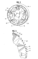
- This working portion 28 includes a series of circumferentially spaced teeth 30.
- these teeth 30 may be constructed of differing shapes.
- some teeth 32 may be "straight,” which means each tooth extends substantially in a radial orientation with straight edges 34 terminating at a point 36.
- Other teeth 38 may be "hooked,” which means they extend at an angle to the radius of the wheel with, for example, one straight edge 40 and a generally curved edge 41 terminating at an angled point 42.
- the center abrading wheel may have hooked teeth that are angled in opposite directions relative to the radius of the wheel, such as teeth 38' and 38", and also straight teeth 32.
- the teeth are arranged in sets around the circumference of the wheel 22, with one set comprising a series of hooked teeth 38', and another set comprising a series of hooked teeth 38", each inclined toward the other. These hooked teeth are flanked by sets of straight teeth 32.
- the straight teeth may also have a circumferential dimension somewhat less than that of the hooked teeth so that the density of straight teeth along the circumference of wheel 22 will be greater than the density of hooked teeth. This arrangement has been found to minimize any pattern that might form on the rubber surface being treated, resulting in a more uniform surface after the abrading process has been performed.
- each of the three wheels that make up the wheel assembly 20 is also fabricated so that their perimeters form a repeating and continuous wave, with the apex of each wave being displaced axially from the plane of the wheel center by about one-eighth to one-quarter inch (6.35mm). The apex of each wave is displaced to the side of the wheel's plane opposite to that of the adjacent apex.
- each apex is displaced about three-sixteenths inch (4.76mm) from the wheel center's plane.
- the number of apexes employed will depend upon the size of the wheel and the amplitude and the frequency of the wave-form. Between about eight and twenty apexes is the preferred range.
- the portion of the wheel's circumference between adjacent apexes may be termed a "segment" of the wheel.
- the sets of teeth mentioned above will be grouped, as shown in FIGURE 2, such that one set of hooked teeth 38' will occupy one segment, followed by a set of hooked teeth 38" on the next segment, and finally a set of straight teeth 32 on the next segment. This pattern is then repeated around the entire circumference of the wheel 22.
- each of the support wheels 24 conforms in shape to the form of the abrading wheel 22.
Landscapes
- Engineering & Computer Science (AREA)
- Mechanical Engineering (AREA)
- Moulds For Moulding Plastics Or The Like (AREA)
- Polishing Bodies And Polishing Tools (AREA)
- Heating, Cooling, Or Curing Plastics Or The Like In General (AREA)
- Tyre Moulding (AREA)
- Tires In General (AREA)
Applications Claiming Priority (2)
| Application Number | Priority Date | Filing Date | Title |
|---|---|---|---|
| US09/976,752 US6682272B2 (en) | 2001-10-12 | 2001-10-12 | Rubber cutting apparatus |
| US976752 | 2001-10-12 |
Publications (1)
| Publication Number | Publication Date |
|---|---|
| EP1306155A2 true EP1306155A2 (de) | 2003-05-02 |
Family
ID=25524423
Family Applications (1)
| Application Number | Title | Priority Date | Filing Date |
|---|---|---|---|
| EP20020394100 Withdrawn EP1306155A2 (de) | 2001-10-12 | 2002-10-11 | Gummiraspelvorrichtung |
Country Status (6)
| Country | Link |
|---|---|
| US (1) | US6682272B2 (de) |
| EP (1) | EP1306155A2 (de) |
| JP (1) | JP2003181792A (de) |
| BR (1) | BR0204106B1 (de) |
| CA (1) | CA2407822C (de) |
| TW (1) | TWI222393B (de) |
Families Citing this family (4)
| Publication number | Priority date | Publication date | Assignee | Title |
|---|---|---|---|---|
| AU2003255189B2 (en) * | 2003-10-21 | 2009-04-30 | Pincott International Pty Ltd | Rasp blade with non-planar teeth |
| CA2705732A1 (en) | 2007-11-13 | 2009-05-22 | Orthopediatrics, Llc | Cast removal system |
| US7972200B2 (en) * | 2007-12-21 | 2011-07-05 | B&J Rocket America, Inc. | Abrading wheel with sintered metal core |
| WO2017115327A1 (en) * | 2015-12-30 | 2017-07-06 | Elgi Rubber Company Ltd. | Tire rasp blade |
Family Cites Families (34)
| Publication number | Priority date | Publication date | Assignee | Title |
|---|---|---|---|---|
| US2703446A (en) | 1953-10-28 | 1955-03-08 | Emil B Jensen | Tire rasp |
| US2896309A (en) | 1957-07-05 | 1959-07-28 | Emil B Jensen | Tire rasp |
| US2975504A (en) | 1958-07-11 | 1961-03-21 | Bentham Frank Holdsworth | Rasping appliances and cutters |
| US3082506A (en) | 1959-04-29 | 1963-03-26 | Emil B Jensen | Tire rasp |
| US3102325A (en) | 1960-01-11 | 1963-09-03 | Alton E Tobey | Rasp blade construction |
| US3074148A (en) | 1960-01-11 | 1963-01-22 | Alton E Tobey | Rasp hub |
| US3351997A (en) | 1967-03-21 | 1967-11-14 | Neilsen Products Co | Toothed blade for tire rasp |
| US3618187A (en) | 1969-03-13 | 1971-11-09 | Wayne Emil Jensen | Tire peeling device |
| US3747177A (en) | 1969-03-13 | 1973-07-24 | W Jensen | Tire peeling device |
| AU442257B2 (en) | 1969-04-01 | 1973-11-05 | Kookaburra Retread Equipment Pty. Limited | Blades for rubber tyre rasps |
| US4263958A (en) | 1970-11-16 | 1981-04-28 | B & J Manufacturing Company | Tire mounting, bead seating and inflation apparatus and method of use |
| US3711909A (en) | 1970-12-14 | 1973-01-23 | Chromalloy American Corp | Tire rasp |
| US3742655A (en) | 1972-01-14 | 1973-07-03 | Oliver Inc L | Abrading wheel |
| US3869795A (en) * | 1973-06-20 | 1975-03-11 | Richards Mfg Co | Cutting blade for use with an oscillating cast cutter |
| US3879825A (en) | 1974-05-20 | 1975-04-29 | B & J Mfg Co | Tire buffing machine blades |
| US4059875A (en) | 1975-12-12 | 1977-11-29 | B & J Manufacturing Company | Tire rasp blades with renewable cutting and buffing edges |
| US4021899A (en) | 1975-12-12 | 1977-05-10 | B. & J. Manufacturing Company | Tire buffing machine blades having heat dissipation means |
| US4019234A (en) | 1976-05-03 | 1977-04-26 | B & J Manufacturing Company | Tire rasp having reversible blade holder assemblies |
| US4091516A (en) | 1977-05-10 | 1978-05-30 | B. & J. Manufacturing Company | Tire rasp blade having multi-cutting edges |
| ATA708379A (de) | 1979-11-05 | 1981-12-15 | Miba Sintermetall Ag | Klinge fuer ein zylindrisches drehwerkzeug zum spannabhebenden bearbeiten von fahrzeugluftreifen |
| US4283820A (en) | 1979-11-14 | 1981-08-18 | Miba Sintermetall Aktiengesellschaft | Segment-shaped blade |
| US4283819A (en) | 1979-11-14 | 1981-08-18 | Miba Sintermetall Aktiengesellschaft | Segment-shaped blade |
| US4287648A (en) | 1980-03-24 | 1981-09-08 | Amf Incorporated | Tire buffing blade |
| US4747194A (en) | 1985-10-02 | 1988-05-31 | Spencer Industries Pty. Ltd. | Tire rasp blade |
| US4843768A (en) | 1986-12-01 | 1989-07-04 | B & J Manufacturing Company | Abrading apparatus and process for making the same |
| US5054177A (en) | 1988-03-10 | 1991-10-08 | B & J Manufacturing Company | Tire rasp blade |
| US5075942A (en) | 1988-03-10 | 1991-12-31 | B & J Manufacturing Company | Tire rasp blade |
| US5033175A (en) | 1990-02-21 | 1991-07-23 | B & J Manufacturing Company | Tire rasp blade |
| US5239784A (en) | 1990-04-18 | 1993-08-31 | B & J Manufacturing Company | Cavitied abrading device with smooth lands area and layered grit |
| US5170593A (en) | 1991-03-18 | 1992-12-15 | Jason, Inc. | Method of making a perforated strip abrasive tool |
| US5791330A (en) | 1991-06-10 | 1998-08-11 | Ultimate Abrasive Systems, L.L.C. | Abrasive cutting tool |
| US5303688A (en) * | 1992-04-03 | 1994-04-19 | Chiuminatta Edward R | Mounting arbor for saw cutting blades |
| US5504981A (en) | 1993-08-20 | 1996-04-09 | B & J Manufacturing Company | Bent blade and spacer tire rasp hub assembly |
| US5461762A (en) | 1993-08-31 | 1995-10-31 | B & J Manufacturing Co. | Compound elliptical tire rasp blade |
-
2001
- 2001-10-12 US US09/976,752 patent/US6682272B2/en not_active Expired - Lifetime
-
2002
- 2002-02-01 TW TW91101837A patent/TWI222393B/zh active
- 2002-10-09 JP JP2002295869A patent/JP2003181792A/ja active Pending
- 2002-10-10 BR BRPI0204106-5A patent/BR0204106B1/pt not_active IP Right Cessation
- 2002-10-11 EP EP20020394100 patent/EP1306155A2/de not_active Withdrawn
- 2002-10-11 CA CA 2407822 patent/CA2407822C/en not_active Expired - Fee Related
Also Published As
| Publication number | Publication date |
|---|---|
| BR0204106A (pt) | 2003-09-16 |
| US6682272B2 (en) | 2004-01-27 |
| TWI222393B (en) | 2004-10-21 |
| CA2407822C (en) | 2010-09-21 |
| JP2003181792A (ja) | 2003-07-02 |
| US20030072623A1 (en) | 2003-04-17 |
| CA2407822A1 (en) | 2003-04-12 |
| BR0204106B1 (pt) | 2011-04-05 |
Similar Documents
| Publication | Publication Date | Title |
|---|---|---|
| TW348095B (en) | Electrodeposited diamond wheel | |
| AU628523B2 (en) | Tire rasp blade | |
| EP1306155A2 (de) | Gummiraspelvorrichtung | |
| US4685181A (en) | Heavy duty rotary disc rasp | |
| US5125192A (en) | Flexible sanding/deburring head | |
| EP0640423B1 (de) | Ein Reifenraspelblatt | |
| EP0270333A2 (de) | Schleifgerät und Verfahren zum Herstellen desselben | |
| EP0639419B1 (de) | Eine Nabe für Raspelsatz | |
| JP2006501074A (ja) | ナイフの刃の縁部を研磨するための工具 | |
| GB2207626A (en) | Abrasive polishing element | |
| AU2003255189B2 (en) | Rasp blade with non-planar teeth | |
| JP3034101U (ja) | 回転刃及び回転工具 | |
| US6695547B2 (en) | Tire rasp blade and assembly | |
| SU1691086A1 (ru) | Абразивный инструмент | |
| US4651477A (en) | Wheel assembly for an abrasive blasting apparatus | |
| US7827662B2 (en) | Device of a descaler head | |
| AU719185B3 (en) | Tyre rasp blade and assembly | |
| JP3738571B2 (ja) | ローディングカム装置のカム面の加工方法及び加工装置 | |
| HK1013970B (en) | A tire rasp blade | |
| AU736898B2 (en) | Tyre rasp blade and assembly | |
| KR200243375Y1 (ko) | 절단숫돌휠 | |
| EP1741508A1 (de) | Kreissägeblatt | |
| JP2001009683A (ja) | 刃面研削工具 | |
| HK1013971B (en) | A rasp hub assembly |
Legal Events
| Date | Code | Title | Description |
|---|---|---|---|
| PUAI | Public reference made under article 153(3) epc to a published international application that has entered the european phase |
Free format text: ORIGINAL CODE: 0009012 |
|
| AK | Designated contracting states |
Designated state(s): AT BE BG CH CY CZ DE DK EE ES FI FR GB GR IE IT LI LU MC NL PT SE SK TR |
|
| AX | Request for extension of the european patent |
Extension state: AL LT LV MK RO SI |
|
| STAA | Information on the status of an ep patent application or granted ep patent |
Free format text: STATUS: THE APPLICATION IS DEEMED TO BE WITHDRAWN |
|
| 18D | Application deemed to be withdrawn |
Effective date: 20070501 |