EP1306000B1 - Method for optimizing the harvesting of high-quality forage - Google Patents
Method for optimizing the harvesting of high-quality forage Download PDFInfo
- Publication number
- EP1306000B1 EP1306000B1 EP02019329A EP02019329A EP1306000B1 EP 1306000 B1 EP1306000 B1 EP 1306000B1 EP 02019329 A EP02019329 A EP 02019329A EP 02019329 A EP02019329 A EP 02019329A EP 1306000 B1 EP1306000 B1 EP 1306000B1
- Authority
- EP
- European Patent Office
- Prior art keywords
- mower
- swath
- working
- strip
- front mower
- Prior art date
- Legal status (The legal status is an assumption and is not a legal conclusion. Google has not performed a legal analysis and makes no representation as to the accuracy of the status listed.)
- Expired - Lifetime
Links
- 238000000034 method Methods 0.000 title claims abstract description 14
- 238000003306 harvesting Methods 0.000 title claims 5
- 239000004459 forage Substances 0.000 title 1
- 238000004519 manufacturing process Methods 0.000 claims description 3
- 230000002441 reversible effect Effects 0.000 claims description 2
- 238000000151 deposition Methods 0.000 claims 1
- 239000004460 silage Substances 0.000 abstract 5
- 230000015572 biosynthetic process Effects 0.000 description 3
- 238000011109 contamination Methods 0.000 description 2
- 239000002689 soil Substances 0.000 description 2
- 238000006243 chemical reaction Methods 0.000 description 1
- 238000009826 distribution Methods 0.000 description 1
- 230000000694 effects Effects 0.000 description 1
- 235000021050 feed intake Nutrition 0.000 description 1
- 238000003754 machining Methods 0.000 description 1
- 238000003860 storage Methods 0.000 description 1
- 230000032258 transport Effects 0.000 description 1
Images

Classifications
-
- A—HUMAN NECESSITIES
- A01—AGRICULTURE; FORESTRY; ANIMAL HUSBANDRY; HUNTING; TRAPPING; FISHING
- A01D—HARVESTING; MOWING
- A01D43/00—Mowers combined with apparatus performing additional operations while mowing
- A01D43/06—Mowers combined with apparatus performing additional operations while mowing with means for collecting, gathering or loading mown material
- A01D43/077—Mowers combined with apparatus performing additional operations while mowing with means for collecting, gathering or loading mown material with auxiliary means, e.g. fans, for transporting the mown crop
-
- A—HUMAN NECESSITIES
- A01—AGRICULTURE; FORESTRY; ANIMAL HUSBANDRY; HUNTING; TRAPPING; FISHING
- A01D—HARVESTING; MOWING
- A01D57/00—Delivering mechanisms for harvesters or mowers
-
- A—HUMAN NECESSITIES
- A01—AGRICULTURE; FORESTRY; ANIMAL HUSBANDRY; HUNTING; TRAPPING; FISHING
- A01D—HARVESTING; MOWING
- A01D57/00—Delivering mechanisms for harvesters or mowers
- A01D57/20—Delivering mechanisms for harvesters or mowers with conveyor belts
Definitions
- the invention relates to a method for optimizing the production of high-quality feed according to the preamble of claim 1.
- a mowing unit is coupled to the front of a tractor, the other two are arranged on the sides of the tractor.
- the crop of the front mower is conveyed between the wheels.
- the two side mowers each feed the crop toward the vehicle to form a large swath limited in height by the clearance between the wheels and the distance between the highest point of the ground surface and the lowest point of the underside of the vehicle.
- CA 1183355 Another system for generating large swath by a self-propelled rake is disclosed in CA 1183355.
- the described three-piece rake sets the crop of the front mower directly next to the outside of a wheel.
- the swath close lateral mowing unit promotes the good on these swaths.
- the swathing mowing unit transports the crop below the tractor to the other windrows.
- Such a design causes unnecessary contamination of the underside of the machine, which can lead to increased downtime and downtime.
- arise in the swathing next to the wheels difficulties when cornering and in the headlands since the wheels of the tractor must drive over the deposited swaths. This inevitably leads to a greatly increased feed contamination.
- rear wheels are sometimes with smaller width and smaller Diameter selected for the tractor, but this leads to significant structural damage of the processed soils.
- the invention is therefore based on the object to develop a swath-storage system that generates cost-effective and reliable as possible clean large swaths with the greatest possible protection of both the Schwadablegenden machine and the subsequent Schwadaufenseden machine and the soil.
- the swath of the at least one front mower is combined with the swath of the at least one side mower and only when the neighboring second strip is processed, is the large swath created by the laying down of the swath of the at least one side mower Generating large swaths without having to feed through under the machine.
- the disadvantages described at the beginning of the feed pollution and the irregularly shaped wind are avoided.
- the mower blade drive of the at least one right or left side mower has a device that automatically switches off the mower blade drive when lifting the right or left side mower. By such a device, the risks can be minimized by solving mower blades for the direct environment.
- the at least one right side mower may be excavated during operation of the at least one left side mower and the at least one front mower and / or the at least one left side mower during operation of the at least one right side mower and the at least one front mower.
- the edge strip side mower By digging in particular the edge strip side mower can be mowed in very good visibility for the driver with the at least one front mower and the at least one oriented to the middle of the field mower, the associated windrows are merged without a small swath remains on the edge strip.
- the conveyors of the at least one front mower when processing a first processing strip store the crop outside the expected lane, the swath of the front mower is merged with the swath of at least one right or left side mower and in the processing of the adjacent second processing strip of the windrows of the front mower is stored outside the expected lane, wherein the windrow of the front mower is merged with the swath of the at least one left or right mower, while the swath of at least one right or left mower with the swath of the first processing strip is merged.
- the discharge direction of the conveyors of the mowers is reversible, so that a processing of adjacent strips in the opposite direction of travel is possible at the same volume of large swath.
- the pre-selectable routine control for the headland includes first raising the at least one front mower and then the left and right side mowers, and thereafter or during which the working direction of the conveyor of the front mower or conveyors of the front mower groups is reversed.
- the pre-selectable routine for the headland also includes that after or during the reversal of the working direction of the front mower conveyor or conveyors of the front mower groups the previously raised front mower or mower groups and then the previously raised right and left side mowers are lowered ,
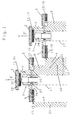
- FIG. 1 a multi-part mower (1) is shown, which consists of a front mower and a right and a left side mower (3, 4).
- This mower (1) mows successively at least two adjacent processing strips (5, 6) in the parallel direction.
- the swaths (7) of the front mower (2) are deposited in this embodiment with the windrows (8) of the right somumblewerks (3) right next to the expected lane (17), while the swaths (9) of the left somumblemaschines (4) the multi-part mower (1) is conveyed outwardly so that this swath (9) of the second processing strip (6) respectively to the merged swaths (7 and 8) of the front mower (2) and the right somumblewerks (3) of the first processing strip (5) to a large swath (10) are merged.
- the conveyors of the front mower and the side mowers (11, 12, 13) are formed in this example as cross conveyor belts (14, 15, 16).
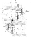
- FIG. 2 a multi-part mower (1) is shown, which mows successively at least two adjacent processing strips (5, 6) in the opposite direction.
- the conveying directions of all conveyors (11, 12, 13) for the crop (21) opposite to the conveying directions in the processing of the first strip (5) must be selected to form large swaths (10) when processing the second strip (6) become.
- the direction reversal of all conveyors (11, 12, 13) is preferably effected by a routine control (19), in which, for example, an electromagnetic signal (23) towards the drives (24, 25, 26) for the cross conveyor belts (14, 15, 16 ) change their direction of rotation.
- a preferably electromagnetic signal (23) out in the headland control first the front mower (2) and then the side mowers (3, 4) raised, then the direction of rotation of the cross conveyor belts (14, 15, 16) is reversed, then the front mower ( 2) and shortly after the side mowers (3, 4) lowered again.
- FIG. 3 a multi-part mower (1) is shown, which successively processed two strips (5, 6) with unidirectional working direction.
- the first strip (5) is an edge strip.
- the left side mower (4) is pivoted to work the edge strip (5) about the axis (27) to a non-working position.
- the drive for the mowing blades (18) is switched off automatically.
Landscapes
- Life Sciences & Earth Sciences (AREA)
- Environmental Sciences (AREA)
- Harvester Elements (AREA)
- Organic Low-Molecular-Weight Compounds And Preparation Thereof (AREA)
- Crystals, And After-Treatments Of Crystals (AREA)
Abstract
Description
Die Erfindung betrifft ein Verfahren zur Optimierung der Erzeugung von qualitativ hochwertigem Futter gemäß dem Oberbegriff des Anspruches 1.The invention relates to a method for optimizing the production of high-quality feed according to the preamble of
In dem deutschen Gebrauchsmuster
Ein weiteres System zur Erzeugung eines Großschwadens durch einen selbstfahrenden Schwader wird in der CA 1183355 offenbart. Der beschriebene dreiteilige Schwader legt das Erntegut des Frontmähwerkes direkt neben der Außenseite eines Rades ab. Die schwadnahe seitliche Mäheinheit fördert das Gut auf diesen Schwaden zu. Die schwadferne Mäheinheit transportiert das Erntegut unterhalb des Schleppers zu den anderen Schwaden. Durch eine solche Konstruktion wird eine unnötige Verschmutzung der Unterseite der Maschine verursacht, die zu erhöhten Ausfall- und Stillstandszeiten führen kann. Zudem entstehen bei der Schwadablage neben den Rädern Schwierigkeiten bei Kurvenfahrten und im Vorgewende, da die Räder des Schleppers über den abgelegten Schwaden fahren müssen. Das führt zwangsläufig zu einer stark erhöhten Futterverschmutzung. Um diesen Nachteil zu vermeiden, werden mitunter Hinterräder mit geringerer Breite und kleinerem Durchmesser für den Schlepper gewählt, was allerdings zu erheblichen Strukturschäden der bearbeiteten Böden führt.Another system for generating large swath by a self-propelled rake is disclosed in CA 1183355. The described three-piece rake sets the crop of the front mower directly next to the outside of a wheel. The swath close lateral mowing unit promotes the good on these swaths. The swathing mowing unit transports the crop below the tractor to the other windrows. Such a design causes unnecessary contamination of the underside of the machine, which can lead to increased downtime and downtime. In addition, arise in the swathing next to the wheels difficulties when cornering and in the headlands, since the wheels of the tractor must drive over the deposited swaths. This inevitably leads to a greatly increased feed contamination. In order to avoid this disadvantage, rear wheels are sometimes with smaller width and smaller Diameter selected for the tractor, but this leads to significant structural damage of the processed soils.
Der Erfindung liegt daher die Aufgabe zugrunde, ein Schwadablagesystem zu entwickeln, das unter größtmöglicher Schonung sowohl der schwadablegenden Maschine als auch der nachfolgenden schwadaufnehmenden Maschine und des Bodens kostengünstig und zuverlässig möglichst saubere Großschwaden erzeugt.The invention is therefore based on the object to develop a swath-storage system that generates cost-effective and reliable as possible clean large swaths with the greatest possible protection of both the Schwadablegenden machine and the subsequent Schwadaufnehmenden machine and the soil.
Erfindungsgemäß wird die Aufgabe durch ein Verfahren mit den kennzeichnenden Merkmalen des Anspruches 1 gelöst.According to the invention the object is achieved by a method having the characterizing features of
Dadurch, dass bei der Bearbeitung des ersten Streifens der Schwaden des wenigstens einen Frontmähwerks mit dem Schwaden des mindestens einen Seitenmähwerks zusammengelegt wird und erst bei der Bearbeitung des benachbarten zweiten Streifens der Großschwaden durch das Hinzulegen des Schwadens des mindestens einen Seitenmähwerks entsteht, gelingt es, einen Großschwaden zu erzeugen, ohne unter der Maschine hindurchfördern zu müssen. Dadurch werden insbesondere die eingangsbeschriebenen Nachteile der Futterverschmutzung und des ungleichmäßig geformten Schwadens vermieden.Due to the fact that during the processing of the first strip, the swath of the at least one front mower is combined with the swath of the at least one side mower and only when the neighboring second strip is processed, is the large swath created by the laying down of the swath of the at least one side mower Generating large swaths without having to feed through under the machine. As a result, in particular the disadvantages described at the beginning of the feed pollution and the irregularly shaped wind are avoided.
Der Mähmesserantrieb des wenigstens einen rechten bzw. linken Seitenmähwerks verfügt über eine Einrichtung, die beim Ausheben des rechten bzw. linken Seitenmähwerks den Mähmesserantrieb selbsttätig abschaltet. Durch eine derartige Einrichtung können die Gefährdungen durch sich lösende Mähmesser für die direkte Umgebung minimiert werden.The mower blade drive of the at least one right or left side mower has a device that automatically switches off the mower blade drive when lifting the right or left side mower. By such a device, the risks can be minimized by solving mower blades for the direct environment.
Das wenigstens eine rechte Seitenmähwerk kann während der Arbeit des mindestens einen linken Seitenmähwerks und des wenigstens einen Frontmähwerks und/oder das wenigstens eine linke Seitenmähwerk während der Arbeit des mindestens einen rechten Seitenmähwerks und des wenigstens einen Frontmähwerks ausgehoben werden. Durch das Ausheben insbesondere der randstreifenseitigen Seitenmähwerke kann bei sehr guten Sichtverhältnissen für den Fahrer mit dem wenigstens einen Frontmähwerk und dem wenigstens einen zur Feldmitte orientierten Seitenmähwerk gemäht werden, wobei die zugehörigen Schwaden zusammengelegt werden, ohne dass ein kleiner Schwaden am Randstreifen zurückbleibt.The at least one right side mower may be excavated during operation of the at least one left side mower and the at least one front mower and / or the at least one left side mower during operation of the at least one right side mower and the at least one front mower. By digging in particular the edge strip side mower can be mowed in very good visibility for the driver with the at least one front mower and the at least one oriented to the middle of the field mower, the associated windrows are merged without a small swath remains on the edge strip.
In besonders vorteilhafter Weise können die Fördereinrichtungen des wenigstens einen Frontmähwerks bei der Bearbeitung eines ersten Bearbeitungsstreifens das Erntegut außerhalb der zu erwartenden Fahrspur ablegen, wobei der Schwaden des Frontmähwerks mit dem Schwaden des wenigstens einen rechten bzw. linken Seitenmähwerks zusammengelegt wird und bei der Bearbeitung des angrenzenden zweiten Bearbeitungsstreifens der Schwaden des Frontmähwerkes außerhalb der zu erwartenden Fahrspur abgelegt wird, wobei der Schwaden des Frontmähwerks mit dem Schwaden des wenigstens einen linken bzw. rechten Mähwerks zusammengelegt wird, während der Schwaden des mindestens einen rechten bzw. linken Mähwerks mit dem Schwaden des ersten Bearbeitungsstreifens zusammengelegt wird. Dadurch ist es möglich, die benachbarten Streifen auch in entgegengesetzter Fahrtrichtung zu bearbeiten.In a particularly advantageous manner, the conveyors of the at least one front mower when processing a first processing strip store the crop outside the expected lane, the swath of the front mower is merged with the swath of at least one right or left side mower and in the processing of the adjacent second processing strip of the windrows of the front mower is stored outside the expected lane, wherein the windrow of the front mower is merged with the swath of the at least one left or right mower, while the swath of at least one right or left mower with the swath of the first processing strip is merged. This makes it possible to edit the adjacent strips in the opposite direction.
In einer besonders vorteilhaften Ausführungsform ist die Austragsrichtung der Fördereinrichtungen der Mähwerke umkehrbar, so dass auch eine Bearbeitung von benachbarten Streifen in entgegengesetzter Fahrtrichtung bei gleichbleibendem Volumen des Großschwadens möglich ist. Auf eine derartige Änderung der Austragsrichtungen der Fördereinrichtung kann durch die konsequente Beibehaltung der Bearbeitungsrichtung auf den benachbarten Bearbeitungsstreifen jedoch auch verzichtet werden.In a particularly advantageous embodiment, the discharge direction of the conveyors of the mowers is reversible, so that a processing of adjacent strips in the opposite direction of travel is possible at the same volume of large swath. However, it is also possible to dispense with such a change in the discharge directions of the conveying device by consistently maintaining the machining direction on the adjacent processing strips.
In einer weiteren erfindungsgemäßen Ausführungsform existiert eine vorwählbare Routinesteuerung für das Vorgewende, die zumindest eine Teilautomatisierung der komplexen Tätigkeiten zur Umstellung der Maschine auf einen Streifen, der in entgegengesetzter Fahrtrichtung bearbeitet werden soll, und somit eine Richtungsumkehr aller Querfördereinrichtungen erfordert, bewirkt. In einer vorteilhaften Ausführungsform beinhaltet die vorwählbare Routinesteuerung für das Vorgewende, dass erst das wenigstens eine Frontmähwerk und dann die linken und rechten Seitenmähwerke angehoben werden, und danach oder währenddessen die Arbeitsrichtung der Fördereinrichtung des Frontmähwerks bzw. der Fördereinrichtungen der Frontmähwerksgruppen umgekehrt wird. Weiterhin ist es von Vorteil, wenn die vorwählbare Routinesteuerung für das Vorgewende auch beinhaltet, dass nach oder während der Umkehrung der Arbeitsrichtung der Fördereinrichtung des Frontmähwerks bzw. der Fördereinrichtungen der Frontmähwerksgruppen das zuvor angehobene Frontmähwerk bzw. die Frontmähwerksgruppen und danach die zuvor angehobenen rechten und linken Seitenmähwerke abgesenkt werden.In a further embodiment of the invention there is a pre-selectable routine control for the headland, which causes at least partial automation of the complex activities for the conversion of the machine to a strip which is to be processed in the opposite direction, and thus reversing the direction of all cross conveyors causes. In an advantageous embodiment, the pre-selectable routine control for the headland includes first raising the at least one front mower and then the left and right side mowers, and thereafter or during which the working direction of the conveyor of the front mower or conveyors of the front mower groups is reversed. It continues advantageous if the pre-selectable routine for the headland also includes that after or during the reversal of the working direction of the front mower conveyor or conveyors of the front mower groups the previously raised front mower or mower groups and then the previously raised right and left side mowers are lowered ,
Das erfindungsgemäße Verfahren wird nachfolgend anhand von in Zeichnungen dargestellten Ausführungsbeispielen näher erläutert.The inventive method will be explained in more detail with reference to embodiments shown in the drawings.
Es zeigen
Figur 1- die erfindungsgemäße Bildung von Großschwaden durch ein mehrteiliges Mähwerk bei zwei Streifen mit gleichgerichteter Bearbeitungsrichtung
Figur 2- die erfindungsgemäße Bildung von Großschwaden durch ein mehrteiliges Mähwerk bei zwei Streifen mit entgegengesetzter Bearbeitungsrichtung
- Figur 3
- die erfindungsgemäße Bildung von Großschwaden durch ein mehrteiliges Mähwerk bei zwei Streifen mit gleichgerichteter Bearbeitungsrichtung, wobei es sich bei einem Streifen um einen Randstreifen handelt
- FIG. 1
- the inventive formation of large swaths by a multi-part mower with two strips with the same direction of processing
- FIG. 2
- the inventive formation of large swaths by a multi-part mower with two strips with opposite processing direction
- FIG. 3
- the formation of large swaths according to the invention by a multi-part mower in two strips with the same direction processing direction, wherein it is a strip at an edge strip
In
In
In
- 11
- MähwerkMower
- 22
- FrontmähwerkFrontmähwerk
- 33
- rechtes Seitenmähwerkright side mower
- 44
- linkes Seitenmähwerkleft side mower
- 55
- erster Bearbeitungsstreifenfirst processing strip
- 66
- zweiter Bearbeitungsstreifensecond processing strip
- 77
- Schwaden des FrontmähwerksSwath of the front mower
- 88th
- Schwaden des rechten SeitenmähwerksSwathing of the right side mower
- 99
- Schwaden des linken SeitenmähwerksSwathing of the left side mower
- 1010
- Großschwadenlarge swaths
- 1111
- Fördereinrichtung des FrontmähwerksConveyor of the front mower
- 1212
- Fördereinrichtung des rechten SeitenmähwerksConveyor of the right side mower
- 1313
- Fördereinrichtung des linken SeitenmähwerksConveyor of the left side mower
- 1414
- Querförderband des FrontmähwerksCross conveyor of the front mower
- 1515
- Querförderband des rechten SeitenmähwerksCross conveyor of the right side mower
- 1616
- Querförderband des linken SeitenmähwerksCross conveyor of the left side mower
- 1717
- Fahrspurlane
- 1818
- Mähmesserantriebblades from rotating
- 1919
- Routinesteuerungroutine control
- 2020
- Vorgewendeheadland
- 2121
- Erntegutcrop
- 2222
- Schwaden des ersten BearbeitungsstreifensSwathing of the first processing strip
- 2323
- elektromagnetisches Signalelectromagnetic signal
- 2424
- Antriebdrive
- 2525
- Antriebdrive
- 2626
- Antriebdrive
- 2727
- Achseaxis
- FF
- Fahrtrichtungdirection of travel
Claims (10)
- Method for producing large swathes on an agricultural area with at least one first and one second working strip by means of a multipart self-propelled mower consisting of at least one front mower (2), at least one right side mower and at least one left side mower (3, 4), the individual mowers (2, 3, 4) of which are assigned conveying devices, which convey the harvest substantially at right angles to the travelling direction of the self-propelled mower, characterised in that when working the first working strip (5) the swath (7) of the at least one front mower (2) is laid together with the swath (8, 9) of at least one side mower (3, 4) and only when working the adjacent second working strip (6) is the large swath (10) formed by adding at least one further swath (8, 9) of at least one side mower (3, 4), and in that the mowing blade drive (18) of the at least one right or left side mower (3, 4) switches off automatically on retracting the right or left side mower (3, 4), and in that the at least one right side mower (3) can be retracted when working the at least one left side mower (4) and the at least one front mower (2) or In that the at least one left side mower (4) can be retracted when working the at least one right side mower (3) and the at least one front mower (2).
- Method according to claim 1, characterised in that the conveying device (11) of the at least one front mower (2) when working a first working strip (5) lays down the harvest (21) outside the expected driving track (17), whereby the swath (7) of the front mower (2) is placed down together with the swath (8) of the at least one right side mower (3) and when working the adjoining second working strip (6) the swath (7) of the front mower (2) is laid down outside the expected driving track (17), whereby the swath (7) of the front mower (2) is placed together with the swath (9) of the at least one left mower (4), whereas the swath (8) of the at least one right mower (3) is placed together with the swath (22) of the first working strip (5).
- Method according to claim 1, characterised in that the conveying device (11) of the at least one front mower (2) when working a first working strip (5) lays down the harvest (21) outside the expected driving track (17), whereby the swath (7) of the front mower (2) is placed down together with the swath (9) of the at least one left side mower (4) and when working the adjacent second working strip (6) the swath (7) of the front mower (2) is placed down outside the expected driving track (17), whereby the swath (7) of the front mower (2) is placed together with the swath (8) of the at least one right mower (3), whereas the swath (9) of the at least one left mower (4) is placed together with swath (22) of the first working strip (5).
- Method according to one or more of the preceding claims, characterised in that the discharge direction of the conveying devices (11, 12, 13) Is reversible.
- Method according to one or more of the preceding claims, characterised in that with the same travelling direction on adjacent working strips (5, 6) there is no change in the discharge direction of the conveying devices (11, 12, 13).
- Method according to one or more of the preceding claims, characterised in that with an opposite travelling direction on adjacent working strips (5, 6) the discharge direction of the conveying devices (11, 12, 13) is reversed.
- Method according to one or more of the preceding claims, characterised in that there is a preselectable routine control (19) for the turning area (20).
- Method according to claim 7, characterised in that the preselectable routine control (19) for the turning area (20) includes lifting the at least one front mower (2) and then the left and right side mowers (3, 4) and after this or during this the working direction of the conveying device (11) of the front mower (2) or the conveying devices (11) of the front mower groups (2) is reversed.
- Method according to one or more of the preceding claims 7 and 8, characterised in that the preselectable routine control (19) for the turning area (20) Includes, after or during the reversal of the operating direction of the conveying device (11) of the front mower (2) or the conveying devices (11) of the front mower groups (2), lowering the previously lifted front mower (2) or the front mower groups (2) and afterwards the previously lifted right and left side mowers (3, 4).
- Method for producing large swathes on an agricultural area with at least one first and one second working strip with a multipart self-propelled mower consisting of at least one front mower, at least one right side mower and at least one left side mower, the individual mowers of which are assigned conveying devices, which convey the harvest substantially at right angles to the travelling direction of the self-propelled mower, characterised in that the conveying device of at least one side mower comprises a conveying device towards the outside, in order to allow the depositing of swaths on the outside of the side mower, in that the mowing blade drive (18) of the at least one right or left side mower (3, 4) comprises a device, which automatically switches off the mower blade drive (18) on retracting the right or left side mower (3, 4), and in that means are provided, so that the at least one right side mower (3) can be retracted during the operation of the at least one left side mower (4) and the at least one front mower (2), or so that the at least one left side mower (4) can be retracted during the operation of the at least one right side mower (3) and the at least one front mower (2).
Priority Applications (1)
| Application Number | Priority Date | Filing Date | Title |
|---|---|---|---|
| EP06020235A EP1743514A1 (en) | 2001-10-23 | 2002-08-29 | Mowing device with a plurality of mowers, at least one in the front, one at the left and one at the right side |
Applications Claiming Priority (2)
| Application Number | Priority Date | Filing Date | Title |
|---|---|---|---|
| DE10151571 | 2001-10-23 | ||
| DE10151571A DE10151571A1 (en) | 2001-10-23 | 2001-10-23 | Process for optimizing the production of high quality feed |
Related Child Applications (1)
| Application Number | Title | Priority Date | Filing Date |
|---|---|---|---|
| EP06020235A Division EP1743514A1 (en) | 2001-10-23 | 2002-08-29 | Mowing device with a plurality of mowers, at least one in the front, one at the left and one at the right side |
Publications (2)
| Publication Number | Publication Date |
|---|---|
| EP1306000A1 EP1306000A1 (en) | 2003-05-02 |
| EP1306000B1 true EP1306000B1 (en) | 2009-03-25 |
Family
ID=7702999
Family Applications (2)
| Application Number | Title | Priority Date | Filing Date |
|---|---|---|---|
| EP06020235A Withdrawn EP1743514A1 (en) | 2001-10-23 | 2002-08-29 | Mowing device with a plurality of mowers, at least one in the front, one at the left and one at the right side |
| EP02019329A Expired - Lifetime EP1306000B1 (en) | 2001-10-23 | 2002-08-29 | Method for optimizing the harvesting of high-quality forage |
Family Applications Before (1)
| Application Number | Title | Priority Date | Filing Date |
|---|---|---|---|
| EP06020235A Withdrawn EP1743514A1 (en) | 2001-10-23 | 2002-08-29 | Mowing device with a plurality of mowers, at least one in the front, one at the left and one at the right side |
Country Status (3)
| Country | Link |
|---|---|
| EP (2) | EP1743514A1 (en) |
| AT (1) | ATE426326T1 (en) |
| DE (2) | DE10151571A1 (en) |
Cited By (1)
| Publication number | Priority date | Publication date | Assignee | Title |
|---|---|---|---|---|
| US8074432B2 (en) | 2002-03-21 | 2011-12-13 | Kuhn S.A. | Agricultural mower comprising a carrying vehicle and several work units |
Families Citing this family (7)
| Publication number | Priority date | Publication date | Assignee | Title |
|---|---|---|---|---|
| DE10234302A1 (en) | 2002-07-26 | 2004-02-05 | Claas Saulgau Gmbh | Method and device for producing high quality feed |
| DE102008058281A1 (en) | 2008-11-20 | 2010-05-27 | Alois Pöttinger Maschinenfabrik Gmbh | Mower and method for creating ravages when mowing a field |
| NL1037815C2 (en) * | 2010-03-18 | 2011-09-20 | Forage Innovations Bv | HAY BUILDING DEVICE. |
| DE102015002236A1 (en) * | 2015-02-20 | 2016-08-25 | Alois Pöttinger Maschinenfabrik Ges.m.b.H. | Hay-making machine |
| US10542674B2 (en) * | 2017-05-19 | 2020-01-28 | Cnh Industrial America Llc | Methods for creating merged triple windrows |
| GB201918843D0 (en) | 2019-12-19 | 2020-02-05 | Agco Int Gmbh | Mower combination |
| GB201918841D0 (en) * | 2019-12-19 | 2020-02-05 | Agco Int Gmbh | Mower combination |
Family Cites Families (11)
| Publication number | Priority date | Publication date | Assignee | Title |
|---|---|---|---|---|
| US3343347A (en) * | 1965-03-17 | 1967-09-26 | Deere & Co | Windrower type harvester |
| US3731469A (en) * | 1972-01-24 | 1973-05-08 | Jacobsen Mfg Co | Convertible gang lawn mower |
| CA1269848A (en) * | 1986-04-30 | 1990-06-05 | William T. Arnold | Grass collection system for mower |
| DK171218B1 (en) * | 1992-02-28 | 1996-08-05 | Freudendahl J Fab As | Lawn mower mower |
| DK170692B1 (en) * | 1993-03-08 | 1995-12-11 | Freudendahl J Fab As | Mower for harvesting grass crops with two side-by-side mowers |
| DE4409113C1 (en) * | 1994-03-17 | 1995-09-07 | Fortschritt Erntemaschinen | Steered work unit combination on front-steered support vehicle |
| DE29719765U1 (en) | 1997-11-07 | 1998-12-17 | Maschinenfabrik Bernard Krone GmbH, 48480 Spelle | Suspension for work units attached to both sides of a carrier vehicle |
| DE19804250A1 (en) * | 1998-02-04 | 1999-08-05 | Deere & Co | Swathing device |
| US6205757B1 (en) * | 1999-02-19 | 2001-03-27 | Byron Enterprises, Inc. | Windrow merging machine and method of merging windrows |
| DE19932285A1 (en) * | 1999-07-10 | 2001-04-26 | Deere & Co | Self-propelled mower and conveyor |
| DE10121014A1 (en) * | 2001-04-28 | 2002-11-21 | Deere & Co | mowing |
-
2001
- 2001-10-23 DE DE10151571A patent/DE10151571A1/en not_active Withdrawn
-
2002
- 2002-08-29 EP EP06020235A patent/EP1743514A1/en not_active Withdrawn
- 2002-08-29 DE DE50213384T patent/DE50213384D1/en not_active Expired - Lifetime
- 2002-08-29 EP EP02019329A patent/EP1306000B1/en not_active Expired - Lifetime
- 2002-08-29 AT AT02019329T patent/ATE426326T1/en not_active IP Right Cessation
Cited By (3)
| Publication number | Priority date | Publication date | Assignee | Title |
|---|---|---|---|---|
| US8074432B2 (en) | 2002-03-21 | 2011-12-13 | Kuhn S.A. | Agricultural mower comprising a carrying vehicle and several work units |
| US8220233B2 (en) | 2002-03-21 | 2012-07-17 | Kuhn S.A. | Agricultural mower comprising a carrying vehicle with four steering and driving wheels and plural pivotable front and lateral work units |
| US8225588B2 (en) | 2002-03-21 | 2012-07-24 | Kuhn S.A. | Agricultural mower comprising a carrying vehicle with plural pivotable front and lateral work units and a height adjustable front hitching device |
Also Published As
| Publication number | Publication date |
|---|---|
| ATE426326T1 (en) | 2009-04-15 |
| DE50213384D1 (en) | 2009-05-07 |
| EP1743514A1 (en) | 2007-01-17 |
| DE10151571A1 (en) | 2003-04-30 |
| EP1306000A1 (en) | 2003-05-02 |
Similar Documents
| Publication | Publication Date | Title |
|---|---|---|
| EP1106051B1 (en) | Mower | |
| DE1582294C3 (en) | ||
| EP2067397B1 (en) | Harvester head to gather and transport cereals in an agricultural harvesting machine | |
| EP1932416B1 (en) | Device comprising a first and a second work unit | |
| EP1281312B1 (en) | Device with a pick-up, a conveyor and connecting means with a vehicle | |
| EP1010363B1 (en) | Machine for mowing and chopping maize and such stalk crops | |
| EP0891693B1 (en) | Disc cutter bar and mower device | |
| DE2848451A1 (en) | ROW CUTTER ATTACHMENT | |
| EP0408850A1 (en) | Self-propelled harvesting machine | |
| DE29614549U1 (en) | Machine for row-independent mowing and chopping of maize and the like. stem-like crop | |
| DE2023274A1 (en) | Combined mowing and conditioning device | |
| WO2006079609A1 (en) | Harvesting equipment, in particular harvesting attachment for agricultural harvesting machines used to gather and transport cereals | |
| DE69716234T2 (en) | METHOD AND MACHINE COMBINATION, CALCULATION AND RECEIVER AND TRANSITION ELEMENT | |
| EP1306000B1 (en) | Method for optimizing the harvesting of high-quality forage | |
| DE19950748A1 (en) | Mower | |
| DE69324838T2 (en) | Crop mower | |
| EP1779716A2 (en) | Mowing machine with a mowing device and a transversal conveying device. | |
| DE2843782C2 (en) | Rotary haymaking machine for swathing or turning or for tedding/turning | |
| DE2947511C2 (en) | Extracting mower with a fly knife cutter for attachment to a carrier vehicle | |
| DE69523719T2 (en) | Machine to process crops lying on the ground | |
| DE3034268C2 (en) | ||
| EP3384756A1 (en) | Method for controlling an agricultural machine when windrowing a crop on an agricultural area and agricultural machine | |
| WO2001005219A1 (en) | Harvesting equipment | |
| EP1258184B1 (en) | Combination of working units | |
| DE102019216223A1 (en) | Mulcher for cultivating stubble of plants standing in a field with pendulum angle limitation |
Legal Events
| Date | Code | Title | Description |
|---|---|---|---|
| PUAI | Public reference made under article 153(3) epc to a published international application that has entered the european phase |
Free format text: ORIGINAL CODE: 0009012 |
|
| AK | Designated contracting states |
Designated state(s): AT BE BG CH CY CZ DE DK EE ES FI FR GB GR IE IT LI LU MC NL PT SE SK TR |
|
| AX | Request for extension of the european patent |
Extension state: AL LT LV MK RO SI |
|
| 17P | Request for examination filed |
Effective date: 20031103 |
|
| AKX | Designation fees paid |
Designated state(s): AT BE BG CH CY CZ DE DK EE ES FI FR GB GR IE IT LI LU MC NL PT SE SK TR |
|
| GRAP | Despatch of communication of intention to grant a patent |
Free format text: ORIGINAL CODE: EPIDOSNIGR1 |
|
| GRAS | Grant fee paid |
Free format text: ORIGINAL CODE: EPIDOSNIGR3 |
|
| GRAA | (expected) grant |
Free format text: ORIGINAL CODE: 0009210 |
|
| AK | Designated contracting states |
Kind code of ref document: B1 Designated state(s): AT BE BG CH CY CZ DE DK EE ES FI FR GB GR IE IT LI LU MC NL PT SE SK TR |
|
| REG | Reference to a national code |
Ref country code: GB Ref legal event code: FG4D Free format text: NOT ENGLISH |
|
| REG | Reference to a national code |
Ref country code: CH Ref legal event code: EP |
|
| REG | Reference to a national code |
Ref country code: IE Ref legal event code: FG4D Free format text: LANGUAGE OF EP DOCUMENT: GERMAN |
|
| REF | Corresponds to: |
Ref document number: 50213384 Country of ref document: DE Date of ref document: 20090507 Kind code of ref document: P |
|
| PG25 | Lapsed in a contracting state [announced via postgrant information from national office to epo] |
Ref country code: FI Free format text: LAPSE BECAUSE OF FAILURE TO SUBMIT A TRANSLATION OF THE DESCRIPTION OR TO PAY THE FEE WITHIN THE PRESCRIBED TIME-LIMIT Effective date: 20090325 |
|
| PG25 | Lapsed in a contracting state [announced via postgrant information from national office to epo] |
Ref country code: SE Free format text: LAPSE BECAUSE OF FAILURE TO SUBMIT A TRANSLATION OF THE DESCRIPTION OR TO PAY THE FEE WITHIN THE PRESCRIBED TIME-LIMIT Effective date: 20090625 |
|
| NLV1 | Nl: lapsed or annulled due to failure to fulfill the requirements of art. 29p and 29m of the patents act | ||
| REG | Reference to a national code |
Ref country code: IE Ref legal event code: FD4D |
|
| PG25 | Lapsed in a contracting state [announced via postgrant information from national office to epo] |
Ref country code: ES Free format text: LAPSE BECAUSE OF FAILURE TO SUBMIT A TRANSLATION OF THE DESCRIPTION OR TO PAY THE FEE WITHIN THE PRESCRIBED TIME-LIMIT Effective date: 20090706 Ref country code: EE Free format text: LAPSE BECAUSE OF FAILURE TO SUBMIT A TRANSLATION OF THE DESCRIPTION OR TO PAY THE FEE WITHIN THE PRESCRIBED TIME-LIMIT Effective date: 20090325 Ref country code: CZ Free format text: LAPSE BECAUSE OF FAILURE TO SUBMIT A TRANSLATION OF THE DESCRIPTION OR TO PAY THE FEE WITHIN THE PRESCRIBED TIME-LIMIT Effective date: 20090325 Ref country code: PT Free format text: LAPSE BECAUSE OF FAILURE TO SUBMIT A TRANSLATION OF THE DESCRIPTION OR TO PAY THE FEE WITHIN THE PRESCRIBED TIME-LIMIT Effective date: 20090831 |
|
| PG25 | Lapsed in a contracting state [announced via postgrant information from national office to epo] |
Ref country code: SK Free format text: LAPSE BECAUSE OF FAILURE TO SUBMIT A TRANSLATION OF THE DESCRIPTION OR TO PAY THE FEE WITHIN THE PRESCRIBED TIME-LIMIT Effective date: 20090325 Ref country code: NL Free format text: LAPSE BECAUSE OF FAILURE TO SUBMIT A TRANSLATION OF THE DESCRIPTION OR TO PAY THE FEE WITHIN THE PRESCRIBED TIME-LIMIT Effective date: 20090325 |
|
| PG25 | Lapsed in a contracting state [announced via postgrant information from national office to epo] |
Ref country code: DK Free format text: LAPSE BECAUSE OF FAILURE TO SUBMIT A TRANSLATION OF THE DESCRIPTION OR TO PAY THE FEE WITHIN THE PRESCRIBED TIME-LIMIT Effective date: 20090325 Ref country code: BG Free format text: LAPSE BECAUSE OF FAILURE TO SUBMIT A TRANSLATION OF THE DESCRIPTION OR TO PAY THE FEE WITHIN THE PRESCRIBED TIME-LIMIT Effective date: 20090625 Ref country code: IE Free format text: LAPSE BECAUSE OF FAILURE TO SUBMIT A TRANSLATION OF THE DESCRIPTION OR TO PAY THE FEE WITHIN THE PRESCRIBED TIME-LIMIT Effective date: 20090325 |
|
| PLBE | No opposition filed within time limit |
Free format text: ORIGINAL CODE: 0009261 |
|
| STAA | Information on the status of an ep patent application or granted ep patent |
Free format text: STATUS: NO OPPOSITION FILED WITHIN TIME LIMIT |
|
| BERE | Be: lapsed |
Owner name: CLAAS SAULGAU G.M.B.H. Effective date: 20090831 |
|
| 26N | No opposition filed |
Effective date: 20091229 |
|
| PG25 | Lapsed in a contracting state [announced via postgrant information from national office to epo] |
Ref country code: MC Free format text: LAPSE BECAUSE OF NON-PAYMENT OF DUE FEES Effective date: 20090831 |
|
| REG | Reference to a national code |
Ref country code: CH Ref legal event code: PL |
|
| GBPC | Gb: european patent ceased through non-payment of renewal fee |
Effective date: 20090829 |
|
| PG25 | Lapsed in a contracting state [announced via postgrant information from national office to epo] |
Ref country code: CH Free format text: LAPSE BECAUSE OF NON-PAYMENT OF DUE FEES Effective date: 20090831 Ref country code: LI Free format text: LAPSE BECAUSE OF NON-PAYMENT OF DUE FEES Effective date: 20090831 |
|
| REG | Reference to a national code |
Ref country code: FR Ref legal event code: ST Effective date: 20100430 |
|
| PG25 | Lapsed in a contracting state [announced via postgrant information from national office to epo] |
Ref country code: BE Free format text: LAPSE BECAUSE OF NON-PAYMENT OF DUE FEES Effective date: 20090831 |
|
| PG25 | Lapsed in a contracting state [announced via postgrant information from national office to epo] |
Ref country code: FR Free format text: LAPSE BECAUSE OF NON-PAYMENT OF DUE FEES Effective date: 20090831 |
|
| PG25 | Lapsed in a contracting state [announced via postgrant information from national office to epo] |
Ref country code: GR Free format text: LAPSE BECAUSE OF FAILURE TO SUBMIT A TRANSLATION OF THE DESCRIPTION OR TO PAY THE FEE WITHIN THE PRESCRIBED TIME-LIMIT Effective date: 20090626 |
|
| PG25 | Lapsed in a contracting state [announced via postgrant information from national office to epo] |
Ref country code: AT Free format text: LAPSE BECAUSE OF NON-PAYMENT OF DUE FEES Effective date: 20090829 Ref country code: GB Free format text: LAPSE BECAUSE OF NON-PAYMENT OF DUE FEES Effective date: 20090829 |
|
| PG25 | Lapsed in a contracting state [announced via postgrant information from national office to epo] |
Ref country code: IT Free format text: LAPSE BECAUSE OF FAILURE TO SUBMIT A TRANSLATION OF THE DESCRIPTION OR TO PAY THE FEE WITHIN THE PRESCRIBED TIME-LIMIT Effective date: 20090325 |
|
| PG25 | Lapsed in a contracting state [announced via postgrant information from national office to epo] |
Ref country code: LU Free format text: LAPSE BECAUSE OF NON-PAYMENT OF DUE FEES Effective date: 20090829 |
|
| PG25 | Lapsed in a contracting state [announced via postgrant information from national office to epo] |
Ref country code: TR Free format text: LAPSE BECAUSE OF FAILURE TO SUBMIT A TRANSLATION OF THE DESCRIPTION OR TO PAY THE FEE WITHIN THE PRESCRIBED TIME-LIMIT Effective date: 20090325 |
|
| PG25 | Lapsed in a contracting state [announced via postgrant information from national office to epo] |
Ref country code: CY Free format text: LAPSE BECAUSE OF FAILURE TO SUBMIT A TRANSLATION OF THE DESCRIPTION OR TO PAY THE FEE WITHIN THE PRESCRIBED TIME-LIMIT Effective date: 20090325 |
|
| PGFP | Annual fee paid to national office [announced via postgrant information from national office to epo] |
Ref country code: DE Payment date: 20160822 Year of fee payment: 15 |
|
| REG | Reference to a national code |
Ref country code: DE Ref legal event code: R119 Ref document number: 50213384 Country of ref document: DE |
|
| PG25 | Lapsed in a contracting state [announced via postgrant information from national office to epo] |
Ref country code: DE Free format text: LAPSE BECAUSE OF NON-PAYMENT OF DUE FEES Effective date: 20180301 |