EP1304579A2 - Vorrichtung zum Prüfen elektrischen Leitungen - Google Patents
Vorrichtung zum Prüfen elektrischen Leitungen Download PDFInfo
- Publication number
- EP1304579A2 EP1304579A2 EP02017099A EP02017099A EP1304579A2 EP 1304579 A2 EP1304579 A2 EP 1304579A2 EP 02017099 A EP02017099 A EP 02017099A EP 02017099 A EP02017099 A EP 02017099A EP 1304579 A2 EP1304579 A2 EP 1304579A2
- Authority
- EP
- European Patent Office
- Prior art keywords
- contacts
- input
- connector
- measuring
- output
- Prior art date
- Legal status (The legal status is an assumption and is not a legal conclusion. Google has not performed a legal analysis and makes no representation as to the accuracy of the status listed.)
- Granted
Links
Images

Classifications
-
- G—PHYSICS
- G01—MEASURING; TESTING
- G01R—MEASURING ELECTRIC VARIABLES; MEASURING MAGNETIC VARIABLES
- G01R31/00—Arrangements for testing electric properties; Arrangements for locating electric faults; Arrangements for electrical testing characterised by what is being tested not provided for elsewhere
- G01R31/50—Testing of electric apparatus, lines, cables or components for short-circuits, continuity, leakage current or incorrect line connections
- G01R31/58—Testing of lines, cables or conductors
- G01R31/60—Identification of wires in a multicore cable
-
- G—PHYSICS
- G01—MEASURING; TESTING
- G01R—MEASURING ELECTRIC VARIABLES; MEASURING MAGNETIC VARIABLES
- G01R31/00—Arrangements for testing electric properties; Arrangements for locating electric faults; Arrangements for electrical testing characterised by what is being tested not provided for elsewhere
- G01R31/50—Testing of electric apparatus, lines, cables or components for short-circuits, continuity, leakage current or incorrect line connections
- G01R31/66—Testing of connections, e.g. of plugs or non-disconnectable joints
- G01R31/68—Testing of releasable connections, e.g. of terminals mounted on a printed circuit board
- G01R31/69—Testing of releasable connections, e.g. of terminals mounted on a printed circuit board of terminals at the end of a cable or a wire harness; of plugs; of sockets, e.g. wall sockets or power sockets in appliances
Definitions
- the invention relates to a device for testing electrical lines, which can be connected to each other by means of a male and a female connector or can be equipped with the plugs mentioned, the device on the input and output side of each with at least one electrical Connector having contacts is equipped.
- the area of application includes both signal lines, as well as those lines used for the transmission of electrical Services serve.
- the test is based on the task establishing an electrical connection to determine whether lines and which of the lines with a voltage or an electrical Signal are applied. The same problem can arise if there is a subsequent fault in the line system and a check of all lines.
- the object of the invention is a device specify which of the stated verification of electrical Lines in a simple manner and using simple and therefore enables inexpensive means.
- the proposed device is used as a measuring adapter for testing electrical Cables used by means of a male and a female connector can be connected to one another or equipped with the plugs mentioned are.
- An existing electrical connection of this type becomes Check with the present adapter separately and the device according interposed present invention.
- one end of the cut line to the input connector connected to the device, while the output side Connector of the device with the second end of the disconnected Line is connected.
- the input and output connector for this reason, the measuring adapter are complementary to each other trained and each have the same number of electrical Contacts.
- the proposed device also has the same number of measuring contacts on, of which one contact with one contact of the input side and the output connector electrically connected is.
- the review primarily provides information as to whether or not the A voltage or a signal is present.
- the measurement is carried out on the conductor closed via the measuring adapter usually opposite Ground.
- the proposed device can also also when measuring other parameters, such as resistance, be used.
- the measuring adapter can also be used used to make measurements on open lines.
- the second end of the disconnected line is not connected to the output connector of the proposed device connected. The measurements then provide the idle values of the respective examined Veins.
- a set of connectors of different types is provided. Are corresponding contacts of the connectors in parallel with each other connected. Because of the device for the installation of connectors available space is naturally limited, the set is limited to the limited current versions of connectors.
- the measuring adapter can also be connected in parallel with one another Lead out cables with different connectors Type are equipped.
- the measuring contacts of the proposed device are according to one Feature of the invention formed as sockets, which are preferably in one Grids are arranged.
- a housing wall designed as a perforated plate with the respective bushing diameter and spacing Bores covers the sockets.
- the measuring adapter are measuring contacts grouped according to certain criteria, the individual groups on the input and / or output side preferably in each case a dedicated connector is assigned. Through this configuration it is possible to limit measurements specifically to subsets of lines.
- markings preferably colored markings, provided for the measuring contacts are.
- the measuring contacts combined in groups are included preferably characterized by the same or the same color marking.
- the same device is provided both for testing signal lines and for testing Use cables that are intended for power transmission.
- the explained design of the input and output connectors, in particular the grouping of measuring contacts into groups and the Assignment of separate connectors to the groups, as well as the provided according to the invention adapter for connecting the proposed Devices on different types of connectors make this possible universal use of the measuring adapter.
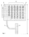
- the top view of the measuring adapter 1 shown in FIG. 1 shows the housing wall 2, which the accesses 3 to the trained as sockets Measuring contacts 4 has.
- a measuring adapter is included twenty-nine measuring contacts, each marked with numbers 4 played.
- the connector on the input side also has 5 and the output connector 6 also each twenty nine contacts.
- Input and output connectors 5, 6 are complementary to each other, the input side as a male connector in the form of a male connector, the output side as a female connector in the form of a socket connector.
- the input connector 5 is permanently installed in the housing, during the Output connector 6 is attached to a cable 7.
- One contact each Male connector 5, the female connector 6 and the measuring contacts 4 are together conductively connected.
- the plug connection of the device to be tested Cable (not shown) separated, the female connector of the cable with the input side 5 of the measuring adapter 1 and the male connector of the cable connected to the output side 6 of the measuring adapter 1.
- the test probe (not shown) of the measuring device inserted and via the internal connection within the measuring adapter 1 the connection to a wire of the cable to be examined is established.
- FIG. 2 shows the circuit board for interconnecting the individual contacts, wherein the top 12 in Figure 2a, the bottom 13 in Figure 2b Circuit board is shown.
- the contacts are 14 of the measuring contacts 4 and the contacts 15 of the input connector 5 not directly connected to each other, but to one Set of three connectors 16 and 16a connected.
- the cable 7 from Figure 1 the one end to 16 and 16a has complementarily designed connectors, while the other Is led outwards and the output connector 6th wearing.
- the set of connectors is 16 or 16a correspondingly dividing the measuring contacts 4 into three groups performed. These groups can be activated individually in which the relevant connector 16, 16a with its complementary Connector is connected.
Landscapes
- Physics & Mathematics (AREA)
- General Physics & Mathematics (AREA)
- Testing Of Short-Circuits, Discontinuities, Leakage, Or Incorrect Line Connections (AREA)
- Coupling Device And Connection With Printed Circuit (AREA)
- Printing Elements For Providing Electric Connections Between Printed Circuits (AREA)
- Testing Electric Properties And Detecting Electric Faults (AREA)
Abstract
Description
- der eingangs- und der ausgangsseitige Steckverbinder
- jeweils komplementär zueinander ausgebildet sind
- und jeweils die gleiche Anzahl an Kontakten aufweisen,
- in gleicher Anzahl Meßkontakte vorhanden sind
- und zwischen je einem Kontakt des eingangsseitigen Steckverbinders, je einem Meßkontakt und je einem Kontakt des ausgangsseitigen
- Schalter
- Brücken
- Steckverbindungen
- Steckverbinder anderer Bauart
- und/oder Steckverbinder mit einer abweichenden Anzahl von Kontakten
- Figur 1:
- Aufsicht auf den Meßadapter
- Figur 2a:
- Verlauf der Leiterbahnen auf der Oberseite der Platine
- Figur 2b:
- Verlauf der Leiterbahnen auf der Unterseite der Platine
Claims (8)
- Vorrichtung zum Prüfen elektrischer Leitungen, die mittels eines Maleund eines Female-Steckers miteinander verbindbar oder mit den genannten Steckern ausrüstbar sind, wobei die Vorrichtung (1) an dessen Eingangs- und Ausgangsseite jeweils mit mindestens einem elektrische Kontakte aufweisenden Steckverbinder (5, 6) ausgestattet ist, dadurch gekennzeichnet, daßder eingangs- und der ausgangsseitige Steckverbinder (5, 6)jeweils komplementär zueinander ausgebildet sindund jeweils die gleiche Anzahl an Kontakten (15) aufweisen,in gleicher Anzahl Meßkontakte (4) vorhanden sind,und zwischen je einem Kontakt (15) des eingangsseitigen Steckverbinders (5), je einem Meßkontakt (14) und je einem Kontakt des ausgangsseitigen Steckverbinders (6) jeweils eine elektrisch leitende Verbindung besteht.
- Vorrichtung zum Prüfen elektrischer Leitungen nach Anspruch 1, dadurch gekennzeichnet, daßaufweisen.die genannten Verbindungen Elemente zum Öffnen und Schließen eines Leiterkreises, wie beispielsweiseSchalterBrückenSteckverbindungen (16, 16a)
- Vorrichtung zum Prüfen elektrischer Leitungen nach Anspruch 1, dadurch gekennzeichnet, daßanschließbar ist.für den eingansseitigen (5) und/oder ausgangsseitigen Steckverbinder (6) jeweils ein Adapter vorgesehen ist, mittels dessen der genannte Steckverbinder jeweils anSteckverbinder anderer Bauartund/oder Steckverbinder mit einer abweichenden Anzahl von Kontakten
- Vorrichtung zum Prüfen elektrischer Leitungen nach Anspruch 1, dadurch gekennzeichnet, daßeingangsseitig und/oder ausgangsseitig mindestens 2 parallel zueinander geschaltete Steckverbinder unterschiedlicher Bauart vorgesehen sind.
- Vorrichtung zum Prüfen elektrischer Leitungen nach Anspruch 1, dadurch gekennzeichnet, daßdie Meßkontakte (14) jeweils als Buchsen ausgebildet sind,die vorzugsweise in einem Raster angeordnet sind.
- Vorrichtung zum Prüfen elektrischer Leitungen nach Anspruch 1, dadurch gekennzeichnet, daßMeßkontakte (14) nach bestimmten Kriterien zu Gruppen zusammengefaßt sind,und den einzelnen Gruppen eingangs- und/oder ausgangsseitig vorzugsweise jeweils ein eigener Steckverbinder zugeordnet ist.
- Vorrichtung zum Prüfen elektrischer Leitungen nach Anspruch 1, dadurch gekennzeichnet, daßauf dem Gehäuse (2) der Vorrichtung Markierungen, vorzugsweise farbliche Markierungen, für die genannten Meßkontakte (4) vorgesehen sind,wobei die genannten Gruppen vorzugsweise gleiche bzw. farblich gleiche Markierungen aufweisen.
- Verwendung der Vorrichtung nach einem der vorangehenden Ansprüche, dadurch gekennzeichnet, daßdie gleiche Vorrichtung (1) sowohl zur Prüfung von Signalleitungen als auch zur Prüfung von Leitungen, die zur Leistungsübertragung vorgesehen sind, eingesetzt wird.
Applications Claiming Priority (2)
| Application Number | Priority Date | Filing Date | Title |
|---|---|---|---|
| DE10149502 | 2001-10-08 | ||
| DE10149502A DE10149502A1 (de) | 2001-10-08 | 2001-10-08 | Vorrichtung zum Prüfen elektrischer Leitungen |
Publications (3)
| Publication Number | Publication Date |
|---|---|
| EP1304579A2 true EP1304579A2 (de) | 2003-04-23 |
| EP1304579A3 EP1304579A3 (de) | 2003-05-02 |
| EP1304579B1 EP1304579B1 (de) | 2009-01-21 |
Family
ID=7701742
Family Applications (1)
| Application Number | Title | Priority Date | Filing Date |
|---|---|---|---|
| EP02017099A Expired - Lifetime EP1304579B1 (de) | 2001-10-08 | 2002-07-30 | Vorrichtung zum Prüfen elektrischer Leitungen |
Country Status (4)
| Country | Link |
|---|---|
| EP (1) | EP1304579B1 (de) |
| AT (1) | ATE421700T1 (de) |
| DE (2) | DE10149502A1 (de) |
| ES (1) | ES2321813T3 (de) |
Cited By (1)
| Publication number | Priority date | Publication date | Assignee | Title |
|---|---|---|---|---|
| CN119165408A (zh) * | 2024-11-20 | 2024-12-20 | 南京全信传输科技股份有限公司 | 湿插拔连接器动压力冲击复合动态测试系统与测试方法 |
Families Citing this family (1)
| Publication number | Priority date | Publication date | Assignee | Title |
|---|---|---|---|---|
| CN112305371B (zh) * | 2020-09-17 | 2024-04-12 | 航天科工空间工程发展有限公司 | 一种适用于航天器电缆网络测试设备、系统和方法 |
Family Cites Families (7)
| Publication number | Priority date | Publication date | Assignee | Title |
|---|---|---|---|---|
| US3818329A (en) * | 1972-08-01 | 1974-06-18 | Western Electric Co | Cable testing circuit employing a pair of diodes to detect specific conductor pair conditions |
| GB2022853B (en) * | 1978-04-12 | 1982-07-14 | Toulouse P D | Identifying conductors in multi-conductor cables |
| FR2649491B1 (fr) * | 1989-07-04 | 1991-10-11 | Electricite De France | Dispositif de verification de cables electriques |
| GB2254439B (en) * | 1990-10-10 | 1995-03-15 | Allan Dickinson | Electrical apparatus |
| US5285163A (en) * | 1992-05-07 | 1994-02-08 | Liotta William A | Electrical cable continuity and voltage tester |
| US5686840A (en) * | 1996-05-08 | 1997-11-11 | Automotive Controls Corporation | Method and apparatus for throttle position sensor testing |
| US6054849A (en) * | 1997-10-17 | 2000-04-25 | Collier; Stephen D. | Electrical testing device |
-
2001
- 2001-10-08 DE DE10149502A patent/DE10149502A1/de not_active Withdrawn
-
2002
- 2002-07-30 ES ES02017099T patent/ES2321813T3/es not_active Expired - Lifetime
- 2002-07-30 AT AT02017099T patent/ATE421700T1/de not_active IP Right Cessation
- 2002-07-30 DE DE50213232T patent/DE50213232D1/de not_active Expired - Lifetime
- 2002-07-30 EP EP02017099A patent/EP1304579B1/de not_active Expired - Lifetime
Cited By (1)
| Publication number | Priority date | Publication date | Assignee | Title |
|---|---|---|---|---|
| CN119165408A (zh) * | 2024-11-20 | 2024-12-20 | 南京全信传输科技股份有限公司 | 湿插拔连接器动压力冲击复合动态测试系统与测试方法 |
Also Published As
| Publication number | Publication date |
|---|---|
| DE50213232D1 (de) | 2009-03-12 |
| EP1304579A3 (de) | 2003-05-02 |
| ATE421700T1 (de) | 2009-02-15 |
| ES2321813T3 (es) | 2009-06-12 |
| EP1304579B1 (de) | 2009-01-21 |
| DE10149502A1 (de) | 2003-04-10 |
Similar Documents
| Publication | Publication Date | Title |
|---|---|---|
| EP0224222B1 (de) | Kabelverbinder | |
| DE4402837C2 (de) | Elektrisches Installationssystem, gebildet durch Flachkabel und Anschlußvorrichtung | |
| DE69603542T2 (de) | Verbindermodule | |
| EP2054978B1 (de) | Anschlusssystem | |
| DE2800006A1 (de) | Universell programmierbarer kurzschliesstecker fuer eine steckfassung einer integrierten schaltung | |
| DE2906030A1 (de) | Anschlussbaustein, insbesondere fuer die verbindung zwischen fernsprech-amtsleitungen und teilnehmerleitungen | |
| DE112011102510T5 (de) | Anschlussleiste | |
| DE102018111733A1 (de) | Leiterkartensteckverbindung | |
| EP3476010B1 (de) | Elektrisches leiteranschlusselement | |
| DE2045474C3 (de) | Kabelanschlußvorrichtung mit Steckkontakten | |
| DE102022112463B4 (de) | Vorrichtung und Anordnung zum Überprüfen der Funktionsfähigkeit einer Ladestation | |
| WO2016107713A1 (de) | Überspannungsschutzanordnung für die informations- und telekommunikationstechnik | |
| DE69931591T2 (de) | Leiterplatte für Modularstecker | |
| DE69710548T2 (de) | Verbinderanordnung für die Statorwicklungen eines elektrischen Motors | |
| EP1360746A1 (de) | Steckvorrichtung mit integrierter diagnose-/auswerteschaltung, anzeige und schaltbaren abschlusswiderständen | |
| EP3607614B1 (de) | Verfahren zum realisieren einer verdrahtung an einer matrix aus leiteranschlussvorrichtungen | |
| DE102016110951B4 (de) | Sicherheitsprüfspitze | |
| EP1304579B1 (de) | Vorrichtung zum Prüfen elektrischer Leitungen | |
| DE10239421B4 (de) | Stecker | |
| DE202011003115U1 (de) | Prüfanschlussvorrichtung für eine Datenbuchse | |
| DE102017203205A1 (de) | Kabelbrückenmodul zur flexiblen verknüpfung von verbindungsklemmen | |
| DE3024643A1 (de) | Flaches elektrisches mehrleiter-verbindungssystem | |
| WO2020078629A1 (de) | Steuerungssystem zur steuerung einer kraftwerksanlage | |
| DE4103634A1 (de) | Positionsmesseinrichtung | |
| DE3423035C2 (de) |
Legal Events
| Date | Code | Title | Description |
|---|---|---|---|
| PUAI | Public reference made under article 153(3) epc to a published international application that has entered the european phase |
Free format text: ORIGINAL CODE: 0009012 |
|
| PUAL | Search report despatched |
Free format text: ORIGINAL CODE: 0009013 |
|
| AK | Designated contracting states |
Designated state(s): AT BE BG CH CY CZ DE DK EE ES FI FR GB GR IE IT LI LU MC NL PT SE SK TR |
|
| AX | Request for extension of the european patent |
Extension state: AL LT LV MK RO SI |
|
| AK | Designated contracting states |
Designated state(s): AT BE BG CH CY CZ DE DK EE ES FI FR GB GR IE IT LI LU MC NL PT SE SK TR |
|
| AX | Request for extension of the european patent |
Extension state: AL LT LV MK RO SI |
|
| 17P | Request for examination filed |
Effective date: 20030425 |
|
| 17Q | First examination report despatched |
Effective date: 20030627 |
|
| AKX | Designation fees paid |
Designated state(s): AT BE BG CH CY CZ DE DK EE ES FI FR GB GR IE IT LI LU MC NL PT SE SK TR |
|
| APBN | Date of receipt of notice of appeal recorded |
Free format text: ORIGINAL CODE: EPIDOSNNOA2E |
|
| APBR | Date of receipt of statement of grounds of appeal recorded |
Free format text: ORIGINAL CODE: EPIDOSNNOA3E |
|
| APAA | Appeal reference recorded |
Free format text: ORIGINAL CODE: EPIDOS REFN |
|
| APBT | Appeal procedure closed |
Free format text: ORIGINAL CODE: EPIDOSNNOA9E |
|
| APAF | Appeal reference modified |
Free format text: ORIGINAL CODE: EPIDOSCREFNE |
|
| APAX | Date of receipt of notice of appeal deleted |
Free format text: ORIGINAL CODE: EPIDOSDNOA2E |
|
| APAZ | Date of receipt of statement of grounds of appeal deleted |
Free format text: ORIGINAL CODE: EPIDOSDNOA3E |
|
| APBN | Date of receipt of notice of appeal recorded |
Free format text: ORIGINAL CODE: EPIDOSNNOA2E |
|
| APBR | Date of receipt of statement of grounds of appeal recorded |
Free format text: ORIGINAL CODE: EPIDOSNNOA3E |
|
| APAF | Appeal reference modified |
Free format text: ORIGINAL CODE: EPIDOSCREFNE |
|
| APBT | Appeal procedure closed |
Free format text: ORIGINAL CODE: EPIDOSNNOA9E |
|
| APBR | Date of receipt of statement of grounds of appeal recorded |
Free format text: ORIGINAL CODE: EPIDOSNNOA3E |
|
| APAF | Appeal reference modified |
Free format text: ORIGINAL CODE: EPIDOSCREFNE |
|
| APBT | Appeal procedure closed |
Free format text: ORIGINAL CODE: EPIDOSNNOA9E |
|
| GRAP | Despatch of communication of intention to grant a patent |
Free format text: ORIGINAL CODE: EPIDOSNIGR1 |
|
| GRAS | Grant fee paid |
Free format text: ORIGINAL CODE: EPIDOSNIGR3 |
|
| GRAA | (expected) grant |
Free format text: ORIGINAL CODE: 0009210 |
|
| AK | Designated contracting states |
Kind code of ref document: B1 Designated state(s): AT BE BG CH CY CZ DE DK EE ES FI FR GB GR IE IT LI LU MC NL PT SE SK TR |
|
| REG | Reference to a national code |
Ref country code: GB Ref legal event code: FG4D Free format text: NOT ENGLISH |
|
| REG | Reference to a national code |
Ref country code: CH Ref legal event code: EP |
|
| GRAC | Information related to communication of intention to grant a patent modified |
Free format text: ORIGINAL CODE: EPIDOSCIGR1 |
|
| REG | Reference to a national code |
Ref country code: IE Ref legal event code: FG4D Free format text: LANGUAGE OF EP DOCUMENT: GERMAN |
|
| REF | Corresponds to: |
Ref document number: 50213232 Country of ref document: DE Date of ref document: 20090312 Kind code of ref document: P |
|
| R17C | First examination report despatched (corrected) |
Effective date: 20030627 |
|
| REG | Reference to a national code |
Ref country code: SE Ref legal event code: TRGR |
|
| PG25 | Lapsed in a contracting state [announced via postgrant information from national office to epo] |
Ref country code: NL Free format text: LAPSE BECAUSE OF FAILURE TO SUBMIT A TRANSLATION OF THE DESCRIPTION OR TO PAY THE FEE WITHIN THE PRESCRIBED TIME-LIMIT Effective date: 20090121 |
|
| REG | Reference to a national code |
Ref country code: ES Ref legal event code: FG2A Ref document number: 2321813 Country of ref document: ES Kind code of ref document: T3 |
|
| NLV1 | Nl: lapsed or annulled due to failure to fulfill the requirements of art. 29p and 29m of the patents act | ||
| PG25 | Lapsed in a contracting state [announced via postgrant information from national office to epo] |
Ref country code: FI Free format text: LAPSE BECAUSE OF FAILURE TO SUBMIT A TRANSLATION OF THE DESCRIPTION OR TO PAY THE FEE WITHIN THE PRESCRIBED TIME-LIMIT Effective date: 20090121 |
|
| REG | Reference to a national code |
Ref country code: IE Ref legal event code: FD4D |
|
| PG25 | Lapsed in a contracting state [announced via postgrant information from national office to epo] |
Ref country code: PT Free format text: LAPSE BECAUSE OF FAILURE TO SUBMIT A TRANSLATION OF THE DESCRIPTION OR TO PAY THE FEE WITHIN THE PRESCRIBED TIME-LIMIT Effective date: 20090622 |
|
| PG25 | Lapsed in a contracting state [announced via postgrant information from national office to epo] |
Ref country code: CZ Free format text: LAPSE BECAUSE OF FAILURE TO SUBMIT A TRANSLATION OF THE DESCRIPTION OR TO PAY THE FEE WITHIN THE PRESCRIBED TIME-LIMIT Effective date: 20090121 Ref country code: EE Free format text: LAPSE BECAUSE OF FAILURE TO SUBMIT A TRANSLATION OF THE DESCRIPTION OR TO PAY THE FEE WITHIN THE PRESCRIBED TIME-LIMIT Effective date: 20090121 Ref country code: DK Free format text: LAPSE BECAUSE OF FAILURE TO SUBMIT A TRANSLATION OF THE DESCRIPTION OR TO PAY THE FEE WITHIN THE PRESCRIBED TIME-LIMIT Effective date: 20090121 Ref country code: IE Free format text: LAPSE BECAUSE OF FAILURE TO SUBMIT A TRANSLATION OF THE DESCRIPTION OR TO PAY THE FEE WITHIN THE PRESCRIBED TIME-LIMIT Effective date: 20090121 |
|
| PLBE | No opposition filed within time limit |
Free format text: ORIGINAL CODE: 0009261 |
|
| STAA | Information on the status of an ep patent application or granted ep patent |
Free format text: STATUS: NO OPPOSITION FILED WITHIN TIME LIMIT |
|
| PG25 | Lapsed in a contracting state [announced via postgrant information from national office to epo] |
Ref country code: SK Free format text: LAPSE BECAUSE OF FAILURE TO SUBMIT A TRANSLATION OF THE DESCRIPTION OR TO PAY THE FEE WITHIN THE PRESCRIBED TIME-LIMIT Effective date: 20090121 |
|
| 26N | No opposition filed |
Effective date: 20091022 |
|
| PG25 | Lapsed in a contracting state [announced via postgrant information from national office to epo] |
Ref country code: BG Free format text: LAPSE BECAUSE OF FAILURE TO SUBMIT A TRANSLATION OF THE DESCRIPTION OR TO PAY THE FEE WITHIN THE PRESCRIBED TIME-LIMIT Effective date: 20090421 |
|
| BERE | Be: lapsed |
Owner name: FRIES, PETER Effective date: 20090731 |
|
| PG25 | Lapsed in a contracting state [announced via postgrant information from national office to epo] |
Ref country code: MC Free format text: LAPSE BECAUSE OF NON-PAYMENT OF DUE FEES Effective date: 20090731 |
|
| REG | Reference to a national code |
Ref country code: CH Ref legal event code: PL |
|
| PG25 | Lapsed in a contracting state [announced via postgrant information from national office to epo] |
Ref country code: CH Free format text: LAPSE BECAUSE OF NON-PAYMENT OF DUE FEES Effective date: 20090731 Ref country code: LI Free format text: LAPSE BECAUSE OF NON-PAYMENT OF DUE FEES Effective date: 20090731 |
|
| PG25 | Lapsed in a contracting state [announced via postgrant information from national office to epo] |
Ref country code: BE Free format text: LAPSE BECAUSE OF NON-PAYMENT OF DUE FEES Effective date: 20090731 |
|
| PG25 | Lapsed in a contracting state [announced via postgrant information from national office to epo] |
Ref country code: GR Free format text: LAPSE BECAUSE OF FAILURE TO SUBMIT A TRANSLATION OF THE DESCRIPTION OR TO PAY THE FEE WITHIN THE PRESCRIBED TIME-LIMIT Effective date: 20090422 |
|
| PGFP | Annual fee paid to national office [announced via postgrant information from national office to epo] |
Ref country code: ES Payment date: 20100726 Year of fee payment: 9 |
|
| PG25 | Lapsed in a contracting state [announced via postgrant information from national office to epo] |
Ref country code: AT Free format text: LAPSE BECAUSE OF NON-PAYMENT OF DUE FEES Effective date: 20090730 |
|
| PGFP | Annual fee paid to national office [announced via postgrant information from national office to epo] |
Ref country code: SE Payment date: 20100723 Year of fee payment: 9 |
|
| PGFP | Annual fee paid to national office [announced via postgrant information from national office to epo] |
Ref country code: GB Payment date: 20100726 Year of fee payment: 9 |
|
| PG25 | Lapsed in a contracting state [announced via postgrant information from national office to epo] |
Ref country code: LU Free format text: LAPSE BECAUSE OF NON-PAYMENT OF DUE FEES Effective date: 20090730 |
|
| PG25 | Lapsed in a contracting state [announced via postgrant information from national office to epo] |
Ref country code: TR Free format text: LAPSE BECAUSE OF FAILURE TO SUBMIT A TRANSLATION OF THE DESCRIPTION OR TO PAY THE FEE WITHIN THE PRESCRIBED TIME-LIMIT Effective date: 20090121 |
|
| PG25 | Lapsed in a contracting state [announced via postgrant information from national office to epo] |
Ref country code: CY Free format text: LAPSE BECAUSE OF FAILURE TO SUBMIT A TRANSLATION OF THE DESCRIPTION OR TO PAY THE FEE WITHIN THE PRESCRIBED TIME-LIMIT Effective date: 20090121 |
|
| PGFP | Annual fee paid to national office [announced via postgrant information from national office to epo] |
Ref country code: IT Payment date: 20110726 Year of fee payment: 10 |
|
| REG | Reference to a national code |
Ref country code: SE Ref legal event code: EUG |
|
| GBPC | Gb: european patent ceased through non-payment of renewal fee |
Effective date: 20110730 |
|
| PG25 | Lapsed in a contracting state [announced via postgrant information from national office to epo] |
Ref country code: GB Free format text: LAPSE BECAUSE OF NON-PAYMENT OF DUE FEES Effective date: 20110730 |
|
| PGFP | Annual fee paid to national office [announced via postgrant information from national office to epo] |
Ref country code: FR Payment date: 20120803 Year of fee payment: 11 |
|
| PG25 | Lapsed in a contracting state [announced via postgrant information from national office to epo] |
Ref country code: SE Free format text: LAPSE BECAUSE OF NON-PAYMENT OF DUE FEES Effective date: 20110731 |
|
| PG25 | Lapsed in a contracting state [announced via postgrant information from national office to epo] |
Ref country code: IT Free format text: LAPSE BECAUSE OF NON-PAYMENT OF DUE FEES Effective date: 20120730 |
|
| REG | Reference to a national code |
Ref country code: ES Ref legal event code: FD2A Effective date: 20130605 |
|
| PG25 | Lapsed in a contracting state [announced via postgrant information from national office to epo] |
Ref country code: ES Free format text: LAPSE BECAUSE OF NON-PAYMENT OF DUE FEES Effective date: 20110731 |
|
| REG | Reference to a national code |
Ref country code: FR Ref legal event code: ST Effective date: 20140331 |
|
| PG25 | Lapsed in a contracting state [announced via postgrant information from national office to epo] |
Ref country code: FR Free format text: LAPSE BECAUSE OF NON-PAYMENT OF DUE FEES Effective date: 20130731 |
|
| PGFP | Annual fee paid to national office [announced via postgrant information from national office to epo] |
Ref country code: DE Payment date: 20160705 Year of fee payment: 15 |
|
| REG | Reference to a national code |
Ref country code: DE Ref legal event code: R119 Ref document number: 50213232 Country of ref document: DE |
|
| PG25 | Lapsed in a contracting state [announced via postgrant information from national office to epo] |
Ref country code: DE Free format text: LAPSE BECAUSE OF NON-PAYMENT OF DUE FEES Effective date: 20180201 |