EP1304487A2 - Series hydraulic circuit for controlling operation of multiple cutting decks of a tractor - Google Patents
Series hydraulic circuit for controlling operation of multiple cutting decks of a tractor Download PDFInfo
- Publication number
- EP1304487A2 EP1304487A2 EP02023185A EP02023185A EP1304487A2 EP 1304487 A2 EP1304487 A2 EP 1304487A2 EP 02023185 A EP02023185 A EP 02023185A EP 02023185 A EP02023185 A EP 02023185A EP 1304487 A2 EP1304487 A2 EP 1304487A2
- Authority
- EP
- European Patent Office
- Prior art keywords
- motor
- flow
- switching means
- fluid
- motors
- Prior art date
- Legal status (The legal status is an assumption and is not a legal conclusion. Google has not performed a legal analysis and makes no representation as to the accuracy of the status listed.)
- Granted
Links
- 239000012530 fluid Substances 0.000 claims description 47
- 230000033001 locomotion Effects 0.000 claims description 5
- 208000036829 Device dislocation Diseases 0.000 claims 1
- 239000007788 liquid Substances 0.000 description 3
- 230000008859 change Effects 0.000 description 2
- 230000003247 decreasing effect Effects 0.000 description 2
- 230000004913 activation Effects 0.000 description 1
- 230000009286 beneficial effect Effects 0.000 description 1
- 238000010586 diagram Methods 0.000 description 1
- 230000026058 directional locomotion Effects 0.000 description 1
- 238000002955 isolation Methods 0.000 description 1
- 238000000034 method Methods 0.000 description 1
- 238000012986 modification Methods 0.000 description 1
- 230000004048 modification Effects 0.000 description 1
- 230000003071 parasitic effect Effects 0.000 description 1
- 230000008569 process Effects 0.000 description 1
- 230000009467 reduction Effects 0.000 description 1
- 238000011144 upstream manufacturing Methods 0.000 description 1
Images

Classifications
-
- F—MECHANICAL ENGINEERING; LIGHTING; HEATING; WEAPONS; BLASTING
- F15—FLUID-PRESSURE ACTUATORS; HYDRAULICS OR PNEUMATICS IN GENERAL
- F15B—SYSTEMS ACTING BY MEANS OF FLUIDS IN GENERAL; FLUID-PRESSURE ACTUATORS, e.g. SERVOMOTORS; DETAILS OF FLUID-PRESSURE SYSTEMS, NOT OTHERWISE PROVIDED FOR
- F15B11/00—Servomotor systems without provision for follow-up action; Circuits therefor
- F15B11/16—Servomotor systems without provision for follow-up action; Circuits therefor with two or more servomotors
- F15B11/161—Servomotor systems without provision for follow-up action; Circuits therefor with two or more servomotors with sensing of servomotor demand or load
- F15B11/162—Servomotor systems without provision for follow-up action; Circuits therefor with two or more servomotors with sensing of servomotor demand or load for giving priority to particular servomotors or users
-
- F—MECHANICAL ENGINEERING; LIGHTING; HEATING; WEAPONS; BLASTING
- F15—FLUID-PRESSURE ACTUATORS; HYDRAULICS OR PNEUMATICS IN GENERAL
- F15B—SYSTEMS ACTING BY MEANS OF FLUIDS IN GENERAL; FLUID-PRESSURE ACTUATORS, e.g. SERVOMOTORS; DETAILS OF FLUID-PRESSURE SYSTEMS, NOT OTHERWISE PROVIDED FOR
- F15B2211/00—Circuits for servomotor systems
- F15B2211/20—Fluid pressure source, e.g. accumulator or variable axial piston pump
- F15B2211/205—Systems with pumps
- F15B2211/20507—Type of prime mover
- F15B2211/20515—Electric motor
-
- F—MECHANICAL ENGINEERING; LIGHTING; HEATING; WEAPONS; BLASTING
- F15—FLUID-PRESSURE ACTUATORS; HYDRAULICS OR PNEUMATICS IN GENERAL
- F15B—SYSTEMS ACTING BY MEANS OF FLUIDS IN GENERAL; FLUID-PRESSURE ACTUATORS, e.g. SERVOMOTORS; DETAILS OF FLUID-PRESSURE SYSTEMS, NOT OTHERWISE PROVIDED FOR
- F15B2211/00—Circuits for servomotor systems
- F15B2211/20—Fluid pressure source, e.g. accumulator or variable axial piston pump
- F15B2211/21—Systems with pressure sources other than pumps, e.g. with a pyrotechnical charge
- F15B2211/214—Systems with pressure sources other than pumps, e.g. with a pyrotechnical charge the pressure sources being hydrotransformers
-
- F—MECHANICAL ENGINEERING; LIGHTING; HEATING; WEAPONS; BLASTING
- F15—FLUID-PRESSURE ACTUATORS; HYDRAULICS OR PNEUMATICS IN GENERAL
- F15B—SYSTEMS ACTING BY MEANS OF FLUIDS IN GENERAL; FLUID-PRESSURE ACTUATORS, e.g. SERVOMOTORS; DETAILS OF FLUID-PRESSURE SYSTEMS, NOT OTHERWISE PROVIDED FOR
- F15B2211/00—Circuits for servomotor systems
- F15B2211/30—Directional control
- F15B2211/31—Directional control characterised by the positions of the valve element
- F15B2211/3105—Neutral or centre positions
- F15B2211/3116—Neutral or centre positions the pump port being open in the centre position, e.g. so-called open centre
-
- F—MECHANICAL ENGINEERING; LIGHTING; HEATING; WEAPONS; BLASTING
- F15—FLUID-PRESSURE ACTUATORS; HYDRAULICS OR PNEUMATICS IN GENERAL
- F15B—SYSTEMS ACTING BY MEANS OF FLUIDS IN GENERAL; FLUID-PRESSURE ACTUATORS, e.g. SERVOMOTORS; DETAILS OF FLUID-PRESSURE SYSTEMS, NOT OTHERWISE PROVIDED FOR
- F15B2211/00—Circuits for servomotor systems
- F15B2211/30—Directional control
- F15B2211/32—Directional control characterised by the type of actuation
- F15B2211/329—Directional control characterised by the type of actuation actuated by fluid pressure
-
- F—MECHANICAL ENGINEERING; LIGHTING; HEATING; WEAPONS; BLASTING
- F15—FLUID-PRESSURE ACTUATORS; HYDRAULICS OR PNEUMATICS IN GENERAL
- F15B—SYSTEMS ACTING BY MEANS OF FLUIDS IN GENERAL; FLUID-PRESSURE ACTUATORS, e.g. SERVOMOTORS; DETAILS OF FLUID-PRESSURE SYSTEMS, NOT OTHERWISE PROVIDED FOR
- F15B2211/00—Circuits for servomotor systems
- F15B2211/50—Pressure control
- F15B2211/505—Pressure control characterised by the type of pressure control means
- F15B2211/50509—Pressure control characterised by the type of pressure control means the pressure control means controlling a pressure upstream of the pressure control means
- F15B2211/50518—Pressure control characterised by the type of pressure control means the pressure control means controlling a pressure upstream of the pressure control means using pressure relief valves
-
- F—MECHANICAL ENGINEERING; LIGHTING; HEATING; WEAPONS; BLASTING
- F15—FLUID-PRESSURE ACTUATORS; HYDRAULICS OR PNEUMATICS IN GENERAL
- F15B—SYSTEMS ACTING BY MEANS OF FLUIDS IN GENERAL; FLUID-PRESSURE ACTUATORS, e.g. SERVOMOTORS; DETAILS OF FLUID-PRESSURE SYSTEMS, NOT OTHERWISE PROVIDED FOR
- F15B2211/00—Circuits for servomotor systems
- F15B2211/50—Pressure control
- F15B2211/515—Pressure control characterised by the connections of the pressure control means in the circuit
- F15B2211/5153—Pressure control characterised by the connections of the pressure control means in the circuit being connected to an output member and a directional control valve
- F15B2211/5154—Pressure control characterised by the connections of the pressure control means in the circuit being connected to an output member and a directional control valve being connected to multiple ports of an output member
-
- F—MECHANICAL ENGINEERING; LIGHTING; HEATING; WEAPONS; BLASTING
- F15—FLUID-PRESSURE ACTUATORS; HYDRAULICS OR PNEUMATICS IN GENERAL
- F15B—SYSTEMS ACTING BY MEANS OF FLUIDS IN GENERAL; FLUID-PRESSURE ACTUATORS, e.g. SERVOMOTORS; DETAILS OF FLUID-PRESSURE SYSTEMS, NOT OTHERWISE PROVIDED FOR
- F15B2211/00—Circuits for servomotor systems
- F15B2211/50—Pressure control
- F15B2211/55—Pressure control for limiting a pressure up to a maximum pressure, e.g. by using a pressure relief valve
-
- F—MECHANICAL ENGINEERING; LIGHTING; HEATING; WEAPONS; BLASTING
- F15—FLUID-PRESSURE ACTUATORS; HYDRAULICS OR PNEUMATICS IN GENERAL
- F15B—SYSTEMS ACTING BY MEANS OF FLUIDS IN GENERAL; FLUID-PRESSURE ACTUATORS, e.g. SERVOMOTORS; DETAILS OF FLUID-PRESSURE SYSTEMS, NOT OTHERWISE PROVIDED FOR
- F15B2211/00—Circuits for servomotor systems
- F15B2211/60—Circuit components or control therefor
- F15B2211/635—Circuits providing pilot pressure to pilot pressure-controlled fluid circuit elements
- F15B2211/6355—Circuits providing pilot pressure to pilot pressure-controlled fluid circuit elements having valve means
-
- F—MECHANICAL ENGINEERING; LIGHTING; HEATING; WEAPONS; BLASTING
- F15—FLUID-PRESSURE ACTUATORS; HYDRAULICS OR PNEUMATICS IN GENERAL
- F15B—SYSTEMS ACTING BY MEANS OF FLUIDS IN GENERAL; FLUID-PRESSURE ACTUATORS, e.g. SERVOMOTORS; DETAILS OF FLUID-PRESSURE SYSTEMS, NOT OTHERWISE PROVIDED FOR
- F15B2211/00—Circuits for servomotor systems
- F15B2211/70—Output members, e.g. hydraulic motors or cylinders or control therefor
- F15B2211/705—Output members, e.g. hydraulic motors or cylinders or control therefor characterised by the type of output members or actuators
- F15B2211/7058—Rotary output members
-
- F—MECHANICAL ENGINEERING; LIGHTING; HEATING; WEAPONS; BLASTING
- F15—FLUID-PRESSURE ACTUATORS; HYDRAULICS OR PNEUMATICS IN GENERAL
- F15B—SYSTEMS ACTING BY MEANS OF FLUIDS IN GENERAL; FLUID-PRESSURE ACTUATORS, e.g. SERVOMOTORS; DETAILS OF FLUID-PRESSURE SYSTEMS, NOT OTHERWISE PROVIDED FOR
- F15B2211/00—Circuits for servomotor systems
- F15B2211/70—Output members, e.g. hydraulic motors or cylinders or control therefor
- F15B2211/71—Multiple output members, e.g. multiple hydraulic motors or cylinders
Definitions
- This invention relates generally to an electro-hydraulic control valve and more specifically, to the use of such a control valve in a series hydraulic circuit to simultaneously and separately control the operation of multiple cutting decks of a mowing tractor.
- a first design has included providing a separate circuit for each of the motors, and thus the devices whose motion they control.
- a second design has included providing a single circuit and connecting each of the motors in series whereby flow to a particular motor can be accomplished through control of an associated valve manifold or collection of valves within the circuit.
- US-A-3,631,930 shows a bulldozer with a hydraulic pump driven by an engine and having four fluid motors with control valves adapted to supply fluid to all four motors in series. Theses control valves are manually activated and therefore inconvenient in handling.
- a hydraulic circuit which allows for the direction of hydraulic flow to a combination of motors and which includes a minimum number of parts to control that flow while preventing its unintended redirection.
- the circuit In directing flow among at least three motors, the circuit allows for the operation of a front or first motor by itself. Additionally, since it is designed to align the motors in series, the circuit permits the operation of the front motor alone, the front and a left or second motor, the front motor and a right or third motor, or alternatively, operation of all three motors and their attached devices simultaneously.
- the circuit provides a switchable connection for directing the exit flow of the front motor through the manifold, bypassing the left and right motor.
- the flow path along which fluid from the front motor is communicated through the manifold is substantially prevented from entering the hydraulic lines servicing either the left or right motors.
- the flow supplying the second or third motor when operating separately, is substantially prevented from entering the hydraulic lines servicing the other of the second and third motors.
- the circuit is enabled to accomplish the efficient flow and individual operation of three motors, or a combination thereof, in a cost effective manner due to unneeded flow controls.
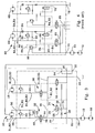
- FIG 1 there is shown a hydraulic circuit 10 for controlling flow of hydraulic liquid to one or a combination of each of three motors 12, 14, 16 whereby each of these motors moves a device (not shown), such as a blade of the lawn and garden tractor, for its intended purpose.
- a device such as a blade of the lawn and garden tractor
- FIG. 1 Each of the front, left and right motors 12, 14, 16, respectively, are designated in the diagram of Figure 1.
- the circuit 10 permits operation of the front motor alone or in combination with the right and/or left motor by controlling the flow and associated pressurization of the flow in each of the hydraulic lines which services their respective motor.
- the circuit 10 permits the flow of hydraulic liquid in each of three patterns R1; R1,R2 and R1,R2,R3.
- R1 represents the flow of fluid which supplies the front motor 12 and which is then circulated through the circuit 10.
- a hydraulic pump 18 is provided as part of the vehicle engine (not shown). Upon activation of a pressurized control switch (not shown), the pump 18 will supply fluid to the front motor 12 and then through an inlet 20 whereby it is then further distributed through the circuit 10 along the path R1, as shown in Figure 1, until it exits through an outlet 22.
- FIG 2 the flow of the hydraulic fluid permitting operation of the front and left motors 12 and 14, respectively, is shown and represented as R1, R2.
- fluid is supplied by the pump 18 through both the front motor 12 and the inlet 20. This flow is R1.
- an operator will lower the left mower deck (not shown) into its operating position via a control lever (not shown), which is located on the tractor operator's panel, to cause the flow R1,R2.
- a first switching means in the form of a two position, three way solenoid operated directional control valve 24, will become energized by an electric current, causing the valve to shift from a first or "closed” position shown in Figure 1 to a second or “open” position shown in Figure 2.
- This change to the "open” position allows flow to be communicated between the ports 28 and 30 of the valve 24.
- hydraulic fluid is passed onward, as a pilot signal, to shift an externally pilot operated two position, four way directional control valve 32 or first fluid transfer means (discussed below).
- the directional control valve 32 prior to the energizing of the solenoid valve 24, is closed, as is shown in Figure 1, and is opened as shown in Figure 2 by pressure from flow which has passed through the solenoid valve 24, as has been previously stated.
- the directional valve 32 has four ports 38, 40, 42 and 44 therein whereby fluid can be passed through the port 38 to the port 44 whereby the ports 40 and 42 are closed to the motor 14.
- a second switching means in the form of a solenoid valve 55 will become energized in a fashion similar to that occurring with the valve 24.
- the flow R1 will bypass the directional valve 32 in its first or “closed” position whereby the fluid flows and is passed through a second fluid transfer means or directional control valve 56 and then through the right motor 16.
- a flow pattern similar to that of R1, R2 may be used to symbolize the supply and directional movement of fluid directed to the right motor 16.
- a drain 54 is provided to receive excess drainage from the right motor 16.
- each of the solenoid valves 24, 55 will be separately shifted whereby this change in position can be seen when looking at Figures 1 and 3. With this shifting, the respective directional control valves 32 and 56 will move to their second or open position so as to permit their ports to be opened and allow the flow of fluid therethrough.
- the left and right motors 14 and 16 will be made operational as hydraulic fluid is then able to be delivered to them.
- actuation of both solenoid valves 24 and 55 associated with the left and right motors 14 and 16, respectively establishes a flow path R1, R2, R3.
- the flow of hydraulic fluid exiting the left motor 14 may do so only in one direction which is directed towards the outlet 22. Consequently, flow is permitted to be directed only in a first entry and exit direction with respect to supplying the right motor 16; therefore, instances in which the flow R1,R2 (supplied to the right motor 16) could to re-enter the supply lines of the left motor 14, with a directional flow which is different than that which has been described, are substantially prevented.
- flow patterns R1,R2 and R1,R2,R3 each include a relief such as the valve 60 therealong, which is provided to release excess fluid in the circuit when a sudden increase in pressure driving the flow thereof is experienced.
- a sudden increase in pressure may occur, as in the case of a rotating mower blade, when an object impacts the blade causing it to suddenly slow or stop so as to affect the work done by its respective motor.
- the fluid pressure along R1, R2 may be higher at the port 48 than that at the port 50 when an object impacts the blade.
- the operator will raise the left mower deck so as to cut the electrical signal to its associated solenoid valve 24.
- the solenoid valve 24 is shifted to its first or closed position creating a flow path from the port 29 to the port 30, as shown in Figure 1, so as to connect it to the tank 36 along a line 34.
- This allows the directional control valve 32 to return to its first or closed position due to a spring force acting on it to connect the ports 38 to 44 and close the ports 40 and 42.
- the left motor 14 still possessing inertia due to the rotation of its blade, the inertia will try to move the trapped fluid from the port 48 to the port 50.
- the momentum of the blade must be dissipated in a set time and is accomplished by the spring loaded check valve 58. Since the pressure is lower on the left side of the motor 14 than on the right side thereof, the valve 58 will allow flow to pass through, from right to left. The flow is then returned to the left motor 14 through the port 48. This path is repeated until the motor 14 is brought to a stop. A similar system can be seen in the right motor circuit.
- FIG 4 there is shown a hydraulic circuit 62 of the prior art whereby each of the front, left and right motors 64, 66 and 68, respectively, are connected in series.
- the routing of flow through the circuit 62 requires a number of valves which are not present in the instant invention.
- fluid transmitted through the inlet 70 by a pump 72 will service a front motor 64 and be communicated along the path R4.
- the hydraulic fluid Upon entry into the path R4, the hydraulic fluid will pass through the ports of a first logic control valve 74 which acts to pass flow to the also open ports of a second logic control valve 76 and towards the outlet 78.
- a loop beginning with the pilot check valve 84 is created to restrict the flow which exits across the motor 66 when the circuit is turned off so as to slow the motor 66 and subsequently the blade thereof.
- the left motor 66 is taken out of, or not serviced by, the flow path R4,R5 by cutting power to its associated solenoid valve 82 so as to shift the pilot signal and redirect the flow R4 to cross the logic valve 74, the entire process closing off the logic valve 80 and the flow R4,R5 used to feed the motor 66.
- momentum of the motor 66 must be dissipated in order to stop motion of the blade.
- the pilot check valve 84 is allowed to close, restricting the flow from the motor 66 and returning it in a closed loop fashion, as discussed in relation to the motor 14, to the motor 66 across the check valve 90 until the motor has been stopped.
- the system experiences undesirable pressure drop(s) as a result of directing the flow R4, R5 through the valves 84 and 86 and causes an associated loss in efficiency across the circuit.
- a hydraulic circuit 10 which connects each of three motors 12, 14 and 16 in series while eliminating restrictive valves within the operating flow path to allow for increased efficiency across the circuit 10.
- This increase in efficiency is permitted by eliminating valves such as the check valve 86.
- This increase is accomplished since the flows R1 and R1,R2 are routed into and out of their associated fluid transfer means, thereby achieving achieving isolation of the left and/or right motor(s) so as to block flow not associated with either of those motors from inadvertently reentering it.
Landscapes
- Engineering & Computer Science (AREA)
- Physics & Mathematics (AREA)
- Fluid Mechanics (AREA)
- Mechanical Engineering (AREA)
- General Engineering & Computer Science (AREA)
- Fluid-Pressure Circuits (AREA)
- Harvester Elements (AREA)
Abstract
Description
- This invention relates generally to an electro-hydraulic control valve and more specifically, to the use of such a control valve in a series hydraulic circuit to simultaneously and separately control the operation of multiple cutting decks of a mowing tractor.
- It is known to provide a hydraulic circuit to conduct the flow of hydraulic fluid so as to allow a motor of a vehicle, such as a mower, to be operated. Typically, these circuits are provided with a series of valves and switches to direct the flow of that liquid, whereby pressure associated with that flow to that motor permits its device, a blade as in the case of a mowing tractor, to move.
- In providing these circuits, at least two designs have been used to accomplish the above. A first design has included providing a separate circuit for each of the motors, and thus the devices whose motion they control. A second design has included providing a single circuit and connecting each of the motors in series whereby flow to a particular motor can be accomplished through control of an associated valve manifold or collection of valves within the circuit.
- US-A-3,631,930 shows a bulldozer with a hydraulic pump driven by an engine and having four fluid motors with control valves adapted to supply fluid to all four motors in series. Theses control valves are manually activated and therefore inconvenient in handling.
- With each of the above designs, disadvantages exist. In the case of providing a separate circuit for each of the separate motors, each circuit would require its own pump and control valve whereby the cost of doing so disfavors providing an economical product to the consumer. In the case of providing a circuit having each of the motors connected in series, efficiency, or the ratio of the work output to the work input across a system, is often decreased. This decreased efficiency results from drops in pressure across the valves which control the direction and function of flow and pressure through the circuit. These valves exist to regulate, as stated above, the pressure across the circuit when it is necessary to control the flow of hydraulic fluid to a first motor while preventing flow to one or more of a series of motors when it is desired to only operate one or a combination thereof. As fluid passes over these valves, the system experiences a drop in fluid pressure causing the system to be less efficient than it could otherwise be. Additionally, cost disadvantages also exist in this design due to the provision of these control valves.
- Thus, it would be beneficial to provide a circuit which could allow for the control of multiple motors in a series circuit while doing so with low parasitic loss, or the pressure drop across the manifold, and a minimal number of valves within the manifold as a result of how fluid is directed to a particular motor.
- Accordingly, there is provided a hydraulic circuit which allows for the direction of hydraulic flow to a combination of motors and which includes a minimum number of parts to control that flow while preventing its unintended redirection.
- In directing flow among at least three motors, the circuit allows for the operation of a front or first motor by itself. Additionally, since it is designed to align the motors in series, the circuit permits the operation of the front motor alone, the front and a left or second motor, the front motor and a right or third motor, or alternatively, operation of all three motors and their attached devices simultaneously.
- To allow fluid to be communicated to at least the front motor without that flow being permitted to enter the flow path of the left and right motors, the circuit provides a switchable connection for directing the exit flow of the front motor through the manifold, bypassing the left and right motor. In other words, the flow path along which fluid from the front motor is communicated through the manifold is substantially prevented from entering the hydraulic lines servicing either the left or right motors. Further, the flow supplying the second or third motor, when operating separately, is substantially prevented from entering the hydraulic lines servicing the other of the second and third motors. Finally, when each of the second and third motors are operating, the supply of fluid from the first motor is delivered, initially, to a second motor whose exit flow is delivered to a third motor whose exit flow is then directed to an outlet.
- Accordingly, the circuit is enabled to accomplish the efficient flow and individual operation of three motors, or a combination thereof, in a cost effective manner due to unneeded flow controls.
- FIG. 1
- is a schematic of the hydraulic circuit according to the instant invention whereby only the front motor is operating.
- FIG. 2
- is a schematic of the circuit showing the operation of both the front and left motors.
- FIG. 3
- is a schematic of the circuit showing the operation of the front, left and right motors.
- FIG. 4
- is a schematic of a series hydraulic circuit of the prior art whereby only the front motor is operating.
- Looking to Figure 1, there is shown a
hydraulic circuit 10 for controlling flow of hydraulic liquid to one or a combination of each of threemotors right motors circuit 10 permits operation of the front motor alone or in combination with the right and/or left motor by controlling the flow and associated pressurization of the flow in each of the hydraulic lines which services their respective motor. - As shown in Figures 1-3, the
circuit 10 permits the flow of hydraulic liquid in each of three patterns R1; R1,R2 and R1,R2,R3. As shown in Figure 1, R1 represents the flow of fluid which supplies thefront motor 12 and which is then circulated through thecircuit 10. As is shown, ahydraulic pump 18 is provided as part of the vehicle engine (not shown). Upon activation of a pressurized control switch (not shown), thepump 18 will supply fluid to thefront motor 12 and then through aninlet 20 whereby it is then further distributed through thecircuit 10 along the path R1, as shown in Figure 1, until it exits through anoutlet 22. - Looking to Figure 2, the flow of the hydraulic fluid permitting operation of the front and
left motors pump 18 through both thefront motor 12 and theinlet 20. This flow is R1. However, when it is intended that theleft motor 14 be made operational, an operator will lower the left mower deck (not shown) into its operating position via a control lever (not shown), which is located on the tractor operator's panel, to cause the flow R1,R2. - Upon the operator lowering the left mower deck into position, a first switching means in the form of a two position, three way solenoid operated
directional control valve 24, will become energized by an electric current, causing the valve to shift from a first or "closed" position shown in Figure 1 to a second or "open" position shown in Figure 2. This change to the "open" position allows flow to be communicated between theports valve 24. After flowing through thevalve 24, hydraulic fluid is passed onward, as a pilot signal, to shift an externally pilot operated two position, four waydirectional control valve 32 or first fluid transfer means (discussed below). - The
directional control valve 32, prior to the energizing of thesolenoid valve 24, is closed, as is shown in Figure 1, and is opened as shown in Figure 2 by pressure from flow which has passed through thesolenoid valve 24, as has been previously stated. As shown in Figure 1, thedirectional valve 32 has fourports port 38 to theport 44 whereby theports motor 14. Referring to Figure 2, it is seen that upon pressurization by fluid traveling along aline 46 as a result of energizing thesolenoid valve 24, thedirectional valve 32 and itsports 38 to 40 and 42 to 44 are opened so as to allow the main flow of fluid R1 supplying thefront motor 12 to flow vertically upward therethrough and along a path R1,R2 through anexit port 48 which supplies and permits fluid to be passed through theleft motor 14. After passing through themotor 14, the fluid re-enters the path R1,R2 through theport 50 where it then continues towards theoutlet 22. Fluid which escapes themotor 14 and which does not flow along the path R1,R2 is routed to adrain port 52 which is combined with the drain flow of thedirectional valve 32 and is then returned to thetank 36. A similar directional flow can be conducted in a corresponding manner when it is desired that theright motor 16 be made operational. - When operability of the front and
right motors solenoid valve 55 will become energized in a fashion similar to that occurring with thevalve 24. The flow R1 will bypass thedirectional valve 32 in its first or "closed" position whereby the fluid flows and is passed through a second fluid transfer means ordirectional control valve 56 and then through theright motor 16. As such, a flow pattern similar to that of R1, R2 may be used to symbolize the supply and directional movement of fluid directed to theright motor 16. Similarly, adrain 54 is provided to receive excess drainage from theright motor 16. - When it is desired that each of the front, left and
right motors solenoid valves directional control valves - Accordingly, the left and
right motors solenoid valves right motors left motor 14 may do so only in one direction which is directed towards theoutlet 22. Consequently, flow is permitted to be directed only in a first entry and exit direction with respect to supplying theright motor 16; therefore, instances in which the flow R1,R2 (supplied to the right motor 16) could to re-enter the supply lines of theleft motor 14, with a directional flow which is different than that which has been described, are substantially prevented. - As also shown in Figures 1-3, flow patterns R1,R2 and R1,R2,R3 each include a relief such as the
valve 60 therealong, which is provided to release excess fluid in the circuit when a sudden increase in pressure driving the flow thereof is experienced. Such an increase in pressure may occur, as in the case of a rotating mower blade, when an object impacts the blade causing it to suddenly slow or stop so as to affect the work done by its respective motor. For example, the fluid pressure along R1, R2 may be higher at theport 48 than that at theport 50 when an object impacts the blade. Because thefront motor 12 is operating upstream of themotor 14 in the series circuit and possesses inertia, or a tendency to move the fluid therein due to the rotation of its blade, obstructions affecting theleft motor 14 will cause the inertia of themotor 12 to yield a sudden increase in pressure in R1, R2. As the flow R1, R2 is directed through the circuit, this pressure will be released through therelief valve 60 if it increases in an amount greater than that of the relief valve setting so as to bypass the obstructedmotor 14 and preventing damage to its components. This component protection system can also be seen in the R1, R2, R3 flow path. Where an obstruction affects theright motor 16, the fluid will resume traveling along the designated pattern R1,R2,R3 towards theoutlet 22, bypassing theright motor 16. - During operation, if it is desired to disengage the
left motor 14, the operator will raise the left mower deck so as to cut the electrical signal to its associatedsolenoid valve 24. In turn, thesolenoid valve 24 is shifted to its first or closed position creating a flow path from theport 29 to theport 30, as shown in Figure 1, so as to connect it to thetank 36 along aline 34. This allows thedirectional control valve 32 to return to its first or closed position due to a spring force acting on it to connect theports 38 to 44 and close theports left motor 14 still possessing inertia due to the rotation of its blade, the inertia will try to move the trapped fluid from theport 48 to theport 50. Ordinarily, the momentum of the blade must be dissipated in a set time and is accomplished by the spring loadedcheck valve 58. Since the pressure is lower on the left side of themotor 14 than on the right side thereof, thevalve 58 will allow flow to pass through, from right to left. The flow is then returned to theleft motor 14 through theport 48. This path is repeated until themotor 14 is brought to a stop. A similar system can be seen in the right motor circuit. - Looking to Figure 4, there is shown a
hydraulic circuit 62 of the prior art whereby each of the front, left andright motors front motor 64 to be operated in combination with either of the left orright motors circuit 62, the routing of flow through thecircuit 62 requires a number of valves which are not present in the instant invention. As can be seen, fluid transmitted through theinlet 70 by apump 72 will service afront motor 64 and be communicated along the path R4. Upon entry into the path R4, the hydraulic fluid will pass through the ports of a firstlogic control valve 74 which acts to pass flow to the also open ports of a secondlogic control valve 76 and towards theoutlet 78. - In the case in which it is desired to operate the front and left
motors logic control valve 80 and then along a path R4,R5 after asolenoid valve 82 has been energized by the operator having switched the control for theleft motor 66 located on the vehicle operator's panel. The shifting of thesolenoid valve 82 allows a pilot signal from R4, in the form of pressure, to shift thelogic valve 74 to its closed position while connecting thepilot line 83 from thelogic valve 80 to thetank 85 allowing it to open a flow path for R4 to themotor 66. Along this path, the flow R4,R5 will encounter apilot check valve 84 used for braking the motor upon shut down as well as acheck valve 86 used to regulate flow only in the downward direction. Thereafter, the flow will continue to exit the system along the path designated R4,R5. With the flow just described being similar in nature for that required to obtain operation of theright motor 68, only the operation of and the flow designated R4,R5 servicing theleft motor 66 has been described. - As can be seen in Figure 4, should operation of the
right motor 68 be desired, it is possible for its associated flow to be diverted backward towards thecheck valve 86. Consequently, due to the routing of the flow R4,R5, thecheck valve 86 is required to prevent the redirection of that flow R4,R5 towards theleft motor 66. In providing thisvalve 86, the flow R4,R5 crosses it and will experience a further drop in pressure as a result of its placement. This drop in pressure, as discussed previously, causes a reduction in the amount of work done by the system so as to also cause a related drop in the efficiency of the circuit overall. - Additionally, with respect to instances in which the blade or other device powered by the
left motor 66 is operating, a loop beginning with thepilot check valve 84 is created to restrict the flow which exits across themotor 66 when the circuit is turned off so as to slow themotor 66 and subsequently the blade thereof. Theleft motor 66 is taken out of, or not serviced by, the flow path R4,R5 by cutting power to its associatedsolenoid valve 82 so as to shift the pilot signal and redirect the flow R4 to cross thelogic valve 74, the entire process closing off thelogic valve 80 and the flow R4,R5 used to feed themotor 66. As described above, momentum of themotor 66 must be dissipated in order to stop motion of the blade. Once pressure is reduced on the inlet side of themotor 66 at the left side thereof, thepilot check valve 84 is allowed to close, restricting the flow from themotor 66 and returning it in a closed loop fashion, as discussed in relation to themotor 14, to themotor 66 across thecheck valve 90 until the motor has been stopped. During operation, the system experiences undesirable pressure drop(s) as a result of directing the flow R4, R5 through thevalves - Thus, in contrast to the
circuit 62 just described and shown in Figure 4, there is provided ahydraulic circuit 10 which connects each of threemotors circuit 10. This increase in efficiency is permitted by eliminating valves such as thecheck valve 86. This increase is accomplished since the flows R1 and R1,R2 are routed into and out of their associated fluid transfer means, thereby achieving achieving isolation of the left and/or right motor(s) so as to block flow not associated with either of those motors from inadvertently reentering it. - Having described the preferred embodiment, it will become apparent that various modifications can be made without departing from the scope of the invention as defined in the accompanying claims.
Claims (4)
- In a vehicle having an engine and including a plurality of motors ((12, 14, 16), each transmitting motion to a respective device, and which are connected to a pump (18) for delivering a flow of hydraulic fluid to at least a first motor (12) in a series of motors (12, 14, 16), a circuit (10) for controlling that flow of the hydraulic fluid to the series of motors (12, 14, 16) so as to permit their simultaneous or individual operation, the circuit (10) comprising:a) an inlet through which fluid supplied to the first motor is passed;b) an outlet through which the fluid may exit so as to be available for return to the system;c) a first and second switching means (24, 55), each having a first and second position, the fluid being restricted from flowing between the inlet and outlet when the switching means (24, 55) are in their first position and unrestricted therebetween when the switching means (24, 55) are in their second position;d) a first fluid transfer means (32, 56), having first and second positions, and which is associated with the first switching means (24) for directing flow to or away from a second motor (14), the first transfer means (32) having ports (38, 40, 42, 44) defining a flow path therethrough, the ports (38, 40, 42, 44) thereof being closed to the second motor (14) while allowing flow to bypass through the first transfer means (32) when the first switching means (24) is in its first position, the ports (38, 40, 42, 44) thereof being open to the second motor (14) when the first switching means (24) is in its second position so as to permit flow to the second motor (14);e) a second fluid transfer means (56), having first and second positions, and which is associated with the second switching means (55) for directing flow to or away from a third motor (16), the second transfer means (56) having ports defining a flow path therethrough, the ports thereof being closed to the third motor (16) while allowing flow to bypass through the second transfer means (56) when the second switching means (55) is in its first position, the ports thereof being open to the third motor (16) when the second switching means (55) is in its second position so as to allow flow to the third motor (16); andf) flow is directed between the inlet and the second motor and then to the outlet when the first switching means(24) is in its second position and the second switching means (55) is its first position, and flow is directed between the inlet and the third motor (16) and then to the outlet when the first switching means (24) is in its first position and the second switching means (55) is in its second position, movement of at least one of the first and second switching means (24, 55) to its first or second position redirects flow to or away from one of the second and third motors (14, 16), respectively, while then directing that flow along a substantially uninterrupted path toward the outlet.
- The invention of claim 1 characterized in that the flows which are passable through the first and second fluid transfer means (32, 56), respectively, and which are routable into and out of those transfer means (32, 56) when the first and/or second switching means (24, 55) is in the second position, respectively, each include only one valve therealong which provides an open flow path to and from its respective motor (14, 16) to reduce loss in pressure across that flow path, thereby reducing loss in its efficiency while maintaining an ability to dissipate momentum of a device moved by the motor (14, 16) when that motor (14, 16) is no longer supplied by fluid passing through its respective transfer means (32, 56) and preventing movement of flow into one of the second and third motors (14, 16) when the other of the second and third motors (14, 16) is operating.
- The invention of claim 1 or 2, characterized in that the the first and second positions of the switching means (24, 55) and the fluid transfer means (32, 56) indicate a "closed" and "open" position, respectively.
- The invention of one or several of the claims 1 to 3, characterized in that the first and second switching means (24, 55) are solenoid operated directional control valves, and the first and second fluid transfer (32, 56) means are pilot operated directional control valves.
Applications Claiming Priority (2)
| Application Number | Priority Date | Filing Date | Title |
|---|---|---|---|
| US09/982,914 US7415919B2 (en) | 2001-10-19 | 2001-10-19 | Series hydraulic circuit for controlling operation of multiple cutting decks of a tractor |
| US982914 | 2001-10-19 |
Publications (3)
| Publication Number | Publication Date |
|---|---|
| EP1304487A2 true EP1304487A2 (en) | 2003-04-23 |
| EP1304487A3 EP1304487A3 (en) | 2006-04-19 |
| EP1304487B1 EP1304487B1 (en) | 2009-01-14 |
Family
ID=25529632
Family Applications (1)
| Application Number | Title | Priority Date | Filing Date |
|---|---|---|---|
| EP02023185A Expired - Lifetime EP1304487B1 (en) | 2001-10-19 | 2002-10-16 | Series hydraulic circuit for controlling operation of multiple cutting decks of a tractor |
Country Status (4)
| Country | Link |
|---|---|
| US (1) | US7415919B2 (en) |
| EP (1) | EP1304487B1 (en) |
| CA (1) | CA2404208A1 (en) |
| DE (1) | DE60230849D1 (en) |
Families Citing this family (1)
| Publication number | Priority date | Publication date | Assignee | Title |
|---|---|---|---|---|
| US7437864B2 (en) * | 2007-02-16 | 2008-10-21 | Deere & Company | Shift mechanism for trim mower cutting units |
Citations (2)
| Publication number | Priority date | Publication date | Assignee | Title |
|---|---|---|---|---|
| US3631930A (en) | 1969-07-07 | 1972-01-04 | Caterpillar Tractor Co | Mounting arrangement for bulldozer blades |
| DE19526909A1 (en) | 1995-07-22 | 1997-01-23 | Rexroth Mannesmann Gmbh | Hydraulic drive, e.g. for rubbish compacting vehicle |
Family Cites Families (11)
| Publication number | Priority date | Publication date | Assignee | Title |
|---|---|---|---|---|
| US3348624A (en) * | 1965-04-28 | 1967-10-24 | Aquatic Controls Corp | Hydraulic propulsion system |
| US3713296A (en) * | 1972-02-15 | 1973-01-30 | D Black | Hydraulic system for individually controlling a plurality of hydraulic motors |
| US3991832A (en) * | 1975-07-14 | 1976-11-16 | Deere & Company | Hydraulically tiltable and anglable dozer blade and mounting therefor |
| US3987622A (en) * | 1976-02-02 | 1976-10-26 | Caterpillar Tractor Co. | Load controlled fluid system having parallel work elements |
| FR2357764A1 (en) * | 1976-07-06 | 1978-02-03 | Poclain Sa | AT LEAST TWO FLUID MOTOR UNITS |
| US4206580A (en) * | 1977-12-01 | 1980-06-10 | Traux Clarence E | Mower device |
| US4276896A (en) * | 1979-11-05 | 1981-07-07 | Deere & Company | Flow control valve assembly with integrated torque and flow divider control |
| JPS59185234A (en) | 1983-04-05 | 1984-10-20 | Kubota Ltd | Front loader control device |
| JPS6092187A (en) | 1983-10-24 | 1985-05-23 | Kawasaki Heavy Ind Ltd | Hydraulic on-off gear for hatch cover |
| JP2556697B2 (en) | 1987-03-30 | 1996-11-20 | 三陽機器株式会社 | Hydraulic device for dumper control of loader |
| DE3901349A1 (en) | 1989-01-18 | 1990-07-19 | Rexroth Mannesmann Gmbh | Valve arrangement for several hydraulic consumers |
-
2001
- 2001-10-19 US US09/982,914 patent/US7415919B2/en not_active Expired - Lifetime
-
2002
- 2002-09-19 CA CA002404208A patent/CA2404208A1/en not_active Abandoned
- 2002-10-16 EP EP02023185A patent/EP1304487B1/en not_active Expired - Lifetime
- 2002-10-16 DE DE60230849T patent/DE60230849D1/en not_active Expired - Lifetime
Patent Citations (2)
| Publication number | Priority date | Publication date | Assignee | Title |
|---|---|---|---|---|
| US3631930A (en) | 1969-07-07 | 1972-01-04 | Caterpillar Tractor Co | Mounting arrangement for bulldozer blades |
| DE19526909A1 (en) | 1995-07-22 | 1997-01-23 | Rexroth Mannesmann Gmbh | Hydraulic drive, e.g. for rubbish compacting vehicle |
Also Published As
| Publication number | Publication date |
|---|---|
| EP1304487A3 (en) | 2006-04-19 |
| EP1304487B1 (en) | 2009-01-14 |
| US7415919B2 (en) | 2008-08-26 |
| CA2404208A1 (en) | 2003-04-19 |
| DE60230849D1 (en) | 2009-03-05 |
| US20030075040A1 (en) | 2003-04-24 |
Similar Documents
| Publication | Publication Date | Title |
|---|---|---|
| US9091281B2 (en) | System for allocating fluid from multiple pumps to a plurality of hydraulic functions on a priority basis | |
| JP3689211B2 (en) | Flow confluence device for heavy equipment | |
| US5148676A (en) | Confluence valve circuit of a hydraulic excavator | |
| US8051651B2 (en) | Hydraulic flow control system | |
| US5081837A (en) | Hydraulic control circuit | |
| JPH07332308A (en) | Hydraulic drive controller | |
| US6453585B1 (en) | Hydraulic drive device of working machine | |
| KR19990009721A (en) | Heavy duty flow distribution device with multiple actuators | |
| KR100797315B1 (en) | Hydraulic control device for complex operation of traveling and front work of excavator | |
| EP3492661B1 (en) | Excavator, and control valve for excavator | |
| US12410588B2 (en) | Hydraulic control system in working machine | |
| US7165397B2 (en) | Anti-stall pilot pressure control system for open center systems | |
| EP1304487B1 (en) | Series hydraulic circuit for controlling operation of multiple cutting decks of a tractor | |
| KR100988429B1 (en) | Hydraulic control device for traveling complex work of excavator | |
| KR100792855B1 (en) | Hydraulic circuit cutoff control device for construction equipment | |
| JP2001208008A (en) | Hydraulic circuit having pressure equalization during regeneration | |
| US9127695B2 (en) | Selectable hydraulic flow control circuit | |
| JP3597708B2 (en) | Depressurizing device and depressurizing method for hydraulic working machine | |
| JPH1061608A (en) | Hydraulic drive | |
| JPS6229629A (en) | Oil pressure apparatus for construction vehicle | |
| JP3081968B2 (en) | Cutoff cancellation mechanism in load sensing system | |
| JPH11303808A (en) | Hydraulic system for hydraulically driven work vehicle | |
| JP2745321B2 (en) | Hydraulic circuit of construction machinery | |
| JPH0475503A (en) | Oil-hydraulic circuit of tractor | |
| KR100480975B1 (en) | An apparatus for controlling by-pass flow rate of a heavy equipment |
Legal Events
| Date | Code | Title | Description |
|---|---|---|---|
| PUAI | Public reference made under article 153(3) epc to a published international application that has entered the european phase |
Free format text: ORIGINAL CODE: 0009012 |
|
| AK | Designated contracting states |
Designated state(s): AT BE BG CH CY CZ DE DK EE ES FI FR GB GR IE IT LI LU MC NL PT SE SK TR |
|
| AX | Request for extension of the european patent |
Extension state: AL LT LV MK RO SI |
|
| PUAL | Search report despatched |
Free format text: ORIGINAL CODE: 0009013 |
|
| AK | Designated contracting states |
Kind code of ref document: A3 Designated state(s): AT BE BG CH CY CZ DE DK EE ES FI FR GB GR IE IT LI LU MC NL PT SE SK TR |
|
| AX | Request for extension of the european patent |
Extension state: AL LT LV MK RO SI |
|
| 17P | Request for examination filed |
Effective date: 20061019 |
|
| AKX | Designation fees paid |
Designated state(s): DE FR GB IT |
|
| 17Q | First examination report despatched |
Effective date: 20070108 |
|
| GRAP | Despatch of communication of intention to grant a patent |
Free format text: ORIGINAL CODE: EPIDOSNIGR1 |
|
| GRAS | Grant fee paid |
Free format text: ORIGINAL CODE: EPIDOSNIGR3 |
|
| GRAA | (expected) grant |
Free format text: ORIGINAL CODE: 0009210 |
|
| AK | Designated contracting states |
Kind code of ref document: B1 Designated state(s): DE FR GB IT |
|
| REG | Reference to a national code |
Ref country code: GB Ref legal event code: FG4D |
|
| REF | Corresponds to: |
Ref document number: 60230849 Country of ref document: DE Date of ref document: 20090305 Kind code of ref document: P |
|
| PLBE | No opposition filed within time limit |
Free format text: ORIGINAL CODE: 0009261 |
|
| STAA | Information on the status of an ep patent application or granted ep patent |
Free format text: STATUS: NO OPPOSITION FILED WITHIN TIME LIMIT |
|
| 26N | No opposition filed |
Effective date: 20091015 |
|
| REG | Reference to a national code |
Ref country code: FR Ref legal event code: ST Effective date: 20100630 |
|
| PG25 | Lapsed in a contracting state [announced via postgrant information from national office to epo] |
Ref country code: FR Free format text: LAPSE BECAUSE OF NON-PAYMENT OF DUE FEES Effective date: 20091102 |
|
| PG25 | Lapsed in a contracting state [announced via postgrant information from national office to epo] |
Ref country code: IT Free format text: LAPSE BECAUSE OF FAILURE TO SUBMIT A TRANSLATION OF THE DESCRIPTION OR TO PAY THE FEE WITHIN THE PRESCRIBED TIME-LIMIT Effective date: 20090114 |
|
| PGFP | Annual fee paid to national office [announced via postgrant information from national office to epo] |
Ref country code: DE Payment date: 20140919 Year of fee payment: 13 |
|
| REG | Reference to a national code |
Ref country code: DE Ref legal event code: R119 Ref document number: 60230849 Country of ref document: DE |
|
| PG25 | Lapsed in a contracting state [announced via postgrant information from national office to epo] |
Ref country code: DE Free format text: LAPSE BECAUSE OF NON-PAYMENT OF DUE FEES Effective date: 20160503 |
|
| PGFP | Annual fee paid to national office [announced via postgrant information from national office to epo] |
Ref country code: GB Payment date: 20191028 Year of fee payment: 18 |
|
| GBPC | Gb: european patent ceased through non-payment of renewal fee |
Effective date: 20201016 |
|
| PG25 | Lapsed in a contracting state [announced via postgrant information from national office to epo] |
Ref country code: GB Free format text: LAPSE BECAUSE OF NON-PAYMENT OF DUE FEES Effective date: 20201016 |